38 motherboard connection diagram
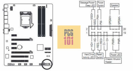
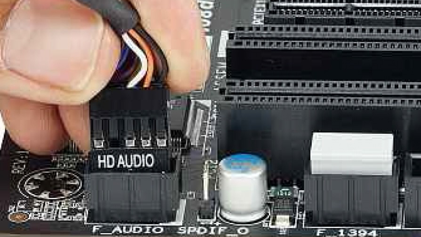
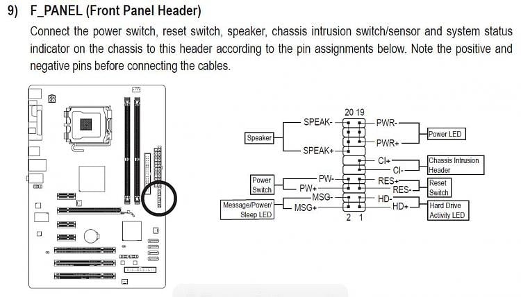
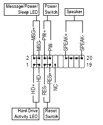
Motherboards that use this model front panel pinout are: Asus P5KPL/EPU, Asus P5Q-EM, Asus P5Q SE2. Front Panel 20 Pin | Some Call It 13 (or 20 – 7) Pin. It is similar to the 10 pin (10-1) diagram but this one has a speaker connector. Motherboards that use this model front panel pinout are: Motherboard front panel connection diagram. Which is the and which is the. These will be used for hard drives and cd dvd drives. I am installing a new motherboard in one of my computers. If you need help with any of these connection or anything else to do with. Once you remove the side panel you will see the control box.
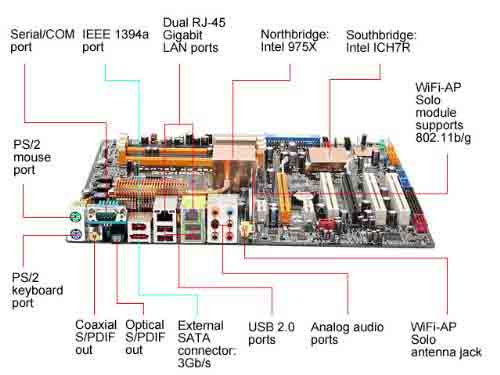
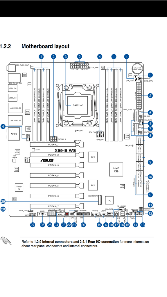
Let’s take a look at a typical higher level motherboard for an example of connector and port types. We chose the Asus Prime X470-Pro for its inclusion of many modern motherboard features, and its contrasting color design, which makes it easier to see smaller board components. Above we’ve illustrated many of the common motherboard port and connector types. Of course, not all boards feature all types, and things like fan headers, M.2 connectors, and the BIOS battery will be located in different spots on different boards. Also note that the M.2 connector (#6 in our diagram above) may have up to four PCIe 3.0 or 2.0 lanes feeding to it. Today’s fastest NVMe drives utilize four PCIe lanes for maximum speed, but some (like MyDigitalSSD’s SBX drives) use just two lanes to hit lower price points while still being much faster than SATA drives. Alternatively, an M.2 slot may only connect to SATA lanes/drives, or it may support both SATA and NVMe/PCIe drives. So be sure to check what the board...
Motherboard connection diagram
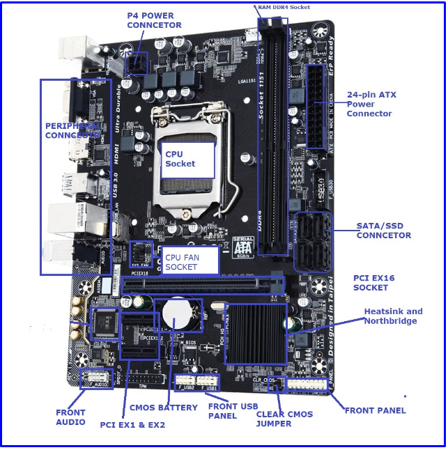
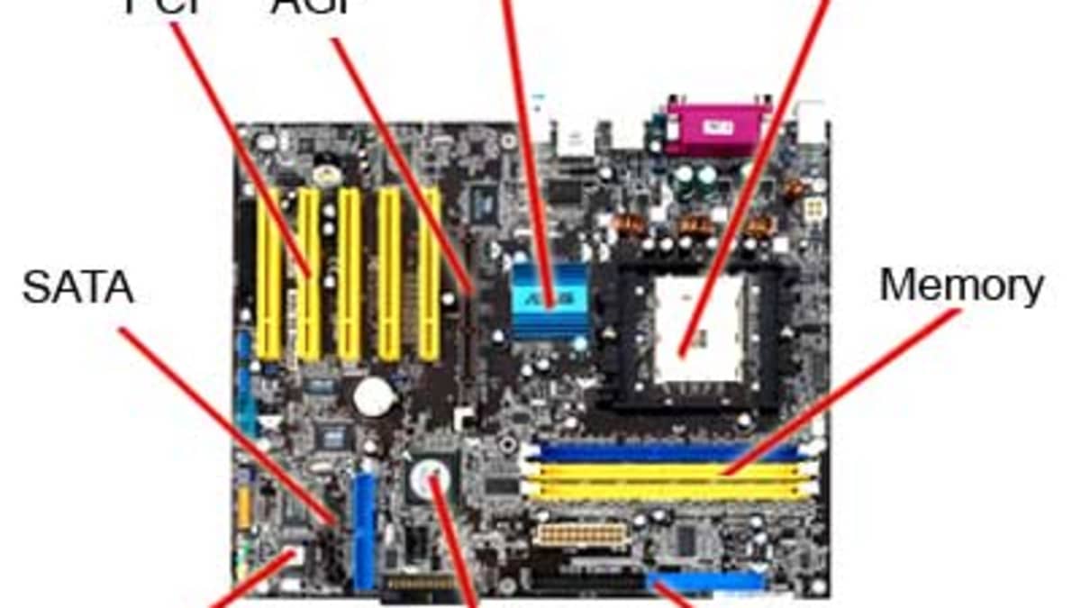
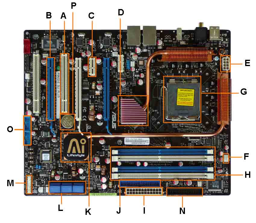
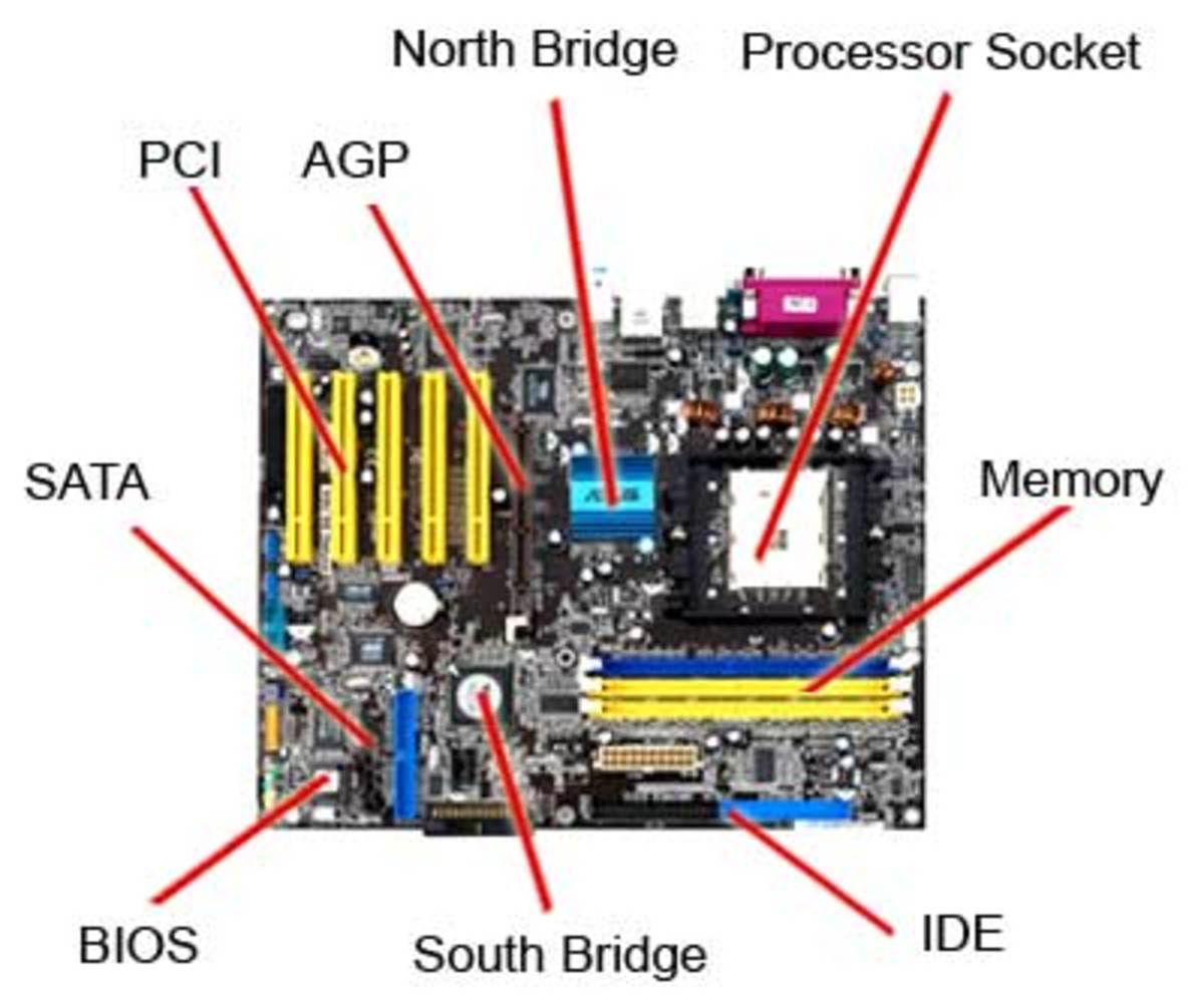
motherboard allow communication through cables with various peripheral devices, both inside and outside the compu ter case. ATX motherboard legend 1. Processor socket 2. Chipset 3. RAM slots 4. AGP graphic card slot 5. PCI slots 6. CNR modem slot 7. Audio chip 8. I/O chip 9. BIOS 10. ATX power connector 11. Floppy drive connector 12. ATA ... Motherboard connectors pinouts. A Motherboard (sometimes alternatively known as the mainboard, system board, planar board or logic board, or colloquially, a mobo) is the main printed circuit board (PCB) found in computers and other expandable systems. It holds and allows communication between many of the crucial electronic components. Diagram of Motherboard Components and Connectors. Below, we’ve put together a diagram of the most important parts of the motherboard. Motherboard layouts may vary between models (for instance, higher-end boards may have more heatsinks, memory slots, or M.2 slots), however all modern boards tend to have the same general layout, regardless of manufacturer or chipset.
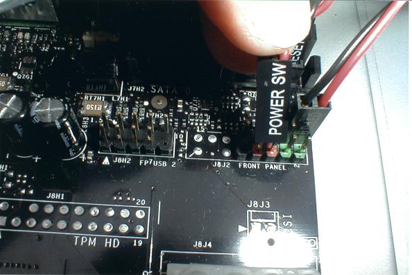
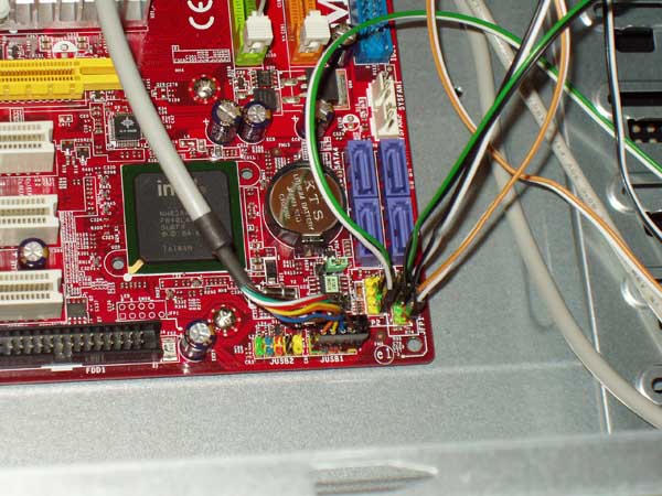
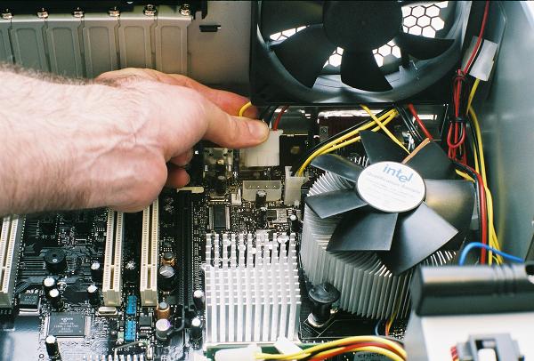
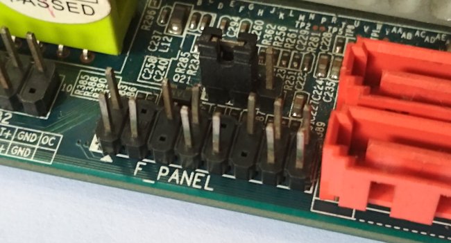
Motherboard connection diagram. The layout of the pins varies from motherboard to motherboard, although they are usually grouped together and color-coded. You may or may not use all of the connectors. Sometimes the power LED has a blank pin between the two wires. You can buy an adapter to change the pin layout or simply cut the connector to accommodate the pins. Motherboard Wiring Diagram– wiring diagram is a simplified enjoyable pictorial representation of an electrical circuit.It shows the components of the circuit as simplified shapes, and the gift and signal contacts between the devices. A wiring diagram usually gives opinion not quite the relative point and contract of devices and terminals on the devices, to encourage in building or servicing ... Connect the serial port module cable to this connector, then install the module to a slot opening at the back of the system chassis. 2. CPU and chassis fan connectors (4-pin CPU_FAN, 4-pin CHA_FAN) Connect the fan cable to the fan connector on the motherboard, ensuring that the black wire of the cable matches the ground pin of the connector Msi Motherboard Wiring Diagram. JPWR1 (24 pins) is the main ATX power connector, while JPWR2 (8 pins) is Note that some motherboards (though not the MSI Z97 PC Mate). Msi motherboard wiring diagram emachines motherboard wiring diagram motherboard power switch wiring pc motherboard wiring diagram. Msi Motherboard Wiring Diagram - Msi Pm8pm-v ...
24.08.2018 24.08.2018 3 Comments on Msi Motherboard Wiring Diagram. Is there a way I can have both front connectors and Motherboard Most front case connectors even include wires to return the signal back to. Unlike the Intel motherboards, the Front Panel Connector Header (JFP1) on the MSI H61M-P31 motherboard is not colour coded. ... Diagram of Motherboard Components and Connectors. Below, we’ve put together a diagram of the most important parts of the motherboard. Motherboard layouts may vary between models (for instance, higher-end boards may have more heatsinks, memory slots, or M.2 slots), however all modern boards tend to have the same general layout, regardless of manufacturer or chipset. Motherboard connectors pinouts. A Motherboard (sometimes alternatively known as the mainboard, system board, planar board or logic board, or colloquially, a mobo) is the main printed circuit board (PCB) found in computers and other expandable systems. It holds and allows communication between many of the crucial electronic components. motherboard allow communication through cables with various peripheral devices, both inside and outside the compu ter case. ATX motherboard legend 1. Processor socket 2. Chipset 3. RAM slots 4. AGP graphic card slot 5. PCI slots 6. CNR modem slot 7. Audio chip 8. I/O chip 9. BIOS 10. ATX power connector 11. Floppy drive connector 12. ATA ...
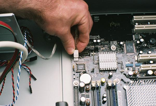
Build Your Own Pc Step 5 Making Motherboard Connections
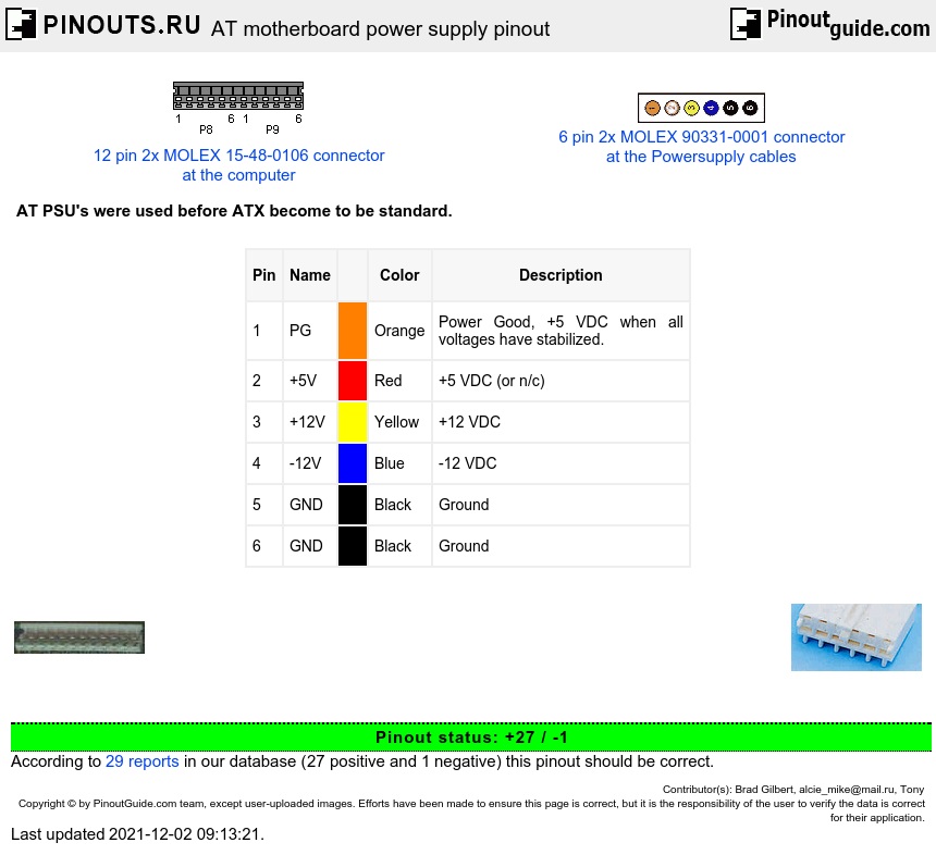
At Motherboard Power Supply Pinout Diagram Pinouts Ru

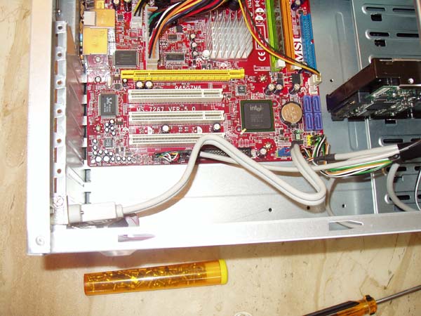
Solved Need Motherboard Connection Diagram For Msi 7318 Fixya

Motherboard Printed Circuit Board Download Scientific Diagram

Motherboard Layout Diagram Quizlet
What Is A Motherboard Definition Diagram

Testing The Charging Circuit On A Laptop Motherboard Part 1 Laptop Motherboard Computer Maintenance Motherboard
Computer Wiring How To Connect Your Computer Wires
Build Your Own Pc Step 5 Making Motherboard Connections
Motherboard Layout
How To Connect Power Button To Motherboard Pc Guide 101
Wiring Diagram Schematic Circuit Diagram Motherboard Png 1000x565px Wiring Diagram Area Asus Brand Cable Harness Download
Computer Wiring How To Connect Your Computer Wires
How Where To Properly Install Pc Cables Wires For Ssd Panel Switches And More

Geiop Gif 2234 1656 Electrical Wiring Diagram Circuit Diagram Electrical Diagram
2
What Is The Motherboard In Computer Components And Definition Of Motherboard With Diagram Concepts All
Motherboard Parts Functions

Motherboard Components Diagram Quizlet

Motherboard Schematic Circuit Diagram And Bios Gigabyte Ga B75m D3p 4mb75md3p 00 20a Rev 2 0a Boardview Schematic Circuit Diagram
Motherboard Front Panel Connection Diagram Wiring Site Resource
10 Parts Of A Motherboard And Their Function Turbofuture

Anatomy Of A Motherboard Vrm Chipset Pci E Explained Gamersnexus Gaming Pc Builds Hardware Benchmarks
Computer Wiring How To Connect Your Computer Wires

Wiring Diagram Connections For P7 1010 Motherboard Hp Support Community 4878319
Build Your Own Pc Step 5 Making Motherboard Connections
Motherboard Power Connectors Cpus Motherboards And Memory Linus Tech Tips
How Where To Properly Install Pc Cables Wires For Ssd Panel Switches And More

Laptop Motherboard Schematic Diagram Schema Wiring Diagram Circuit Diagram Circuit Diagram Data Architecture Diagram
Motherboard Diagram Identify Components For Motherboard Upgrades Or Replacement

Motherboard Wikipedia
Mainboard Front Panel Connector Diagrams Graphics Learning
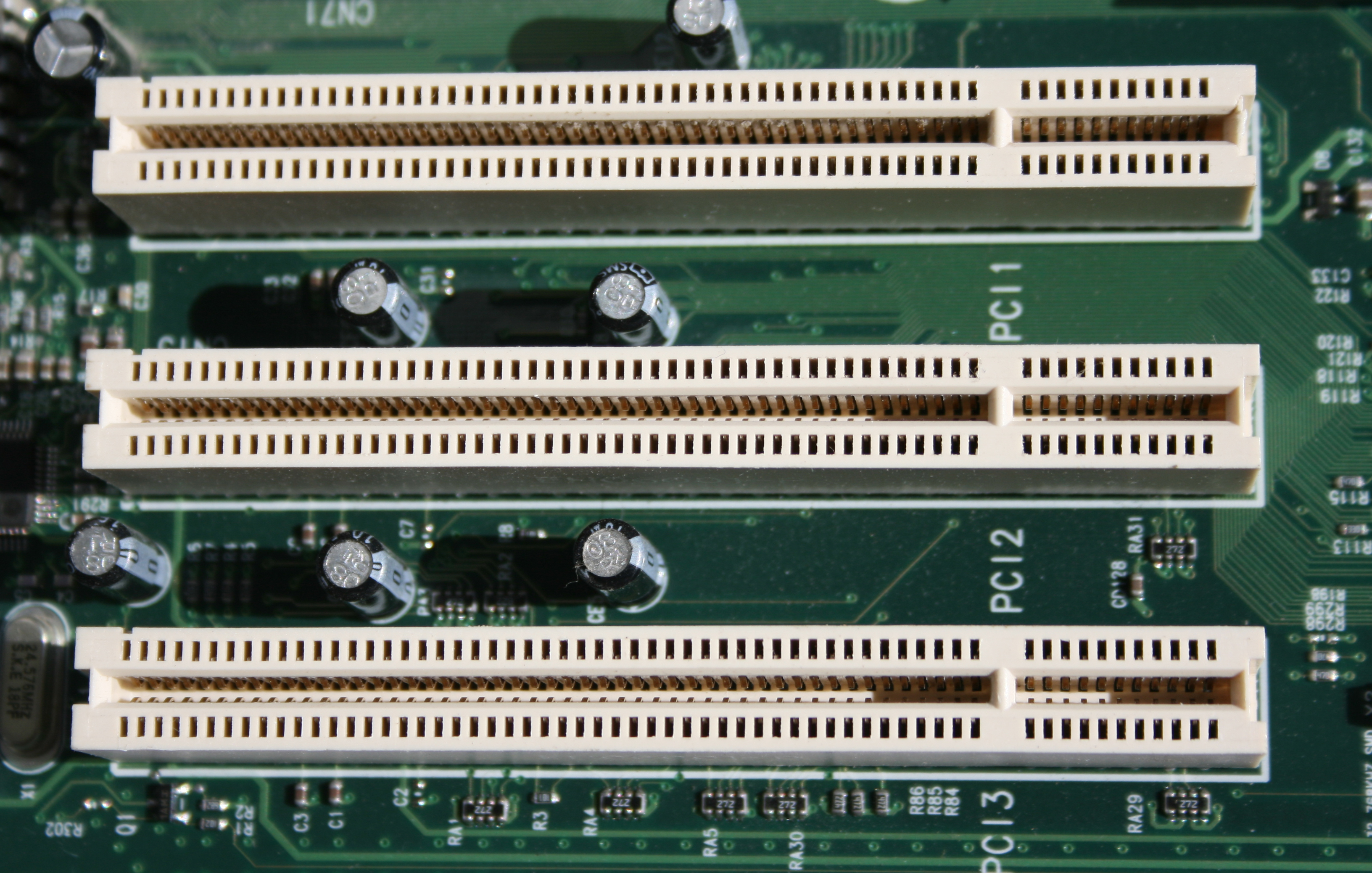
Peripheral Component Interconnect Wikipedia

Motherboard Diagram Wiring Chart And Connection Guide Basics Bright Hub
10 Parts Of A Motherboard And Their Function Turbofuture

Motherboard Diagram With Labeled Questions Answers With Pictures Fixya
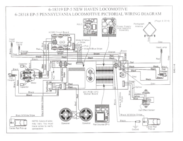
Lionel Motherboard Wiring Diagrams O Gauge Railroading On Line Forum

Laptop Notebook Motherboard Circuit Diagra Laptop Notebook Motherboard Circuit Diagram Laptop Repair Circuit Diagram Computer Repair Services


Comments
Post a Comment