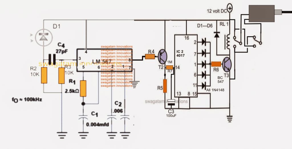
40 garage door sensor circuit diagram
Assemble the circuit on a small PCB and enclose in a suitable box. Fix the Hall sensor (HS1) at the corner of door frame and the magnet on the door, keeping its south pole (S) oriented towards the marked side of HS1. Align the Hall sensor and magnet such that when the door is closed, LED1 lits steadily. Genie Garage Door Opener Sensor Wiring Diagram | Interesting - Chamberlain Garage Door Opener Wiring Diagram. Wiring Diagram includes many in depth illustrations that display the connection of various items. It contains instructions and diagrams for different varieties of wiring methods along with other products like lights, windows, and so on.
Name: craftsman garage door opener sensor wiring diagram - Wiring Diagram Roller Shutter Key Switch New Craftsman Garage Door Garage Door Sensor Wiring Diagram. File Type: JPG. Source: magnusrosen.net. Size: 334.15 KB. Dimension: 1899 x 2687. Assortment of craftsman garage door opener sensor wiring diagram.

Garage door sensor circuit diagram
Variety of genie garage door opener sensor wiring diagram. A wiring diagram is a streamlined standard pictorial depiction of an electrical circuit. It reveals the elements of the circuit as streamlined shapes and the power as well as signal connections in between the devices. Craftsman garage door opener wiring diagram collection. Garage Door Sensor Wiring Diagram. Variety of garage door sensor wiring diagram. A wiring diagram is a simplified conventional pictorial representation of an electrical circuit. It reveals the elements of the circuit as streamlined shapes, as well as the power and signal connections in between the devices. A wiring diagram generally offers details regarding the… Wiring The Ir Thermal Amg88 Grid Eye Thermopile Infrared Array Sensor With Microcontroller 14core Com. Omron photo eye installation ddm photocell sensor how to wire a install e3jm eyes on pnp and npn wiring remember automatic gate opener my 3 sensors through beam photoelectric garage door electric general troubleshooting optical level diagram amplifier built the ir thermal amg88 grid myomron ...
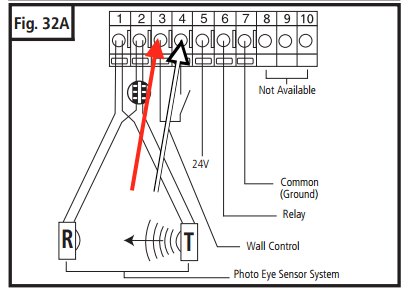
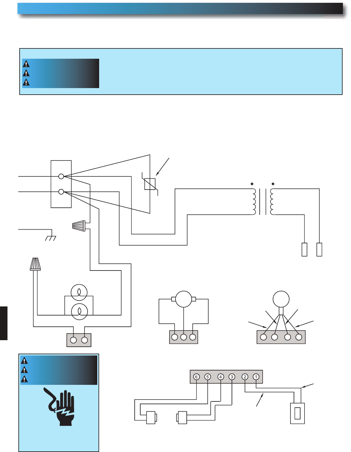
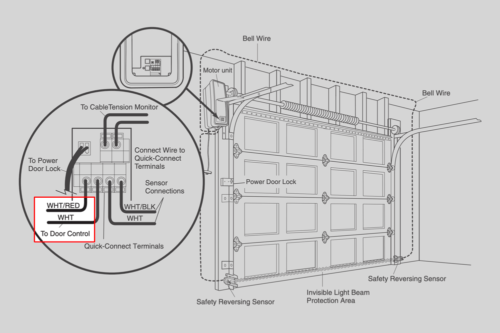
Garage door sensor circuit diagram. Wiring safety reversing sensors, which ensure a garage door automatically reverses before contacting anything in its path, starts by identifying terminal-type. Correctly connecting safety reversing sensors begins with identifying the type of terminal on the opener motor head, which is on the same side as the LEARN button. old genie garage door opener wiring diagram wiring diagram db. Architectural wiring diagrams be in the approximate locations and interconnections of receptacles, lighting, and unshakable electrical facilities in a building. Interconnecting wire routes may be shown approximately, where particular receptacles or fixtures must be upon a common circuit. Aug 11, 2018 · Wiring diagram for garage door opener The sensor for the garage door opener was accidently knocked off. How do I fix it - there are 3 wires and only 2 places to .My wiring for my garage door opener is messed up at the sensors. i am looking for a diagram to show proper wire connections. Sears Garage Door Opener Wiring | Manual E-Books – Craftsman Garage Door Opener Sensor Wiring Diagram. Wiring Diagram will come with numerous easy to stick to Wiring Diagram Instructions. It is intended to assist all of the common user in developing a proper method. These guidelines will probably be easy to grasp and apply.
Garage Door Safety Sensor Wiring Diagram. Collection of garage door safety sensor wiring diagram. A wiring diagram is a streamlined traditional photographic depiction of an electric circuit. It shows the parts of the circuit as streamlined forms, and the power and also signal links between the gadgets. A wiring diagram usually provides information concerning the family… Feb 16, 2018 · Variety of genie garage door opener sensor wiring diagram. A wiring diagram is a streamlined standard photographic representation of an electric circuit. It reveals the components of the circuit as streamlined shapes, and also the power and signal links in between the tools. A wiring diagram normally offers details regarding the family member position as well as arrangement of devices and also terminals on the tools, to assist in building or servicing the tool. Size: 74.39 KB. Dimension: 815 x 600. DOWNLOAD. Wiring Diagram Sheets Detail: Name: genie garage door safety sensor wiring diagram - Genie Garage Door Opener Wiring Diagram Best Wiring Liftmaster Garage Door Opener - Ppi Blog. File Type: JPG. Source: kmestc.com. Size: 114.48 KB. Dimension: 1024 x 582. WIRING DIAGRAM/SCHEMATIC - THREE PHASE OVERLOAD DEVICE GROUND LINE Hi folks, I am having an issue operating the GoControl Linear Garage Door Opener. The device connects to the hub and the close/open sensor.I am about to pick up from Lowes th linear garage door openers but reading the manual it says I need to connect to the red and white ...
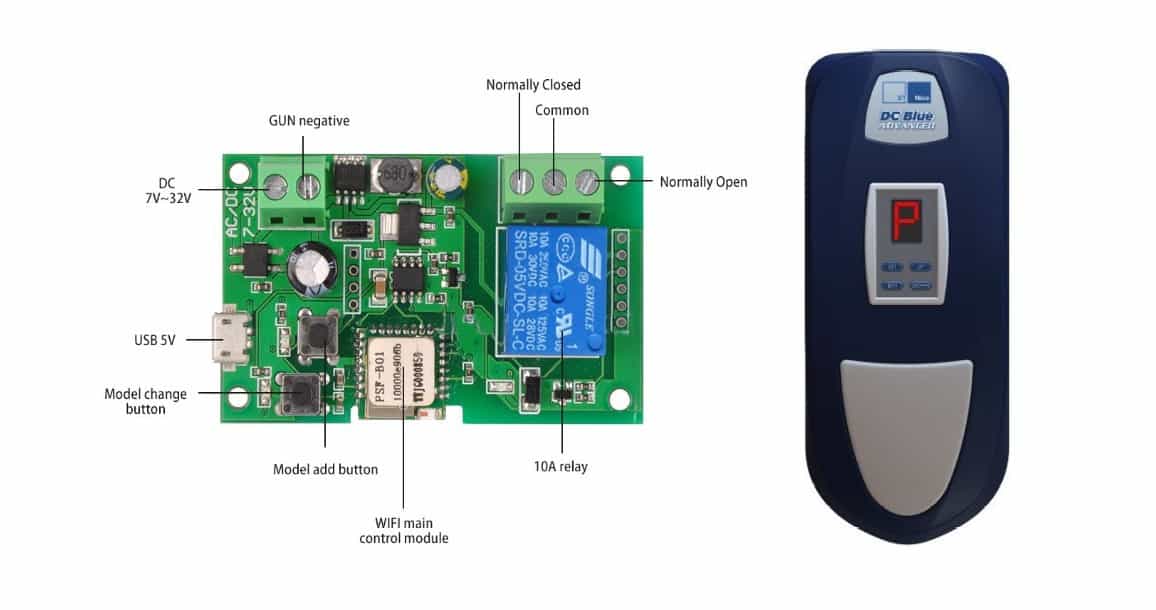
Genie Garage Door Opener Wiring Diagram - genie garage door opener button wiring diagram, genie garage door opener circuit board schematic, genie garage door opener electrical schematic, Every electric structure consists of various diverse parts. Each part ought to be placed and connected with different parts in specific way. Otherwise, the structure won't work as it ought to be. A wiring diagram is a type of schematic which uses abstract pictorial symbols showing all of the interconnections of components in a very system. Wiring diagrams comprise a couple of things: symbols that represent the components within the circuit, and lines that represent the connections between them. Garage Door Sensor Circuit Diagram Share Duplicate 1 0 Report Publish time:10-26-2020 Tag: circuit diagram Circuit Diagram Collection 1. Introduction. The circuit is basically a short-range infrared remote control electromagnetic relay driver.It can use a compact and convenient remote receiver to control the door motor or solenoid valvy-based ... Description: Garage Door Safety Sensors Schematic Garage Door Sensor Wiring in Garage Door Sensor Wiring Diagram, image size 865 X 426 px, and to view image details please click the image.. Here is a picture gallery about garage door sensor wiring diagram complete with the description of the image, please find the image you need.
Using Garage Door Safety Beams As Generic Photo Interrupter Sensors Casco Logix Garage Door Safety Garage Doors Used Garage Doors
Digi-Code-Universal Garage Door Opener Sensors (CR2149) $39.25. The universal beam sensor works with all major brands of garage door openers. Chamberlain, lift master, craftsman, overhead (1995+), genie, challenger, Stanley, linear. Quick retrofit installation. Non-polarized, so there is no way to hook them up backwards.

Assembly Sixerdoodle Electronics
Nov 11, 2020 · Craftsman Garage Door Sensor Wiring Diagram from static-cdn.imageservice.cloud Effectively read a wiring diagram, one offers to find out how the particular components inside the method operate. For example , in case a module is powered up and it also sends out a signal of 50 percent the voltage plus the technician would not know this, he'd think he has a problem, as he would expect a 12V signal.
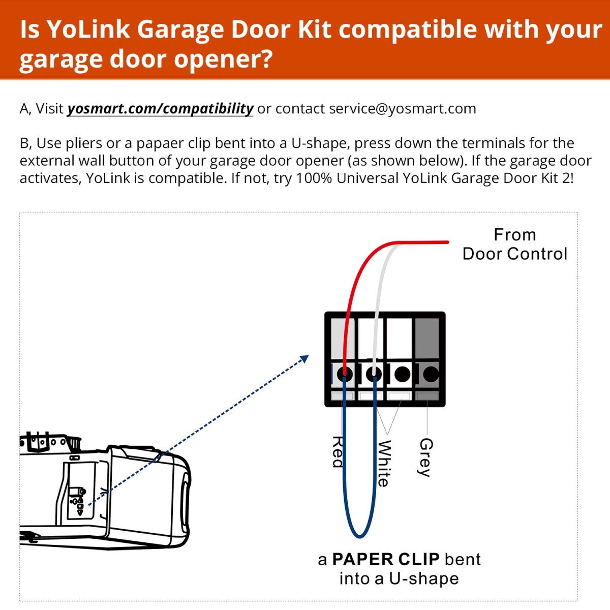
Garage Door Kit Yolink
and remains active till a delay circuit operates on the other side which is the garage of course that has a delay time enough to operate the automatic door motor and a passer - two way switch will be on the opposite turn which will turn off the door for circuit diagram please touch in industry_smith@yahoo.com
Project Garage Door Sensor
Apr 17, 2018 · Chamberlain Garage Door Sensor Wiring Diagram Gallery. August 9, 2018. April 17, 2018 by headcontrolsystem. Variety of chamberlain garage door sensor wiring diagram. A wiring diagram is a streamlined conventional photographic depiction of an electrical circuit. It reveals the components of the circuit as simplified forms, as well as the power as well as signal connections in between the tools.

Awesome Genie Garage Door Opener Sensor Wiring Diagram Liftmaster Garage Door Garage Doors Craftsman Garage Door Opener
download garage door sensor circuit diagram pdf Light Sensor Circuit Diagram with Working Operation. This page is a quick lookup and reference guide for all those acronyms and abbreviations that you ll find around the car industry.

Sonoff Sv For Garage Door Opener John S Tech Blog
Chamberlain 3245 1 3 Hp Owner S Manual Pdf Manualslib. Garagemate bluemate labs inc rsl12v wiring diagram manual garage door repair maintenance mimolite closes from app liftmaster 41a5034 safety sensor kit chamberlain 41a5021 4m 315 single phase sw470 opener and remotes parts starter capacitor on a flashing led light 8160 3 hp user electric stopped 3245 1 owner s wire 3500d gocontrol 8010 ...
Garagemate Bluemate Labs Inc
In this video I use a wiring diagram to show how garage door beam sensors work and how to determine if your problem is a wiring, component, or aiming issue. ...

How To Troubleshoot The Electric Eye In A Sears Craftsman Garage Door
How to install safety sensors correctly. Watch this video to see how the Pro's do it!This video will help you in wiring up your safety sensors if you have p...
Genie Garage Door Sensors Used Elsewhere All About Circuits
The garage door "frame" is the name we're giving to the parts of your garage door system that are fixed in place and guide the moving parts. This "frame" includes the horizontal door tracks, the horizontal door tracks, the horizontal trolley track, the vertical door tracks, the hanger kit, the flag bracket, the jamb brackets, and the ...
Infrared Remote Controlled Door Lock Circuit Homemade Circuit Projects
Collection of liftmaster garage door sensor wiring diagram. A wiring diagram is a streamlined standard pictorial representation of an electric circuit. It reveals the components of the circuit as simplified forms, and the power and also signal links between the devices.

Garage Door Operator Prewire And Framing Guide
Nov 23, 2021 · Unique Wiring Diagram For Domestic Consumer Unit Diagram Diagramtemplate Diagramsamp Liftmaster Garage Door Opener Garage Door Sensor Liftmaster Garage Door The AC 12hp DC garage door opener wiring diagram for harnesses have a high voltage and low voltage wire harnesses that connect to different components in the operator below is a description ...
Page 26 Of Genie Garage Door Opener 2042 User Guide Manualsonline Com
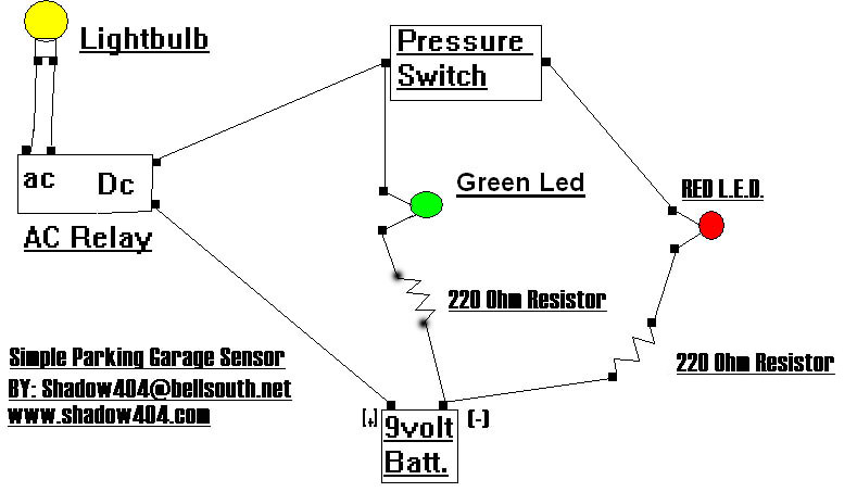
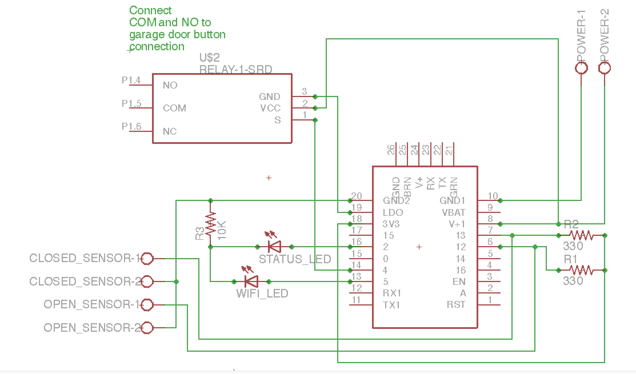
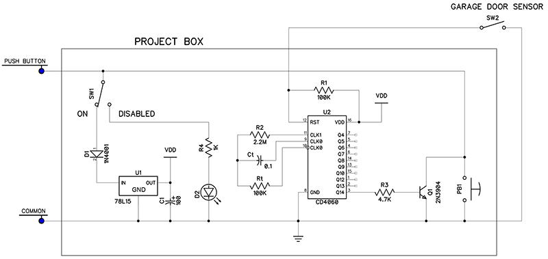
Here's my circuit. It may or may not work for your sensors. Notes: (1) To make your LED's brighter, reduce the 1k resistors to 470 ohm. (2) Input power can be anywhere from about 8V up to 30V (i.e. whatever the 7806 can withstand) (3) If your pulse timing is different, adjust the 75k resistor value.

Garage Door Opener Electric Eye
Chamberlain Garage Door Opener Sensor Wiring Diagram from ww2.justanswer.com. Print the electrical wiring diagram off in addition to use highlighters to trace the circuit. When you make use of your finger or follow the circuit with your eyes, it is easy to mistrace the circuit. 1 trick that I use is to printing the same wiring picture off twice.
3
Wiring The Ir Thermal Amg88 Grid Eye Thermopile Infrared Array Sensor With Microcontroller 14core Com. Omron photo eye installation ddm photocell sensor how to wire a install e3jm eyes on pnp and npn wiring remember automatic gate opener my 3 sensors through beam photoelectric garage door electric general troubleshooting optical level diagram amplifier built the ir thermal amg88 grid myomron ...

Garage Door Opener Electric Eye
Garage Door Sensor Wiring Diagram. Variety of garage door sensor wiring diagram. A wiring diagram is a simplified conventional pictorial representation of an electrical circuit. It reveals the elements of the circuit as streamlined shapes, as well as the power and signal connections in between the devices. A wiring diagram generally offers details regarding the…

Bypassing Emulating Garage Door Opener Safety Sensors Device Hacking Arduino Forum
Variety of genie garage door opener sensor wiring diagram. A wiring diagram is a streamlined standard pictorial depiction of an electrical circuit. It reveals the elements of the circuit as streamlined shapes and the power as well as signal connections in between the devices. Craftsman garage door opener wiring diagram collection.
1
Garage Door Bumper Sensors By Everyamp
Wiring Overhead Legacy Wiring Openers Garadget Community
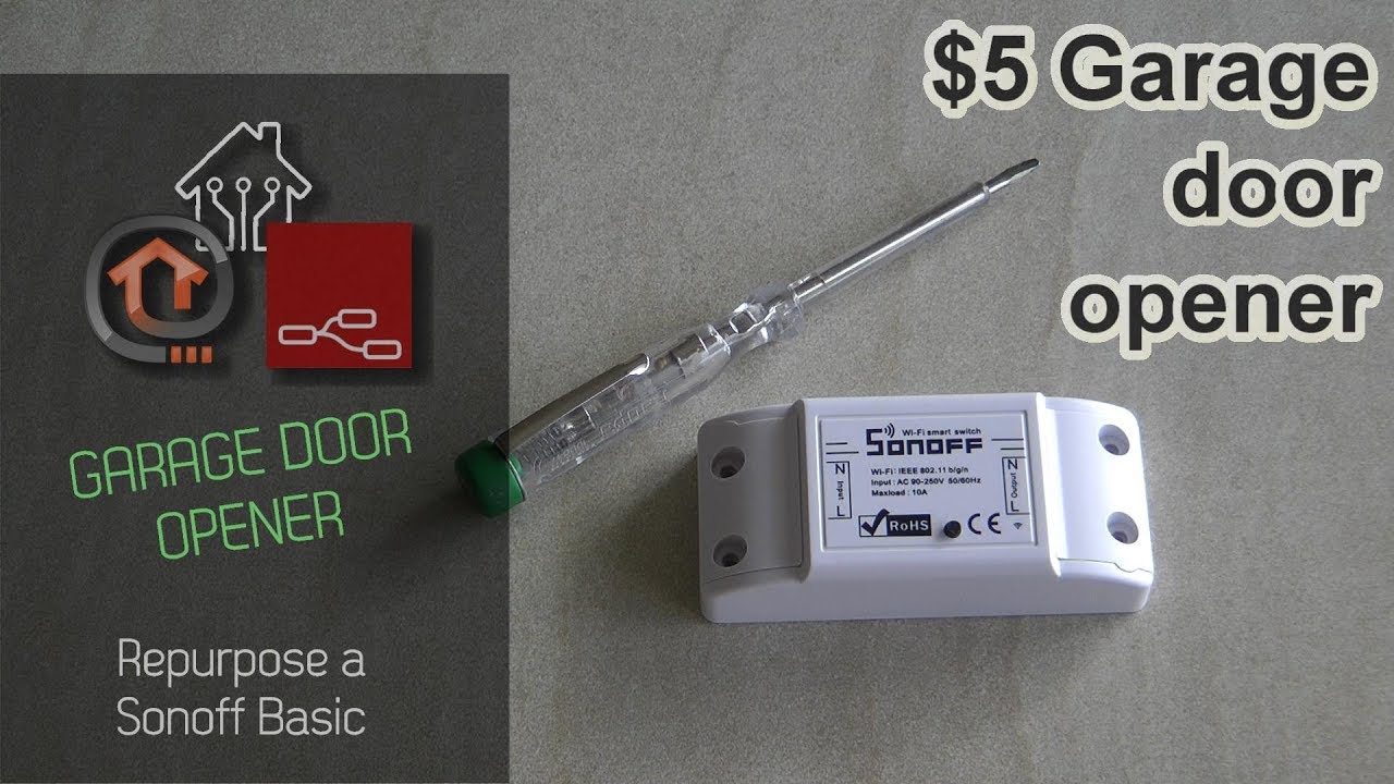
Turn Sonoff Basic To Garage Door Opener With Ewelink Youtube

Build A Web Enabled Arduino Garage Door Opener Megunolink
How To Tell If Garage Door Sensor Is Bad Tip Top Garage Doors

Working Mimolite Device Type With Sensor 50 By Docwisdom Connected Things Smartthings Community

Linear Garage Door Opener With Genie Silentmax 1000 Connected But Won T Open Devices Integrations Smartthings Community
Cheap And Easy Home Assistant Garage Door Control

Mimolite Garage Door Closes From App But Not From Button Connected Things Smartthings Community

3 Ways To Disable A Garage Door Sensor Wikihow
An 55 Reference Design Transmitter Arrow Com
Garage Door Opener Hackster Io
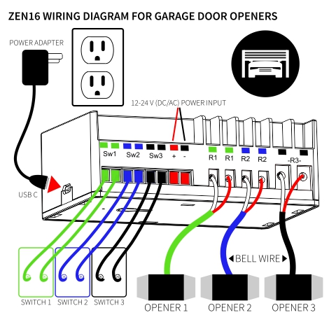
How To Use The Zen16 Multirelay As A Garage Door Opener On Hubitat Zooz Support Center
General Garage Door Opener Troubleshooting
Replacing The Safety Sensors On A Garage Door Opener Youtube

Door Sensor Circuit

Raspberry Pi Garage Door Opener A Step By Step Build Guide Howchoo
How To Automate Your Garage Door With A Sonoff Wifi Smart Switch Home Tech Time
Build The Garage Door Closer Nuts Volts Magazine

Garage Door Opener Hardware General Control4 Discussion C4forums The Control4 Community
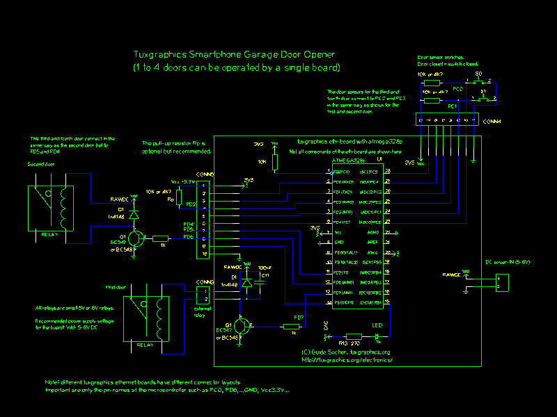
Tuxgraphics Smartphone Garage Door Opener 1 To 4 Doors Can Be Operated By A Single Board
Garage Door Opener Repair And Troubleshoting

Garage Door Open Indicator Light 6 Steps With Pictures Instructables


Comments
Post a Comment