41 5 wire regulator rectifier wiring diagram
All about motorcycleJHAY'D MECHANIC Regulator rectifier diagram here you are at our site this is images about regulator rectifier diagram posted by maria nieto in wiring category on may 08 2019. Provided below is an online pdf document for lamberts bikes 3 phase 6 wire regulator rectifier wiring diagram.
Auto parts accessories 4 wire full motorcycle regulator rectifier tester voltage wiring harley a for mosfet kawasaki 6 universal 12 volt units atv gy6 50 150cc scooter wires 5 2 phase pma install too high 3 and rectifiers wave black motored pins flwd suzuki 32800 30b01 12v lucas regulators diagram pin with. 6 volt solid state regulator rectifier.

5 wire regulator rectifier wiring diagram
Wiring diagram for voltage regulator. Fluctuation in voltage can harm these electrical mechanisms. This is a image galleries about 5 wire rectifier wiring. If you want the image to be deleted please contact us we will delete it from our website. Chinese voltage regulator wired up to honda gx clone with charge coils. 2 phase 5 wire motorcycle regulator rectifier wiring diagram pdf. We ve even included standard wire colours where appropriate. Lamberts bikes motorcycle part wiring diagrams. Simply plug the connector onto the 5 pins row and make sure that the pin assignments and wire assignments are matched correctly. M 3 2 2 2 phase 5 wire. 5 pin regulator rectifiier wiring diagramSana makatulong po ito sainyo mga bro.Para sa iba pang vidio wag nyo pong kalimutan magSUBSCRIBELIKE AND SHARETO GOD...
5 wire regulator rectifier wiring diagram. Universal Parts 12 Volt 6 Amp YTX7A-BS Battery - Maintenance Free Dry AGM 12, , 5 pin Regulator for cc and cc GY6 engines commonly found Universal Parts Complete Wiring Harness for cc and cc 4-stroke GY6. rectifier/regulator go along with the other items running on the electrical system; stator common on most 50cc scooter but also can be found ... This wiring works on every bike I know of so far. Just leave the old regulator connector that went to the battery unplugged and taped so it can't short out to your frame or some other grounded spot. The other 3 wire connector on the old regulator is the stator wires. These wires will come from the engine case. May 11, 2018 - Wiring Diagram: 5 Pin Rectifier Wiring Diagram. Jeff Sessions 2nd ... regulator/rectifier. The rectifier actually converts the power from AC to DC, while the regulator keeps the power level (voltage) from going above the 13.8 -14.5 volts needed to power a standard 12 volt battery. It is important that the stator provides more power than needed by the motorcycle so that the battery will stay charged.
5 Wire Stator Wiring Diagram. 5 Wire Stator Wiring Diagram - wiring diagram is a simplified good enough pictorial representation of an electrical circuit. It shows the components of the circuit as simplified shapes, and the talent and signal contacts amongst the devices. A wiring diagram usually gives recommendation virtually the relative ... Replacing The $100 Voltage Regulator On Outboard Motors With A $4 - Mercury Outboard Rectifier Wiring Diagram. The diagram offers visual representation of the electrical structure. However, this diagram is a simplified version of this arrangement. This makes the procedure for assembling circuit simpler. This diagram provides advice of circuit ... 5 Wire Regulator Rectifier Wiring Diagram - wiring diagram is a simplified tolerable pictorial representation of an electrical circuit. It shows the components of the circuit as simplified shapes, and the capability and signal connections along with the devices. Aftermarket Honda Regulator Rectifier. After pulling out the the stock regulator and rectifier it seems like it will add up. On the stock regulator there is a green/ solid black/ black and red wire and the rectifier has a red/3 wight/ and a black. So do you think the. -3 yellow from the new unit replace the three wight from the old. -new green replace old green.
5 Pin Rectifier Wiring Diagram - wiring diagram is a simplified agreeable pictorial representation of an electrical circuit. It shows the components of the circuit as simplified shapes, and the faculty and signal contacts amongst the devices. A wiring diagram usually gives instruction nearly the relative approach and treaty of devices and ... 17.02.2019 17.02.2019 7 Comments on Briggs And Stratton Voltage Regulator Wiring Diagram shunt is designed to read voltage drops due to the resistance of the metal be- tween the Two wires of the same color feeding a regulator/rectifier is a rectified . Rectifier Regulator Wiring Diagram - 12v rectifier regulator wiring diagram, atv regulator rectifier wiring diagram, honda regulator rectifier wiring diagram, Every electric structure consists of various distinct components. Each part should be placed and linked to different parts in particular way. Otherwise, the arrangement will not work as it ought to be. Regulator For Honda Xrm 110 Motorcycle 4 Pin Ac Wiring Diagram Lazada Ph. Regulator Rectifier 4 Pin Flat Storm Parts For Chinese Bikes. Half Wave 12v Rectifier Regulator Solution For Puch And Others Moped Army. 4 Pin No Wire Regulator Rectifier For Gy6 Scooter Bike Atv Dirtbike Snapitup Co Za. 2 3 And 4 Wire Rectifiers.
Lambretta 5 Pin Regulator Wiring Diagram
Normally, the pins for USB1 and USB2 are in seperate rows. Diagram 2: Simply plug the connector onto the 5-pins row, and make sure that the pin assignments and wire assignments are matched correctly. Diagram 3: Alternatively, you can plug the connector onto the 4-pins row, and leave the S-GND wire unconnected.

Wiring Diagram For Tympanium Voltage Regulator-rectifier ...
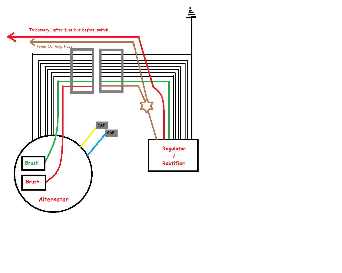
Regulator/Rectifier Replacement by BassCliff ... The red wire gets connected to the hot wire in the bike's wiring harness that leads through the fuse box and eventually to the positive battery terminal. On 6 wire units, that wire is a "sense" wire which gets ... Note that on the 5 wire units, there is no "sense" wire to connect. The unit

6 Pin Regulator Wiring Diagram - 6 pin voltage regulator ...
Motorcycle 5 Wire Regulator Rectifier Wiring Diagram. Diagram 12 24 rectifier wiring 4 wires voltage regulator motorcycle tester atv gy6 50 150cc scooter moped jcl nst 5 pin a plug mujun 6 volt. 4 Wires Voltage Regulator Rectifier Electrical For Motorcycle And Boat Motors Diy Engines Online In Vietnam B07l94ntsb.

BATTERY SOLUTIONS: December 2012
5 Wire Regulator Rectifier Wiring Diagram from ae01.alicdn.com. To properly read a cabling diagram, one provides to know how the components inside the method operate. For instance , if a module is powered up and it also sends out the signal of fifty percent the voltage and the technician would not know this, he would think he offers a challenge ...

BDX 8 And 11 Pole Stator Installation Guide :: BuggyDepot ...
rectifier/regulator go along with the other items running on the electrical system; Here is a wiring diagram of the typical 5-wire CDI system on a lot of scooters comprising pick-up input, battery +12 volts in, Gnd, and Ignition coil out pins.some common electrical setups and included the wiring diagrams.

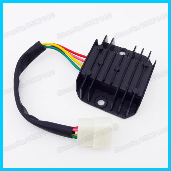
Universal 12V 5 Pin Wire Voltage Regulator Rectifier For ...
Measurements sun 4 inches L X 1 12 inches W sand 5 inches L X 1 12 inches W ocean 6 inches L X 1 12 inches W. 5 Pin Rectifier Regulator Wiring Diagram. Ford 6 Volt Positive Ground Wiring Diagram Gmc Truck Radio Wire inside 6 Volt Positive Ground Wiring Diagram image size 3804 X 1968 px and to view image details please click the image.

6 Wire Rectifier Wiring Diagram - Wiring Diagram Networks
Below are several of the top illustrations we get from different resources, we hope these pictures will certainly serve to you, and also hopefully very pertinent to exactly what you desire about the 3 Wire Rectifier Regulator Wiring Diagram is. Marvellous Motorcycle Regulator Rectifier Wiring Diagram Ideas, size: 800 x 600 px, source: farhek.com.
View Wiring Diagram Xrm 125 Pics
panel where the rectifier are open, causing high "ripple" or A/C voltage (while charging volts and amps are still. I replaced the voltage regulator (aftermarket, not Polaris), and I thou Polaris had a 3-wire regulator-rectifier that was used on sleds with electric start. Studying the wiring diagram a bit more, I can see that elec start sleds.

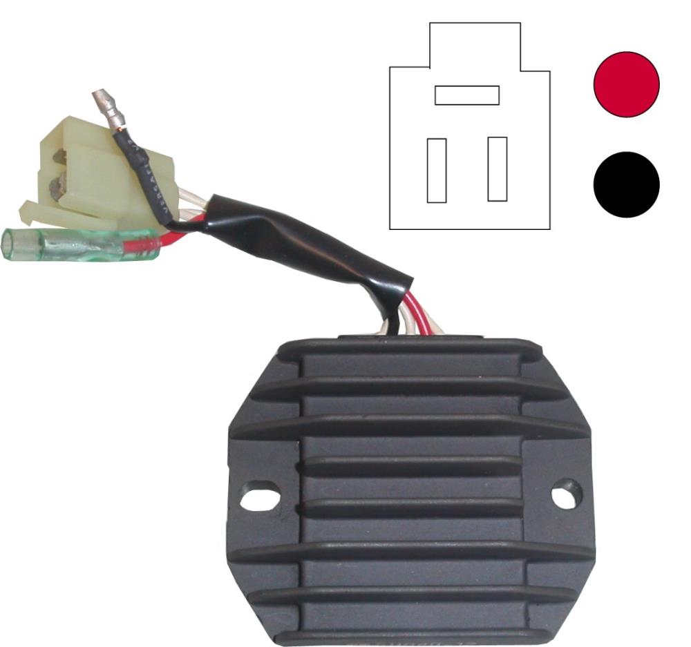
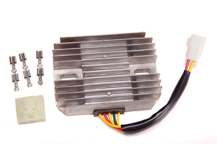
5-wire Regulator Rectifier Male Connector For Honda CBR600 ...
Recitifer Regulator Signal Wires. Many Rick's Motorsport Electrics Rectifier/Regulators eliminate what is commonly referred to as a "signal wire" on OE pieces. For example, on a 1981 Kawasaki KZ440, there are 5 wires going to the OE part: 2 yellow wires (AC inputs), white/red (DC "+" output), black/yellow (DC "-" output), and a ...
Battery Charging Problems - ATVConnection.com ATV ...
Your regulator has to match the stator you have. You either have the wrong regulator or a bad one. If you don't have a 5 wire hook-up, try going with a 4 pin reg. Put the Yellow and white diagonal from each other and the green and red diagonal from each other on the other 2 pins. Dave @ Absolutely Scooters.

Re: Is there a cheep and reliable regulator rectifier ...
Understanding motorcycle voltage regulator wiring homemade circuit projects building a rectifier for electronics forums chin atv gy6 50 150cc scooter 4 wires boat sho singapore tester new to indiana 650 6 stock can i use 5 wire ducati ms the ultimate forum 3 phase circuits upgrade honda yamaha rectifiers page recitifer signal rick s motorsport electrics blog and… Read More »

5 Wire Regulator Rectifier Wiring Diagram - easywiring
5 pin regulator rectifiier wiring diagramSana makatulong po ito sainyo mga bro.Para sa iba pang vidio wag nyo pong kalimutan magSUBSCRIBELIKE AND SHARETO GOD...

6 Wire Rectifier Wiring Diagram - Wiring Diagram Networks
2 phase 5 wire motorcycle regulator rectifier wiring diagram pdf. We ve even included standard wire colours where appropriate. Lamberts bikes motorcycle part wiring diagrams. Simply plug the connector onto the 5 pins row and make sure that the pin assignments and wire assignments are matched correctly. M 3 2 2 2 phase 5 wire.

Kawasaki 6 Wire Regulator Rectifier Wiring Diagram : 150cc ...
Wiring diagram for voltage regulator. Fluctuation in voltage can harm these electrical mechanisms. This is a image galleries about 5 wire rectifier wiring. If you want the image to be deleted please contact us we will delete it from our website. Chinese voltage regulator wired up to honda gx clone with charge coils.

6 Wire Rectifier Wiring Diagram - Wiring Diagram Networks
Honda Regulator Rectifier Wiring Diagram Database - Wiring ...

Aliexpress.com : Buy GY6 50 150cc Scooter Voltage ...

Gy6 Rectifier Wiring Diagram - MORPHINE-AND-DRUGS

Moped electrical problem | BeamNG

5 Wire Regulator Rectifier Wiring Diagram

1976 XS650 Bobber Wiring w/ Pamco Ignition???? | Welcome ...

Regulator Booster | Welcome to the XS-650 Garage USA
Yamaha Rectifier Wiring - Wiring Diagram Schemas

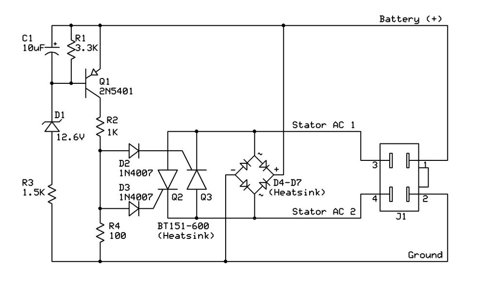
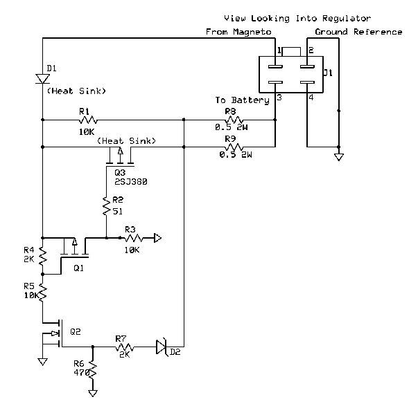
Figure 5-2. Typical Rectifier Wiring Diagram

5 Wire Regulator Rectifier Wiring Diagram
Motorcycle Parts Suzuki GSXR 750 W 1998 New 5 Wire 5 Pin ...

Voltage Regulator / rectifier units
Regulator / Rectifier 5 Wire - REGR026 | CMPO | Chinese ...
110cc Atv Rectifier Wiring Diagram

4-Wire Full Wave Motorcycle Regulator Rectifier 12V DC ...
4 Pin Regulator Rectifier Wiring Diagram - Diagram For You

6-Wire / 2-Plug Voltage Regulator Rectifier - Version 35

5 Wire Regulator Rectifier Wiring Diagram - Schematic ...

Gy6 5 Wire Rectifier Wiring Diagram - WIRGRAM

6 Wire Regulator Rectifier Wiring Diagram : 6v OR 12v ...

Honda Motorcycle 2017 OEM Parts Diagram for Wire Harness ...
Yamaha Rectifier Wiring - Wiring Diagram Schemas

Chinese ATV Voltage Regulator Rectifier 6-Wire 2-Plug ...

zapłon cdi w awo turist | Forum Jednoślad.pl

For Sale - - Harness | Yamaha XS650 Forum

Voltage Regulator Rectifier for Mercury Mariner Outboard ...


Comments
Post a Comment