42 arbitrary waveform generator block diagram
System Block Diagram. The NI PXI/PCI-5431 composite video generator is a modified version of the NI 5411 arbitrary waveform generator and is an arbitrary waveform generator that replays downloaded video data. You can easily create the necessary video data by using the NI Video Software Toolkit that takes care of the needed calculations and ... The Model 2414B is a high resolution 20 MS/s Arbitrary Waveform Generator with optional Windows® based waveform creation capability. The updated front panel and the optional WaveWorks™
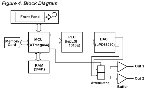
Figure 4 shows a block diagram of the AG1200 Arbitrary Wave-form Generator. This type of generator is ideal for creating a wide range of applications that require arbitrary waveforms. Fig. 4 Block Diagram of the AG1200 CREATING WAVEFORMS Arbitrary waveform generators must define waveforms. The

Arbitrary waveform generator block diagram
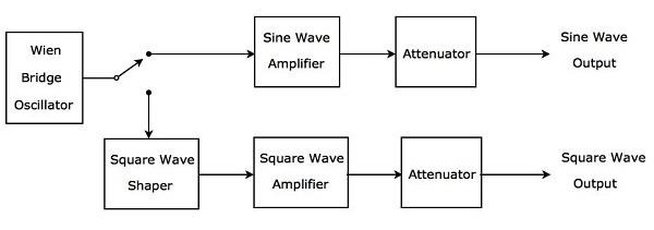
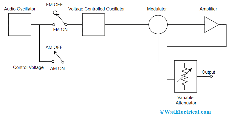
A block diagram of a simple sine wave/ square wave AF signal generator is given below: The Audio Frequency generators are most commonly used for checking the response of audio equipment, these instruments are also used for measuring distortions in any other equipment and have the capability to produce a distortion of 0.0001% by a simple audio ... An arbitrary waveform generator (AWG) is a piece of electronic test equipment used to generate electrical waveforms. These waveforms can be either ... Arbitrary Waveform Generator Demonstration The TSW3070 is an evaluation module (EVM) that shows how to use an active interface with the current sink output of the DAC5682Z. The EVM includes the DAC5682Z for digital-to-analog conversion, an OPA695 to demonstrate an active interface implementation using a wide bandwidth operational amplifier
Arbitrary waveform generator block diagram. Start continuous—Configures the signal generator to generate the waveform continuously and starts the generation. In this mode, the Express VI returns immediately after starting the generation. To stop the generation, drop another instance of the Express VI on the block diagram, select the same signal generator, and configure it to Stop ... Configures and runs National Instruments RF signal generators using NI-RFSG to produce an arbitrary waveform signal. You must place at least two NI-RFSG Express (Arbitrary Waveform) VIs on the block diagram for successful generation. Select Start generation for the generation mode in the first Express VI to start the continuous generation. Arbitrary Waveform Generator for SMIQ ... Fig. 2.14 Basic block diagram of SMIQB60. The I/Q samples are loaded by the host computer via the DATA IN interface to the DSP which passes them into a non-volatile FLASH RAM. The latter is organized in 22 blocks of 64ksamples, each. At least one block is occupied by A simple block diagram of a 73 GHz configuration is shown in Figure 5 that can be used for 5G RF, microwave and millimeter-wave signal generation and analysis. The hardware configuration ... M8190A AXIe 12 GS/s arbitrary waveform generator . Find us at www.keysight.com.
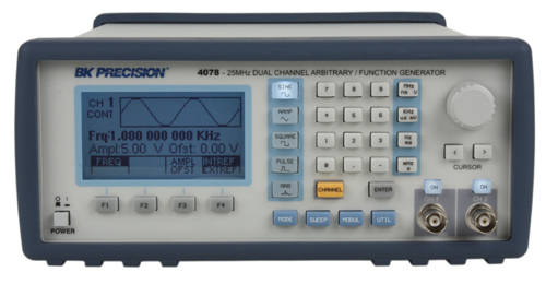
Figure 1: an e.g. Block diagram of a digital waveform generator (DWG) for a non-linear compressed pulse 1) (interactive picture) Digital Waveform Generation The desired waveform may be described by a mathematical function, and each discrete value of the function is stored as a digital word in a memory. Figure 2, the block diagram of the pulse generator is illustrated. The reconfigurable arbitrary waveform generator (RAWG) consists of a personal computer (PC) for config- uration through an USB 2 ... The NI ELVISmx Arbitrary Waveform Generator can generate sine, triangle, square, and sawtooth waves. The default value for this control is Sine. Test signals can only be used in the Express VI dialog box. When running the NI ELVISmx Arbitrary Waveform Generator Express VI, you must supply an input signal to generate a waveform. For example, the following diagram shows some of the special waveforms available in the B&K Precision 408X generator series: Although DDS generator models 4084-4087 do not provide a user programmable arbitrarily waveform memory, it provides users with the ability to output complex waveforms which is typically the domain of AWGs.
Arbitrary Waveform Generator Note: Unless otherwise indicated, this manual applies to all Serial Numbers. Page 1 (Service Guide) ... Schematics Chapter 8 contains the function generator's block diagram, schematics, disassembly drawings, and component locator drawings. For information on using the Phase-Lock Option for the 33120A, refer to The AWG16 is a 16 bit Arbitrary Waveform Generator for high-speed / high resolution waveform generation. The fully differential signal path from the DAC all the way to the outputs ensures an exceptional high signal quality. Despite the emphasis on signal quality the AWG16 also has a very good DC accuracy. The limitations of an Arbitrary Waveform Generator are the input voltage range, the characteristics of the DAC used to create the signal, and the performance characteristics of the device feeding data to the DAC. The quality of the generated waveform is directly related to the sample rate and resolution of the DAC module being used. 1.2 DAC Example of an arbitrary waveform generator. ... Ideally, you'll have product documentation including schematic, block diagram, and parts list with component values and parts numbers. If that information is not unavailable, it will be necessary to follow wiring and circuit board traces to locate the stages. Their placement may not seem logical ...
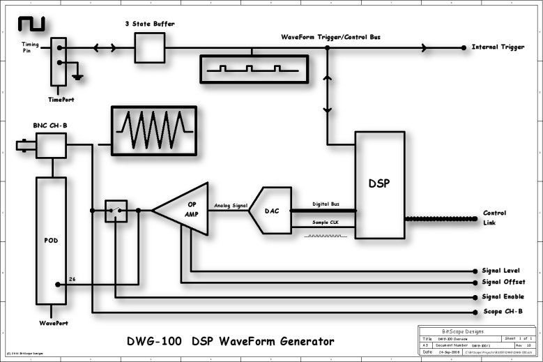
Dsp Waveform Generator
RF vector signal generators (VSG) use a dual arbitrary waveform generator (AWG) to generate baseband I (in-phase) and Q (quadrature) waveform signals and controls the playback sequence of waveform segments that have been written into the memory located in the internal baseband generator. Like an MP3 player that converts an audio file to an ...
A Reconfigurable Arbitrary Waveform Generator Using Pwm Modulation For Ultrasound Research Biomedical Engineering Online Full Text
Output — Arbitrary Waveform Generator . Note that all channels have identical output structure. Figure 1. M3302A output functional block diagram. Source: Keysight.com. Channel 1 output Channel x Amplitude DAC Channel x Channel n Channel 1 Dual arbitrary waveform generator (AWGx) LPF . Amplitude modulator AM(FGx. OffsetPhase. Function ...
Signal Generators
ADI's arbitrary waveform generator solutions will be introduced below, emphasizing applications with bandwidth below 300 MHz. By applying ADI's advanced DAC technology, lower stray and noise label can be achieved. For signal modulation, a few nice high-speed amplifiers are recommended, as well as some high precision ADC's and DAC's applications ...
Dds Function Generator
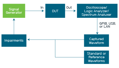
Figure 27 shows a block diagram of a test scenario where a signal generator produces a series of different signals conditional on digital control signals coming from the UUT. With scripting, a signal generator can respond to these digital control signals on the fly, without stopping generation of its waveform.
Using Fpga To Implement A N Channel Arbitrary Waveform Generator With Various Add On Functions Semantic Scholar
High-Bandwidth Arbitrary-Waveform Generator Reference Design: DC or AC Coupled, High-Voltage Output 1 System Overview In the TIDA-00684 reference design, a quad-channel TSW3080 evaluation module (EVM) has been developed to show how to use an active amplifier interface with the DAC38J84 device to demonstrate an arbitrary-waveform-generator front ...

Arbitrary Waveform Generator Using Dac And Dma
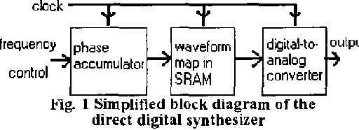
The basic block diagram of the DDS based arbitrary waveform generator is shown below. DDS frequency synthesizer as used in an arbitrary function generator, AFG . The operation of the DDS within the arbitrary function generator can be envisaged by looking at the way that phase progresses over the course of one cycle of the waveform.

Ad9102 Datasheet And Product Info Analog Devices
An Arbitrary Waveform Generator, AWG, or ARB is a specialised form of function generator that is able to generate waveforms from a set of values entered. Signal generator types: Signal Generator Basics RF signal generator Function generator Pulse generator. Arbitrary waveforms generators can also be referred to by their initials, AWG, and ...

Direct Digital Synthesis Wikipedia
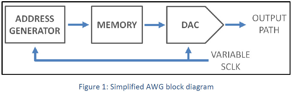
A digital block provides a good way to build an arbitrary waveform generator. This device periodically generates samples from a table; changing the table contents changes the output waveform. We will concentrate here on the digital design; the samples can be sent to an analog/digital converter for conversion to an analog waveform. As shown in ...
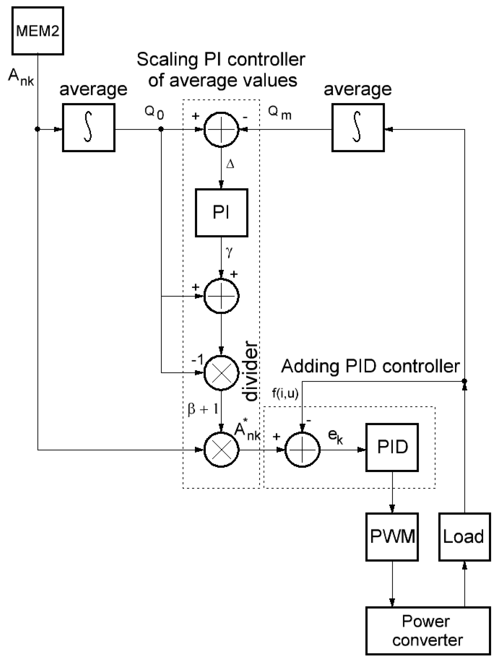
Instruments Free Full Text Smart Arbitrary Waveform Generator With Digital Feedback Control For High Voltage Electrochemistry Html
Function arbitrary waveform generators: direct digital synthesishttp://www.keysight.com/find/trueformFunction Generators often use direct digital synthesis t...
Awg18 18 Bit 300 Ms S Arbitrary Waveform Generator Applicos
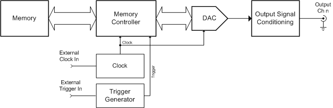
1 provides a block diagram for the interface between the Memory HiCorder MR8847A and a waveform generation module. Each measurement module includes ROM to which.6 pages

600 Mhz Arbitrary Waveform Generator Zurich Instruments
TSW3070EVM: Amplifier Interface to Current Sink DAC - Arbitrary Waveform Generator Demonstration 2 Block Diagrams 2.1 System Block Diagram Figure 1 shows the functions on the TSW3070EVM board. The Texas Instruments ICs are listed on the board for reference. Figure 1. Block Diagram 3 Key Texas Instruments Components 3.1 CDCM7005
Awg Introduction Spectrum
Block Diagrams 102 Front Panel Diagrams 103 2 . ... This synthesised programmable arbitrary waveform generator has the following features: • 1, 2 or 4 independent arb channels ... Arbitrary waveforms may be defined with 12 bit vertical resolution and from 4 to 65536 horizontal

The Difference Between Arbitrary Function Generators And Arbitrary Waveform Generators
Jun 16, 2017 — IT'S hard to beat arbitrary waveform generators (AWG) for convenience ... As this simplified block diagram of the DAC in a Tektronix AWG5200 ...

The Difference Between Arbitrary Function Generators And Arbitrary Waveform Generators
The AWG20 is a 20 bit Arbitrary Waveform Generator for medium-speed / high resolution waveform generation. The module combines an excellent dynamic performance with a very high DC accuracy. The module features differential outputs with a programmable common-mode voltage.

Common Signal Sources And Their Differences Keysight Blogs
Arbitrary Waveform Generator Demonstration The TSW3070 is an evaluation module (EVM) that shows how to use an active interface with the current sink output of the DAC5682Z. The EVM includes the DAC5682Z for digital-to-analog conversion, an OPA695 to demonstrate an active interface implementation using a wide bandwidth operational amplifier
1
An arbitrary waveform generator (AWG) is a piece of electronic test equipment used to generate electrical waveforms. These waveforms can be either ...
Function Generator Arbitrary Function Generators Tektronix
A block diagram of a simple sine wave/ square wave AF signal generator is given below: The Audio Frequency generators are most commonly used for checking the response of audio equipment, these instruments are also used for measuring distortions in any other equipment and have the capability to produce a distortion of 0.0001% by a simple audio ...
1
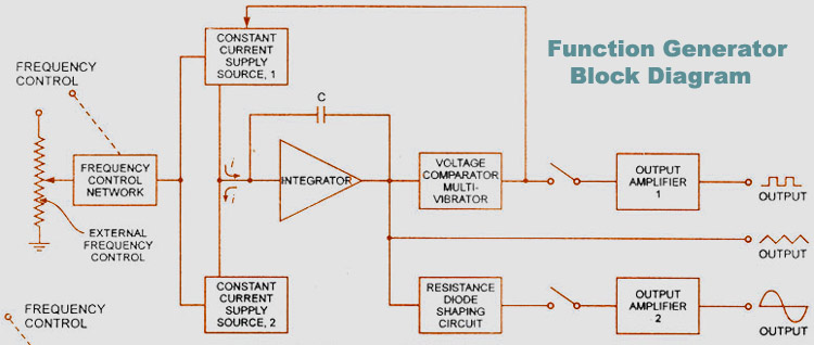
Signal Generator Block Diagram Circuit Types Applications

Af Sine And Square Wave Generator

Block Diagram Of The System A Digital Signal Is Generated By A Download Scientific Diagram

Design And Analysis Of A Low Cost Wave Generator Based On Direct Digital Synthesis

Block Diagram Of The Reconfigurable Arbitrary Waveform Generator Download Scientific Diagram

Simplifying Signal Generation Using Arbitrary Waveform Generators

Arbitrary Waveform Generator An Overview Sciencedirect Topics

Consider The Source Part 1 What Is A Phase Locked Loop Keysight Blogs
Multi Nyquist Zones Operation Solution Note

Design Of A Powerful Signal Generator Output Stage Analog Devices
2
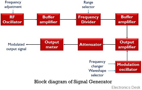
What Is A Signal Generator Definition Block Diagram And Working Of Signal Generator Electronics Desk
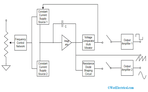
Signal Generator Block Diagram Circuit Types Applications
Arbitrary Waveform Generator Wikipedia
Arbitrary Function Generator Tactical Humanities Lab

Choosing A Waveform Generator The Devil Is In The Details Edn

Real Time And Arbitrary Waveform Generation Mode Which One Is Right For Your Test

Variable Clock Arbitrary Waveform Generator Awg Electronics Notes

Types Of Waveform Generators With Applications

Real Time And Arbitrary Waveform Generation Mode Which One Is Right For Your Test

Function Generator E Manuals
All You Need To Know About A Signal Generator And How To Select One

Arbitrary Waveform Generator An Overview Sciencedirect Topics
1
Comments
Post a Comment