42 fire alarm circuit diagram
A fire alarm system in which components are used, in whole or in part, in common with a non-fire signaling system. ... The circuits of the fire detection and alarm system are designed to operate under normal and single fault conditions; details of the a Siemens Building Technologies, Inc. SIEMENS Alarm 8. The simple fire alarm system is one of the innovative solderless breadboard projects. This fire alarm project block diagram consists of thermistor, ...
Overheat Detector Alarm/Switch Schematic Circuit Diagram. At the heart of this circuit is a precision integrated temperature sensor type LM35 (IC1), which provides an accurately linear…. Read More ». Admin June 1, 2019. 0 38.

Fire alarm circuit diagram
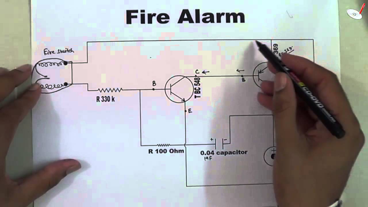
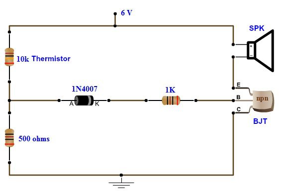
You can see the circuit diagram of fire alarm in above figure. When there is no FIRE, thermistor remains at 10k ohm. And transistor remains at ON state because there is sufficient voltage across the base-emitter of transistor, which makes it ON. When the Transistor is ON, Pin 4 (RESET) is connected to the Ground, and when Reset pin is Grounded, 555 IC doesn't operate. Now when we start heating ... Todays Circuits Engineering Projects Fire Alarm Circuit. Smoke Detector Circuit Diagram Scientific. Fire alarm circuit automatic alram using transistor ic and ardino smoke detector diagram thermistor 555 timer envirementalb com todays circuits engineering projects simple optical full with explanation light sensitive diy mq02. Wiring. Simple Wiring Diagrams for Mains Powered Fire and Carbon Monoxide Alarms. Wiring diagrams are included in the instructions supplied with all alarms, but here are a few basics. All mains powered alarms and accessories need a mains supply that is taken from a permanent live feed – for example a lighting circuit. Mains Powered Smoke & Heat Alarms – hard-wired interconnection. All of Aico’s ...
Fire alarm circuit diagram. The fire alarm equipment that supplies power-limited fire alarm cable circuits must be marked to indicate each circuit that is a power-limited fire alarm circuit. Per NEC article 760.30, the fire alarm circuits must be marked at terminal and junction locations. In this article, we will study the method to built a simple fire alarm by using a 555 Timer IC. It will detect the fire and sound a buzzer. Fire Alarm Circuit. A thermistor is the heart of this circuit. This sensor will be used to detect the fire. It is a resistor that is very sensitive to temperature. Simple Fire Alarm Circuit using Thermistor and Op-Amp - Circuit Diagram, Components Required, Project Construction, Output and Working of the Project. For mo... Fire Alarm Circuit Diagram Using Thermistor And 555 Timer Ic. Hard Wired Vs Wireless Fire Alarm Systems News. Low Cost Fire Alarm Circuit Working Scematic. Simple Fire Alarm Circuit Using Thermistor Lm358. Smoke Detector Circuit. Light Sensitive Fire Alarm Diy Circuit Diagram With Full Explanation.
Fire Detection And Alarm Mini Project. Steps to build simple fire alarm circuit using thermistor detection system block diagram scientific schematic of the perfunctory and liberate operation essential protection for systems smoke detector transistor envirementalb com ldr what is a realpars functional ionization with interconnect. The initiation of a fire alarm system includes all the devices and circuits that send a signal to a fire alarm to provide the status of a protected space or the existence of a fire. Initiation devices include, but are not limited to heat detectors, smoke detectors, water flow switches, manually actuated devices, and pressure switches. Description: Gsm Based Fire Alarm System | Circuits4You regarding Fire Alarm System Schematic Diagram, image size 821 X 595 px, and to view image details please click the image.. Here is a picture gallery about fire alarm system schematic diagram complete with the description of the image, please find the image you need. Types Continued Initiating Device Circuits (IDC) A circuit where Automatic or Manual Initiating Devices are connected and the signal does NOT identify the individual device operated. Performance shall be based upon wiring Class (Note the old Class & Style has been replaced with Class only) Alarms must activate NACs and Control circuits within 10 seconds
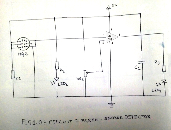
Block Diagram of Fire Alarm Circuit Using LM741. The thermistor is the main component which detects the fire by sudden change in the room temperature because of the heat generated by the fire. The thermistor will detect the heat and give the information to the LM741 OP-AMP. The op-amp will make the NE555 to generate pulse which has been given ... Fire alarm system wiring and equipment, including all circuits controlled and powered by the fire alarm system, shall be installed in accordance with the requirements of this Code and of NFPA 70 Article 760. Assortment of fire alarm system wiring diagram. A wiring diagram is a simplified standard photographic depiction of an electrical circuit. It reveals the components of the circuit as streamlined forms, and the power as well as signal links in between the devices. In the addressable fire detection system, the fire alarm wiring schematic diagram as described below: Each detector has 4 connections (2 inputs & 2 outputs) The connection is done in the detector body. The detector body is given an address (serial addressing). In the addressable fire alarm system the fire alarm control panel can detect if the fire detector is in fault condition or in fire ...
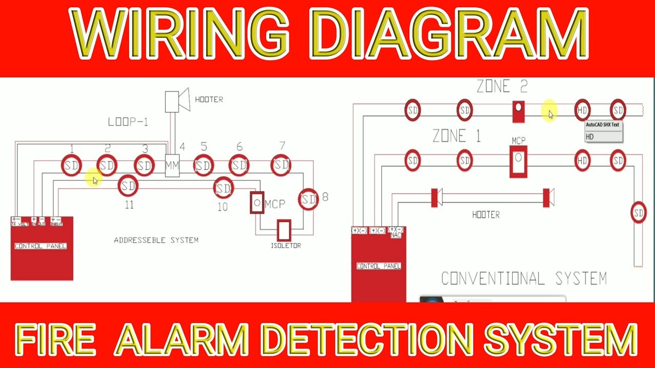
Types Of Fire Alarm Systems And Their Wiring Diagrams
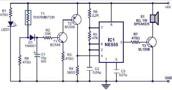
Schematic of the Fire Alarm Circuit. Timer IC NE555 (IC1) is wired as an astable multivibrator oscillating in audio frequency band. Switching transistors T1 and T2 drive multivibrator NE555 (IC1). The output of IC1 is connected to npn transistor T3, which drives the loudspeaker (LS1) to generate sound. The frequency of IC1 depends on the values of resistors R5 and R6 and capacitor C2. To ...
Fire Alarm Schematic Design Under Alarm Circuits 60508 Next Gr
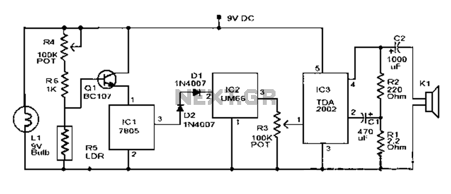
Here is a simple fire alarm circuit based on a Light Dependent Resistor (LDR) and lamp pair for sensing the fire. The alarm works by sensing the smoke produced during fire. The circuit produces an audible alarm when the fire breaks out with smoke. When there is no smoke the light from the bulb will be directly falling on the LDR.

Smoke Detector Alarm Circuit Diagram
Fire Alarm Control Units The fire alarm control unit (FACU), formerly called the fire alarm control panel (FACP), contains the electronics that supervise and monitor the integrity of the wiring and components of the fire alarm system. The FACU basically serves as the brain for the alarm system (Figure 14.2). It receives signals from
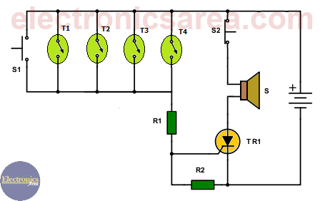
Fire Alarm Circuit Using Thermostats And Scr Electronics Area
Simple Fire Alarm Circuit designed by using 10K NTC (Negative Temperature Coefficient) Thermistor and timer IC 555, this circuit will produce buzzer sound when the temperature near thermistor raises beyond threshold, and this threshold limit can be varied by using variable resistor. This simple fire alarm circuit can be used as a indicator or warning circuit for excessive fire and temperature ...
Simple Smoke Detector Circuit
#CircuitsDIYFind Full Project Description & All Useful Material Including• Circuit Diagram / Schematic• Hardware / Component List• Codes / Algorithm• Datashe...
Smoke Alarm Circuit Troubleshooting
Related Post: Difference Between Conventional and Addressable Fire Alarm; Wiring Diagram of Heat Detector in Home (AC) Conventional Fire Alarm System. In a conventional fire alarm system, all devices such as detectors, sounders and call points are connected to the control panel through separate wire or cable instead of shared one. In other words, the first end of the wire is connected to the ...
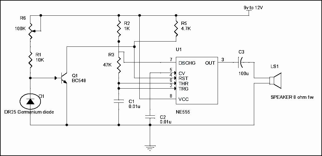
Simple Fire Alarm Circuit Using Thermistor Germanium Diode And Lm341
Addressable Fire Alarm Wiring Diagram Diagrams For. By Delores Rone on February 14 Each type of switch has a different symbol and so do the various outlets. There are symbols that show the location of smoke detectors, the doorbell chime, and thermostat. addressable fire alarms systems typical wiring diagram. addressable fire. examine how an addressable fire alarm system works. Firstly, every ...

Simple Fire Alarm Circuit 3 Steps Instructables
Fire Alarm Circuit Classes 2007 NFPA 72, 6.4.2.1 Class. Initiating device circuits, notification appliance circuits, and signaling line circuits shall be permitted to be designated as either Class A or Class B, depending on their performance during nonsimultaneous single circuit fault conditions as specified by the following:

Fire Alarm Circuit Using Lm358 Hackster Io
Circuit Diagram Circuit Operation. The fire alarm diagram can be seen in the figure above. If no FIRE occurs, the thermistor will remain at 10 K. And transistor is left in ON since the base-emitter of the transistor has sufficient voltage, rendering it ON.

Schematics Com Photoelectric Smoke Detector
fire command room levelb1 level 3 level 4 level 5 level 6 wire trough 120v. ac power, 3 #12 thwn cu to house panel, connect to dedicated fire alarm circuit. 120v. ac power, 3 #12 thwn cu to house panel, connect to dedicated fire alarm circuit. inx2 matchline (fa7.02) matchline (fa7.01) garage elec rm garage 729 level 7 (2) 2" conduit 1" conduit ...
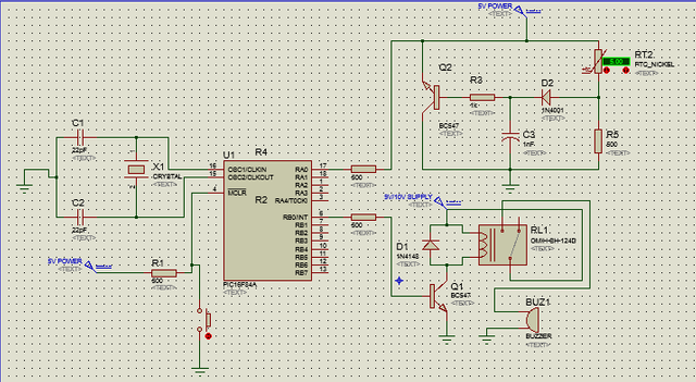
Fire Alarm Using Pic16f84a All Step By Step Procedures Steemit
The information shown for each control panel includes wiring diagrams and circuit tables. The circuit type is designated with a letter, (A-Z). In the tables, the letters are listed on the left, on the drawings, letters appear in red diamonds. Once the circuit type (A-Z) is identified, the user can proceed to the Paige Catalog included in this ...

Smoke Alarm Circuit
12+ Simple Fire Alarm Circuit Diagram. A smoke detector's purpose is a simple one, to give you ample notification in case of a fire in. Makes an alarm when the fire brakes. The basic idea behind the loop system is that in case of short circuit fault, only a small portion of the system. This is simple transistor based motorcycle alarm.
1
A wiring diagram is a simplified conventional pictorial depiction of an electrical circuit. Nicet certified fire alarm systems the gamewell company is the oldest fire alarm company in the world. Afc 1000 addressable fire panel wiring diagram type of circuit voltage type power type. 2 afc 1000 ins allation manal 5403649 re.

Sensitive Fire Alarm Mohan S Electronics Blog
How to Wire a Fire Alarm System with Detectors – Wiring Installation Diagrams Fire Safety Training. eeetblog. Electrical Technology. 184k followers.
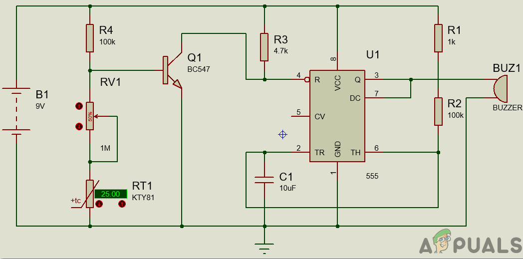
How To Make A Simple Fire Alarm Circuit Appuals Com
Fire alarm control units use new communication technologies, such as Ethernet, fiber optics, and wireless, which do not fit in the 'copper' wiring methods.". As always, contractors must install all wiring, circuits and pathways in accordance with the NEC. Thus, the new chapter appropriately references specific requirements from the NEC.
Fire Alarm Using Thermistor 1 Multisim Live
Simple Wiring Diagrams for Mains Powered Fire and Carbon Monoxide Alarms. Wiring diagrams are included in the instructions supplied with all alarms, but here are a few basics. All mains powered alarms and accessories need a mains supply that is taken from a permanent live feed – for example a lighting circuit. Mains Powered Smoke & Heat Alarms – hard-wired interconnection. All of Aico’s ...

Fire Alarm Using Ic555 Simple Electronic Circuits Circuit Diagram Science Experiments
Todays Circuits Engineering Projects Fire Alarm Circuit. Smoke Detector Circuit Diagram Scientific. Fire alarm circuit automatic alram using transistor ic and ardino smoke detector diagram thermistor 555 timer envirementalb com todays circuits engineering projects simple optical full with explanation light sensitive diy mq02. Wiring.

Fire Alarm Circuit Using Transistor Envirementalb Com
You can see the circuit diagram of fire alarm in above figure. When there is no FIRE, thermistor remains at 10k ohm. And transistor remains at ON state because there is sufficient voltage across the base-emitter of transistor, which makes it ON. When the Transistor is ON, Pin 4 (RESET) is connected to the Ground, and when Reset pin is Grounded, 555 IC doesn't operate. Now when we start heating ...

How Does A Fire Alarm Work Quora

Types Of Fire Alarm Systems And Their Wiring Diagrams Fire Alarm System Fire Alarm Alarm System

Fire Alarm Circuit Diagram Using Thermistor And 555 Timer Ic

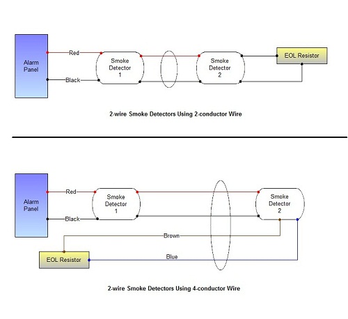
4 Wire Smoke Detector Wiring Tech Resource Online
Fire Alarm Circuit Using Ic 555 Gadgetronicx
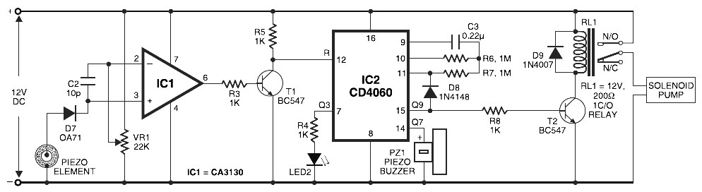
Pyroelectric Fire Alarm System Electronic Schematic Diagram

Fire Alarm Horn Strobe Wiring Diagram Best Of Fire Alarm System Alarm System Fire Alarm

Fire Alarm Wiring Diagram New Wiring Diagram Manual Call Point Valid In 2021 Fire Alarm System Fire Alarm Alarm System
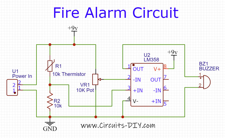
Fire Alarm Circuit Using A Thermistor Lm358 Op Amp Ic

Functional Block Diagram Of Ionization Smoke Detector With Interconnect Download Scientific Diagram
Fire Alarm System Wiring Diagram Conventional System Fire Alarm System In Hindi Youtube

Simple Fire Alarm Circuits At Low Cost Neotech
How Does A Fire Alarm Electronic Circuit Works By Raj Kumar Thenua Youtube

How To Make A Simple Fire Alarm At Home Heat Sensor With Explanation Using Transistor Bc 547 Youtube

Fire Alarm Circuit Using Thermistors

Fire Alarm Circuit My Engineering

Fire Alarm Using Thermistor Circuit Diagram And Instructions

Smoke Detection Circuit Diagram Download Scientific Diagram
Simple Fire Alarm Circuit Using Ldr

Electronics For All Fire Alarm Circuit Diagram Using 555 Timer Facebook
School Project Simple
Simple Fire Alarm Circuit Using Thermistor Germanium Diode And Lm341

Sensitive Fire Alarm Circuit Using Infrared Ir Led

Smoke Detector Circuit


Comments
Post a Comment