43 functional decomposition diagram engineering
This candidate will work with senior system engineers and architects to develop system engineering life cycle products for complex avionics hardware such as computers and network switches. The candidate is expected to leverage Model Based System Engineering (MBSE) tools and methods to support functional decomposition, architecture development ... Functional decomposition is a method used to design a detailed structure of components or modules of the software. Functional decomposition specifies the functions, activities, processes or actions that the component or module of the software has to perform. ... Requirement engineering is the process of collecting, validating and managing the ...
Decomposition in computer science, also known as factoring, is breaking a complex problem or system into parts that are easier to conceive, understand, program, and maintain.. Decomposition is a phenomenon common in the sciences of biology and chemistry. There are different types of decomposition defined in computer sciences: In structured ...
Functional decomposition diagram engineering
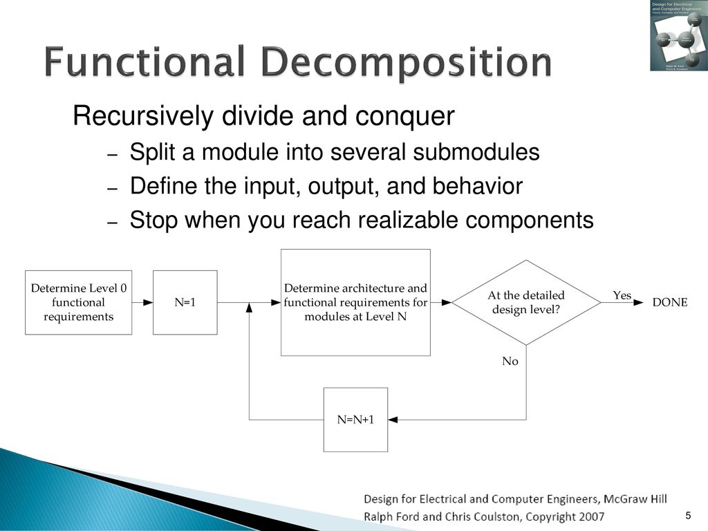
Level 0: Context Diagram. This DFD level focuses on high-level system processes or functions and the data sources that flow to or from them. Level 0 diagrams are designed to be simple, straightforward overviews of a process or system. Level 1: Process Decomposition A functional decomposition diagram is a picture that engineers draw to help them understand how all of the general tasks and subtasks in a design fit ...3 pages In functional decomposition of engineering systems, which is a method for analysing engineered systems, the basic idea is to try to divide a system in such ...
Functional decomposition diagram engineering. Your functional decomposition diagram s will be clearer if you show each level of refinement as a separate diagram. See, for example, Figure 3 and Figure 5, below. Separating Function from Implementation. Functional decomposition can be used in many engineering tasks, from conceptual design of a device to optimization of manufacturing workflow. Functional decomposition is especially important in programming. Once a diagram has been created, coding may begin as the programmer may then work on the most basic components first and then build ... Jan 29, 2018 — A functional decomposition describes a design concept, but it does not specify how each of the subtasks are implemented. The focus is on ...The Basic Idea · Separating Function from... · Flow of Material, Energy and... Model-based systems engineering (MBSE) is a formalized methodology that supports the requirements, design, analysis, verification, and validation associated with the development of complex systems. MBSE in a digital-modeling environment provides advantages that document-based systems engineering cannot provide.
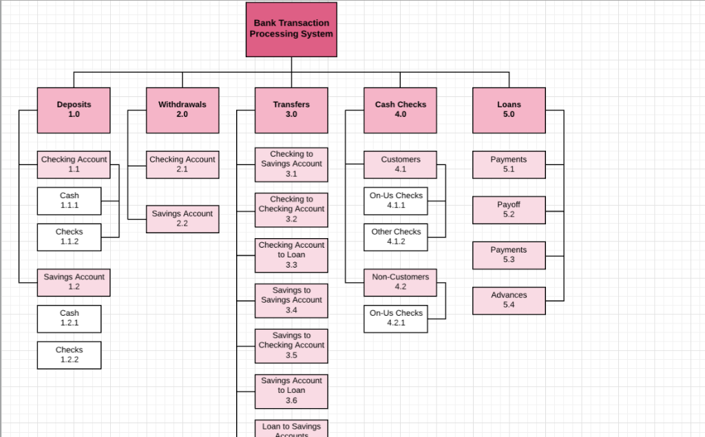
In engineering practice, the bearing fault signal is composed of a series of complex multi-component signals containing multiple fault characteristics information. In the early stage of fault sprouting and evolution, the fault features are easily disturbed by noise and irrelevant signals, eliminating the fault signals in the strong background noise. Functional Decomposition Diagrams . A functional decomposition diagram can be used to break down a system smaller and simpler parts. This will help you take a closer look at how the system functions. By breaking down the system or process thus, you will be able to easily understand the needs requirements. Photo by UX Ind on Unsplash. M odels are a way to represent the business requirement information descriptively and visually during the requirements analysis. Because the communication of business analysis information to stakeholders must be bi-directional, iterative and understandable, models can facilitate the communication with different groups of stakeholders in an initiative. You are now ready to create the functional decomposition diagram for the case-tracking system. What is the root process for the function decomposition diagram? What subsystems would you typically include? What processes would you show, and to what subsystem would they belong? Use this information to create a functional decomposition diagram.
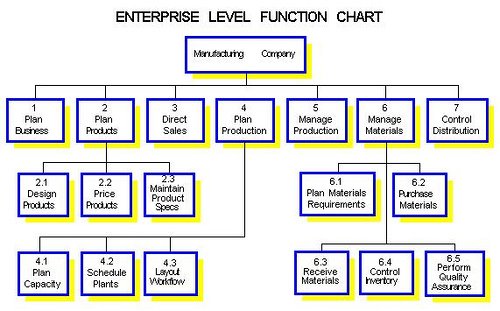
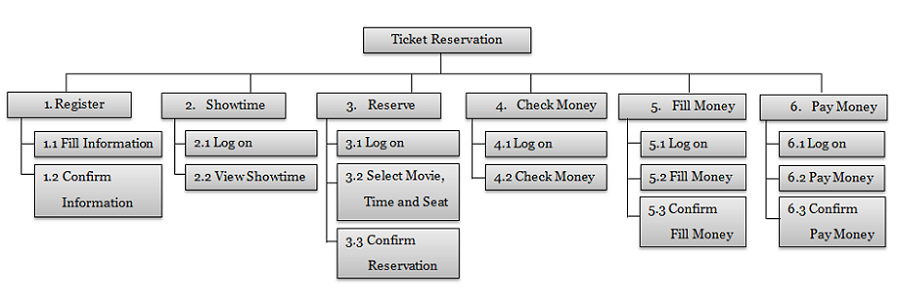
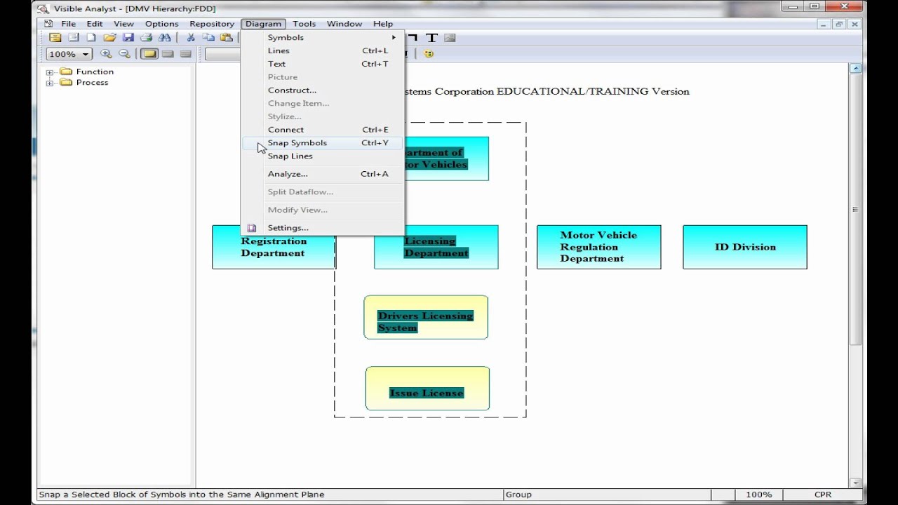
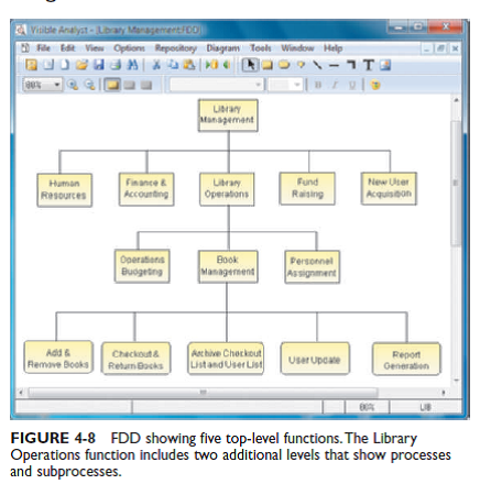
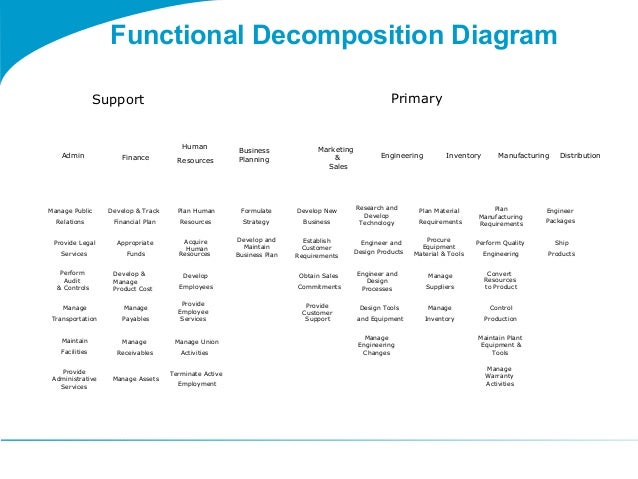
Our team utilized our culmination of knowledge acquired over five years of engineering studies to turn a "pen and paper" sketch into a functioning prototype; this project used engineering tools such as a Weighted Decision Matrix, Functional Decomposition Diagram, 3D CAD models, and Python coding. The functional decomposition diagram is a hierarchical structure that identifies, defines, and logically groups the business functions that are performed by the current system. It isolates the processes; it shows no data inputs, outputs, data stores, or sources of information. It undergoes functional decomposition to create small modules which are easier to analyze, design and code It is dependent on the decisions made in the defining stage of the development process Systems engineers are responsible for functional decomposition to technical requirements, the systems design and testing of that design. (QA or QC would spot check that.) Without this little effort is being applied to systems decomposition, dependencies, what-if scenarios, negative testing, or exceptions.
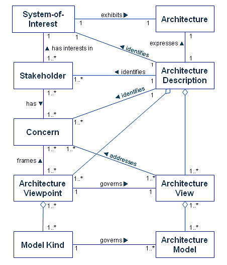
The Togaf Standard Version 9 2 Architectural Artifacts
The processes involved in requirements engineering are some of the most, if not the most, important steps in systems development. The need for well-defined requirements remains a critical issue for the development of any system. Describing the structure and behavior of a system could be proven vague, leading to uncertainties, restrictions, or improper functioning of the system that would be ...

Edge
Function is described in terms of the logical flow of energy, material, ... Functional Decomposition usually takes the form of a block diagram or an outline ...4 pages

Functional Decomposition An Overview Sciencedirect Topics
Basic operations of an ars need to be functional, and required to present diagrammatically. 15 Airline Reservation System Class Diagram. Airline reservation system is complex system and making it to be managed by software system instead of human will help to avoid a big percents of mistakes. Figure 1 shows a portion of a uml class model for a ...

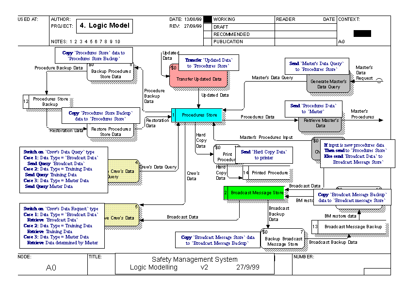
4 3 Logical Decomposition Nasa
Functional decomposition corresponds to the various functional relationships as how the original complex business function was developed. It mainly focusses on ...
Functional Decomposition Diagram Inventory System
SMC Systems Engineering Handbook - Figure15: Functional Analysis and Allocation. The Functional Analysis and Allocation bridges the gap between the high-level set of system requirements and constraints (from the Requirements Analysis) and the detailed set required (in Synthesis) to develop or purchase systems and implement programs.It is an integral part of both the Requirements Loop and the ...

Requirements Definition
Software Engineering MCQ Part 3. In the 3rd part of SE MCQs, you will get 100 multiple-choice questions. Of course, it will help you in interviews, your university viva & quizzes. ... Data-flow diagram (d) Module. Answer: b) Structure chart. 218. ... Functional decomposition (b) Transformation of a textual problem description into a graphic ...

Function Flow Block Diagram Ffbd
Functional. Structural Vs. Functional. System decomposition is necessary to be able to handle complexity, but thinking in the pure functional space is difficult. When working on an article about PLM and semiconductors, I got to review a favorite topic from my days in EDA development - verification versus validation.
Decomposing Diagrams Into Level 2 And Lower Hierarchical Levels
Ppt Software Design Powerpoint Presentation Free Download Id. System Design Document For A University Registration System. Functional And Non Functional Requirements Specification And. Functional Decomposition Diagram You Can Edit This Template And. 1 2 Software Design More Creative Than Analysis Problem.
Functional Decomposition Sam Ashok
Functional decomposition is a method used to design a detailed structure of components or modules of the software. Functional decomposition specifies the functions, activities, processes or actions that the component or module of the software has to perform. You can better understand the concept of functional decomposition with the help of an ...
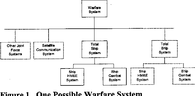
Functional And Physical Decomposition For Ship Design Semantic Scholar
Annotated functional decomposition. ... Computer Engineering and Informatics, School of Electrical Engineering, University of Belgrade, Belgrade, Serbia ... developed as an Eclipse IDE plugin that performs syntax and semantic checks along with the generation of UML sequential diagrams. The AFD Tool and its source code are available free of charge.
1
But it's not equivalent to a functional requirement. Otherwise, you'd end up with very complex diagrams that add little value to a textual list of requirements, and functional decomposition. Use cases represent "sets of offered behaviors" (UML definition of a use case) that correspond to user goals:

Hardware Software Design Requirements Planning Part 2 Decomposition Using Structured Analysis Embedded Com
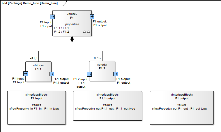
A block diagram showing functional decomposition diagram. Oct 08, 2021 · Structure of a UML Component Interface in Component Diagram. The Interface is a named set of public features. It separates the specification of functionality from its implementation by a class diagram or a subsystem. Functional decomposition diagram example. Aug 29, 2021 ...

Pin On Work Breakdown Structure Templates Wbs
Difference between Function Oriented Design and Object Oriented Design. 1. Function Oriented Design : Function oriented design is the result of focusing attention to the function of the program. This is based on the stepwise refinement. Stepwise refinement is based on the iterative procedural decomposition.

Mechanical Product Design Functional Decomposition In Concept Development Youtube
Systems Engineering, Part 3: The Benefits of Functional Architectures. From the series: Systems Engineering: Managing System Complexity. Functional, logical, and physical architectures are important tools for designing complex systems. We describe what architectures are and how they contribute to the early stages of a project.
Functions In Systems Model About Functional Decomposition In By Regis Casteran Seatwork Medium
Requirement Engineering is the process of defining, documenting, and maintaining the requirements. It is a process of gathering and defining services provided by the system. There are several steps in the requirements engineering process. Also, there are several uses of the requirement engineering process.

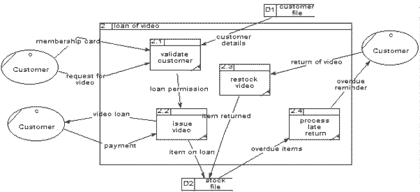
1 Data Flow Diagram 2 Outline Process Decomposition Diagrams Data Flow Diagram Dfd Ppt Download
In functional decomposition of engineering systems, which is a method for analysing engineered systems, the basic idea is to try to divide a system in such ...

Engineering
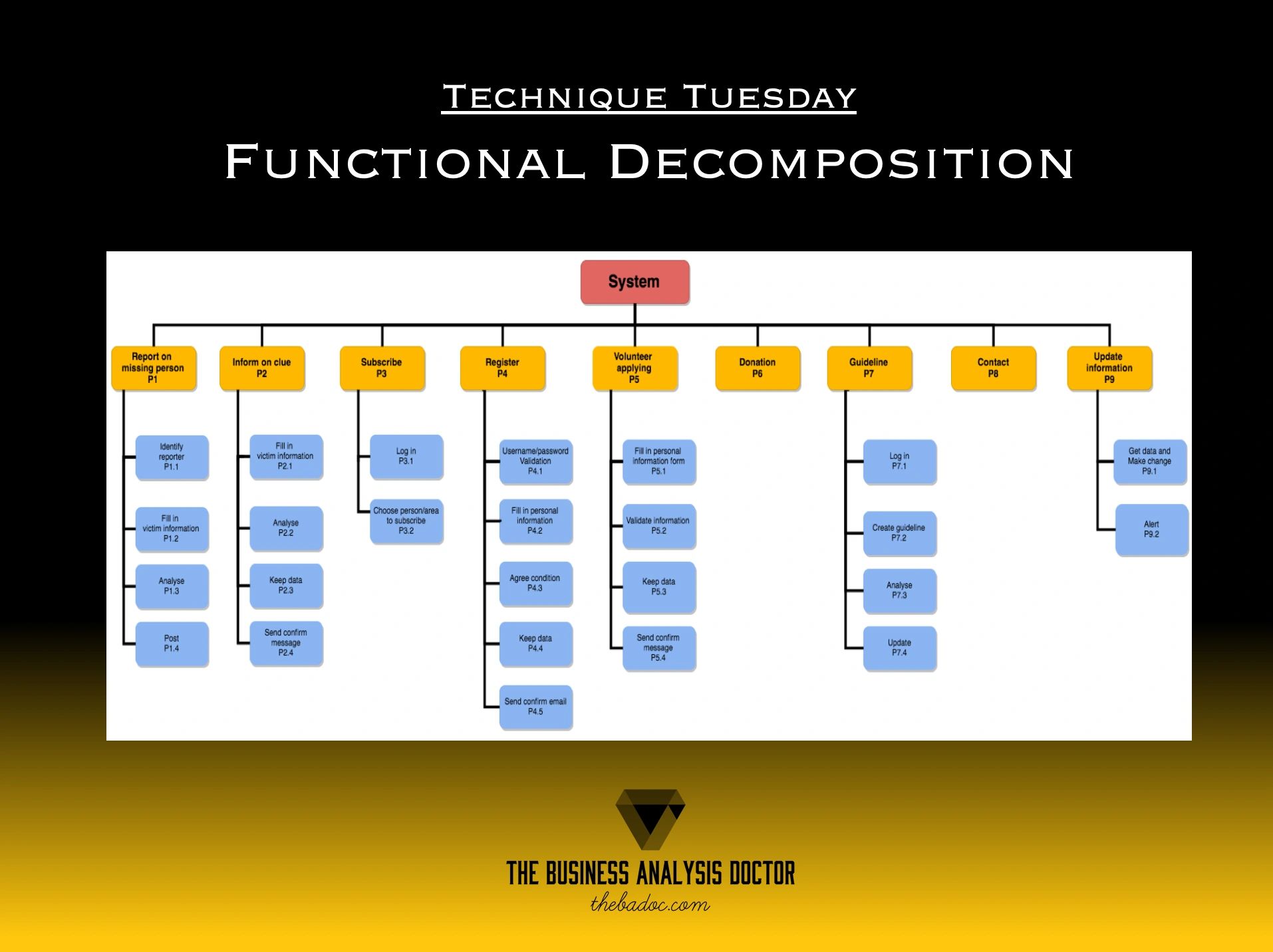
A functional decomposition diagram is a picture that engineers draw to help them understand how all of the general tasks and subtasks in a design fit ...3 pages
Functional And Non Functional Requirements Specification And Types Altexsoft
Level 0: Context Diagram. This DFD level focuses on high-level system processes or functions and the data sources that flow to or from them. Level 0 diagrams are designed to be simple, straightforward overviews of a process or system. Level 1: Process Decomposition
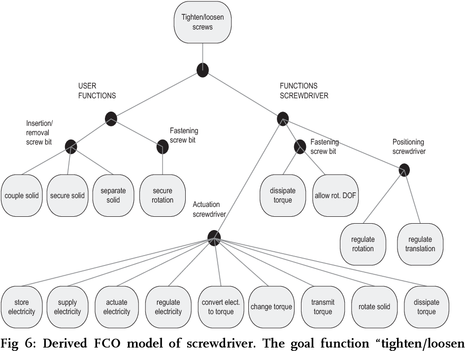
Figure 6 From Functional Decomposition On Rationality And Incommensurability In Engineering Semantic Scholar

Functional Decomposition Diagrams Fdds Youtube
Part 4 Consistency Between Functional And Logical Architectures Samares Engineering
Functional Decomposition Ppt Download

Functional Decomposition Diagram 2013 Itcs371 Sec2 Hamsik
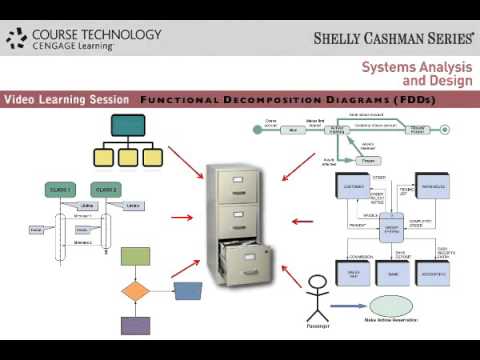
Functional Decomposition Diagrams Fdds Youtube
Create A Functional Decomposition Diagram For A Chegg Com

Functional Decomposition An Overview Sciencedirect Topics

Edge
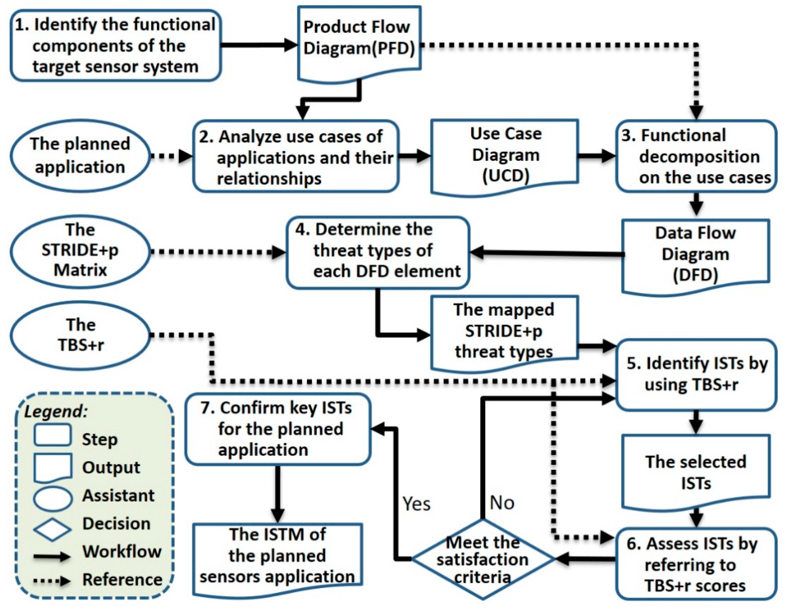
Inventions Free Full Text Determining Information Security Threats For An Iot Based Energy Internet By Adopting Software Engineering And Risk Management Approaches Html

Functional Decomposition An Overview Sciencedirect Topics

5 Functional Decomposition Diagram Itcs371 Dev Tutu

Functional Flow Block Diagram Wikipedia

Functional Flow Block Diagram Wikipedia

Functional Decomposition Structure Chart Software Engineering

Fmea Corner Decomposing System Functions To Lower Levels
Etutorial Brief How To Work With Functional Decomposition Diagrams Youtube

Functional Decomposition Youtube
2
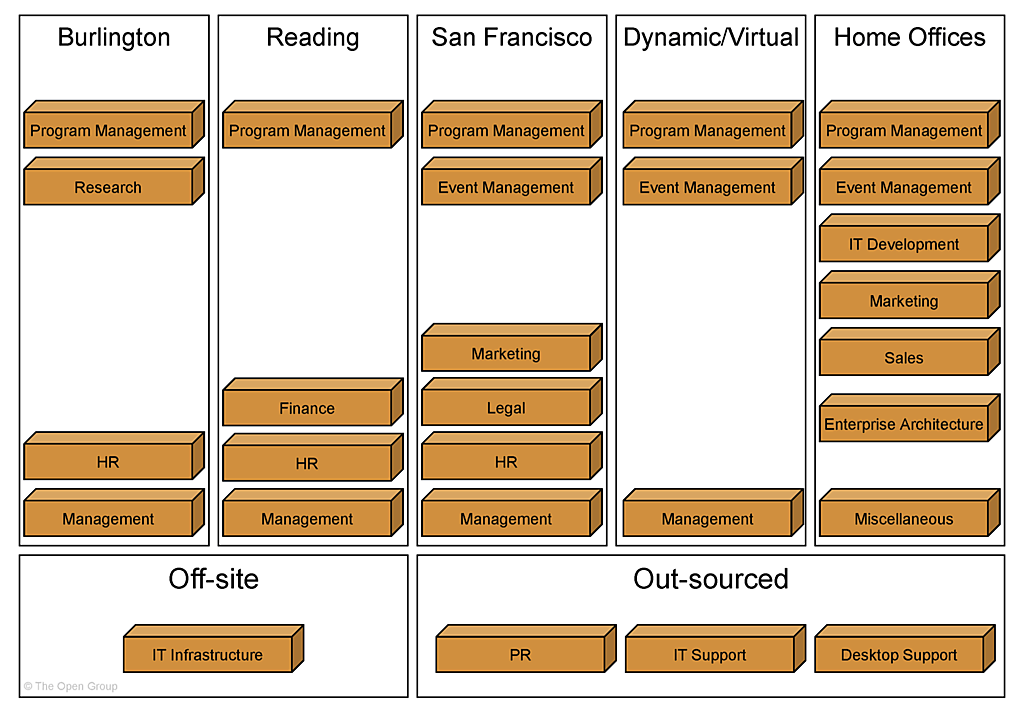
The Togaf Standard Version 9 2 Architectural Artifacts
Software Engineering With An Agile Development Framework Iteration Two Decomposition Wikibooks Open Books For An Open World

Edge
Functional Decomposition Deep Dive
Solved Create A Functional Decomposition Diagram Similar To The O Chegg Com
Togaf 9 Template Functional Decomposition Diagram
Comments
Post a Comment