39 control system block diagram examples
BLOCK DIAGRAM REDUCTION Block diagram is a pictorial representation of a control system showing inter-relation between the transfer function of various components. The block diagram is obtained after obtaining the differential and transfer function of all components of a control system. Figure 2.1 shows an element of the block diagram. Control Systems Block Diagram Dr. Juma Yousuf Alaydi. Block Diagram Reduction ... Block diagram components Figure 4: Block diagram of a closed-loop system with a feedback element . BLOCK DIAGRAM SIMPLIFICATIONS Figure 5: Cascade (Series) Connections Figure 6: Parallel Connections ... Example 1 R + _ _ + G 1 G 2 G 3 H 1 H 2 + + C. Example R ...
Draw the block diagram of the control system for the following cases: 1. Computer Disk Drive. 2. Video Game. 3. Student-Teacher learning Process. 4. A Human -Arm control system. 5. A control system for a twin-lift helicopter system. 6. Robotic microsurgical device. 7. An automobile cruise control system.
Control system block diagram examples
Worrying about how to solve block diagram reduction examples and finding transfer function then you are at right place watch this video till end and you will... The main goal of drawing a block diagram is to give an overview of the workflow that could be expected from the system post its completion. With the clear illustration, it becomes easy for the engineers to assess the smooth functioning of the process and to identify the existing elements (or the missing ones) that might obstruct, hinder, or unnecessarily delay the output. Block Diagram of Closed Loop Control System. In a closed-loop control system, a fraction of output is fed-back and added to the system's input. If H (s) is the transfer function of the feedback path, then the transfer function of the feedback signal will be B (s) = C (s)H (s). At the summing point, the input signal R (s) will be added to B (s ...
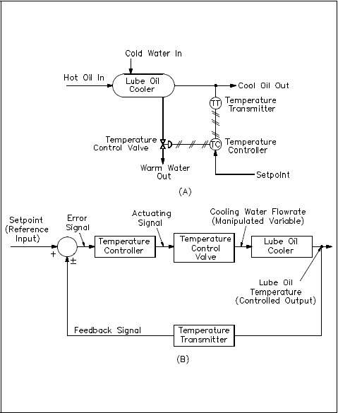
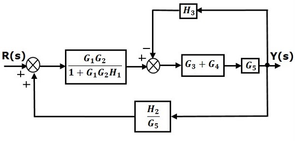
Control system block diagram examples. Recall the example of a cruise control system for an automobile presented in Fig-ure 8.4. This example is extended in Figure 8.17 to include mathematical models for each of the function blocks. This block diagram is first simplified by multiplying the blocks in sequence. The feedback loop is then reduced to a single block. Notice that the feedback Let us simplify (reduce) this block diagram using the block diagram reduction rules. Step 1 − Use Rule 1 for blocks G 1 and G 2. Use Rule 2 for blocks G 3 and G 4. The modified block diagram is shown in the following figure. Step 2 − Use Rule 3 for blocks G 1 G 2 and H 1. Use Rule 4 for shifting take-off point after the block G 5. = value of for that part of the block diagram that does not touch the ith forward path. We will now illustrate the use of Mason™s rule by several examples. Example W.1 Mason™s Rule in a Simple System Find the transfer function for the block diagram in Fig. W.2. SOLUTION From the block diagram shown in Fig. W.2 we have Forward Path Path Gain ... Example of Control System. Let us take an example in order to understand how a practical system can be converted in the form of a block diagram. Suppose we have a liquid level system as shown below and we have to represent this system in the form of a block diagram with the respective blocks for each element.
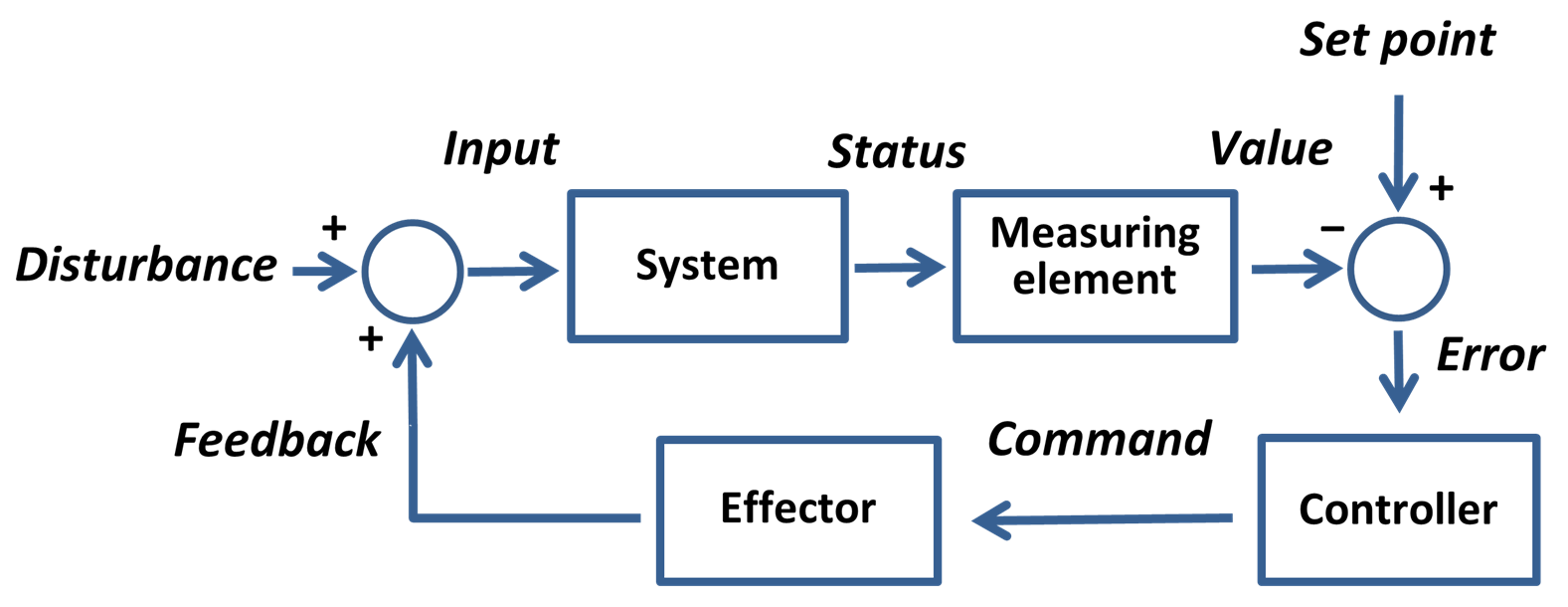
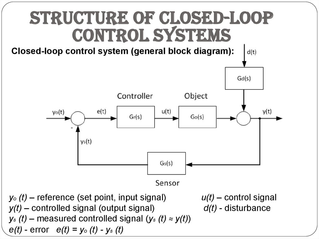
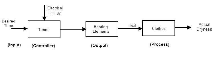
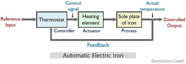
The open-loop control system block diagram is shown below. In the following diagram, the input can be given to the control system so that the required output can be obtained. However, this obtained output cannot be considered using this system for additional reference input. In the following system, it includes two blocks like controller as ... Closed-Loop Control System Block Diagram. When the control system includes a feedback loop, then the systems are known as feedback control systems. So the output can be controlled accurately by providing feedback to the input. This type of control system can include more than one feedback. Basic Elements of Block Diagram. The basic elements of a block diagram are a block, the summing point and the take-off point. Let us consider the block diagram of a closed loop control system as shown in the following figure to identify these elements. The above block diagram consists of two blocks having transfer functions G(s) and H(s). Examples of closed-loop control system. Here we will discuss the detailed operation of an automatic electric iron and a temperature control system. 1. Automatic Electric Iron. Consider an example of automatic electric iron which acts as a closed-loop system. The figure below represents the block diagram with major components:
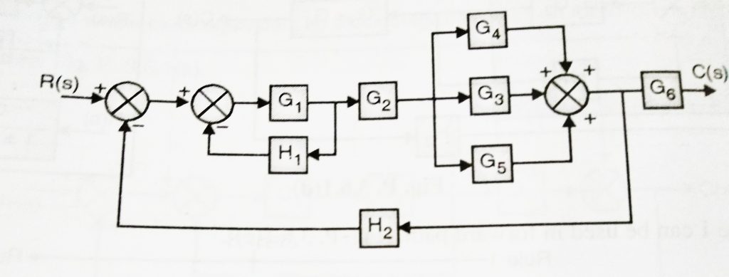
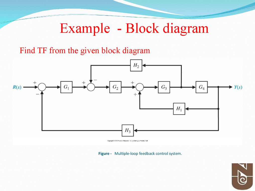
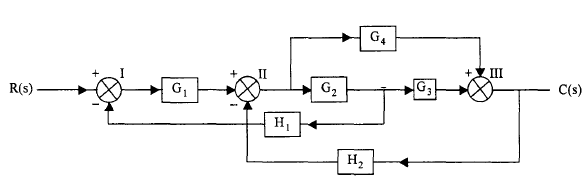
158 BLOCK DIAGRAM ALGEBRA AND TRANSFER FUNCTIONS OF SYSTEMS [CHAP. 7 Fig. 7-6 Continued 7.6 UNITY FEEDBACK SYSTEMS Definition 7.7: A unity feedback system is one in which the primary feedback b is identically equal to the controlled output c. EXAMPLE 7.6. H = 1 for a linear, unity feedback system (Fig. 7-7). Fig. 7-7 Any feedback system with only linear time-invariant elements can be put into ... Block diagram Examples. 1. Control System Engineering Kuntumal Sagar M. B.TECH (E.E) UID-U41000000484 Email: skuntmal@yahoo.com TOPIC BLOCK DIAGRAM EXAMPLES. 2. Example 9 Find the transfer function of the following block diagrams 2G 3G1G 4G 1H 2H ) (sY) (sR. 3. 1. Moving pickoff point A ahead of block 2G 2. ECE 680 Modern Automatic Control Routh's Stability Criterion June 13, 2007 3 where the coefficient a 1 is the result of multiplying a 1 by a 2 and subtracting a 0(0) then dividing the result by a 2.In the case of a second order polynomial, we see that Routh's Block Diagram • It represents the structure of a control system. • It helps to organize the variables and equations representing the control system. It is composed of: • boxes, that represents the components of the system including their causality; • Lines with arrows, that represent the actual dynamic variables, such as speed, pressure ...
The Basics Of Process Control Diagrams Technology Transfer Services
BLOCK DIAGRAM OF CONTROL SYSTEM Block Diagram: A control system may consist of a number of components. In order to show the functions performed by each component in control engineering, we commonly use a diagram called the ―Block Diagram‖. A block diagram of a system is a pictorial representation of the function performed by each component ...

Introduction To Control Systems 1 1 Tutorials Circuitbread
Block diagrams examples. 1D navigation Actor Transaction Diagram BER measurement on fibre optical system Block diagram line junctions Block diagram of Third order noise shaper in Compact Disc Players Control system principles Digital Signal Processing Library Double Arrows a la Chef EPC flow charts Fault tree Finite impulse response filter ...
Control Systems Block Diagram Reduction
•A Block Diagram is a shorthand pictorial representation of the cause-and-effect relationship of a system. •The interior of the rectangle representing the block usually contains a description of or the name of the element, gain, or the symbol for the mathematical operation to be performed on the input to yield the output.
Setpoint Control System Wikipedia
We have discussed in our previous article that for the easiness of analysis of a control system, we use block diagram representation of the control system.

Block Diagram Of Control Systems Transfer Functions Reduction Summing Points Electrical4u
K. Webb MAE 4421 3 Block Diagrams In the introductory section we saw examples of block diagrams to represent systems, e.g.: Block diagrams consist of Blocks-these represent subsystems - typically modeled by, and labeled with, a transfer function Signals- inputs and outputs of blocks -signal direction indicated by

Control System Principles Tikz Example
A Block Diagram is a shorthand pictorial representation of the cause-and-effect ... Canonical Form of A Feedback Control System: Example:.
1
An open-loop control system is one in which the control action is independent of the output. As the above figure has shown the elements of an open-loop control system can be divided into the following two parts: Controller and. Controlled process. A reference input signal is applied to the controller, whose output access actuating the signal.
Control System Solved Example Of Block Reduction Technique Electronicsguide4u
Example: Control system principles. An example of a control system with a feedback loop. Block diagrams like this are quite time consuming to create by hand. The relative node placement feature makes it a bit easier, but it works best when the nodes have equal widths. However, the results are quite pleasing and hopefully worth the effort.
Block Diagram Examples
block diagram shown in Figure 3-44. Figure 3-46 Block diagram of a system. Solution. The block diagram of Figure 3-44 can be modified to that shown in Figure 3-45(a). Eliminating the minor feedforward path, we obtain Figure 3-45(b), which can be simplified to that shown in Figure 3--5(c).The transfer function C(s)/R(s) is thus given by

Functional Block Diagram Wikipedia
10 Sept 2014 ... A block diagram is a pictorial representation of the cause and effect relationship between the input and output of a physical system. A block ...
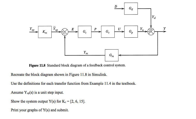
Solved 8p Sp Figure 11 8 Standard Block Diagram Of A Chegg Com
Control Systems: Block Diagram Reduction (Solved Example 1)Topics discussed:1. Solved Example based on the calculation of the overall ...
Control Systems Online Presentation
K. Webb ESE 499 3 Block Diagrams In the introductory section we saw examples of block diagrams to represent systems, e.g.: Block diagrams consist of Blocks - these represent subsystems - typically modeled by, and labeled with, a transfer function Signals - inputs and outputs of blocks - signal direction indicated by arrows - could be voltage, velocity, force, etc.

To Perform A Block Diagram Reduction Using Matlab Matlab Examples
Block Diagram in control systems. Any system can be described by a set of differential equations, or it can be represented by the schematic diagram that contains all the components and their connections. However, these methods do not work for complicated systems. The Block diagram representation is a combination of these two methods.

Instrumentation In A Nutshell What Is A Control System
Kamman - Introductory Control Systems - Block Diagram Reduction Examples - page: 5/8 Solution: When a system has more than one input signal, transfer functions are found by setting all but one of the input signals to zero.So, in this case, if both input signals are non-zero, then the output
Wescott Design Services Using Block Diagrams
Block Diagram of Closed Loop Control System. In a closed-loop control system, a fraction of output is fed-back and added to the system's input. If H (s) is the transfer function of the feedback path, then the transfer function of the feedback signal will be B (s) = C (s)H (s). At the summing point, the input signal R (s) will be added to B (s ...

Block Diagram Representation Of Control Systems Ppt Download
The main goal of drawing a block diagram is to give an overview of the workflow that could be expected from the system post its completion. With the clear illustration, it becomes easy for the engineers to assess the smooth functioning of the process and to identify the existing elements (or the missing ones) that might obstruct, hinder, or unnecessarily delay the output.

Explained Plc Block Diagram Programmable Logic Controller Etechnog
Worrying about how to solve block diagram reduction examples and finding transfer function then you are at right place watch this video till end and you will...
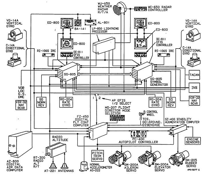
Figure 3 7 Integrated Flight Control System Block Diagram
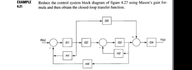
Solved Example 4 21 Reduce The Control System Block Diagram Chegg Com

Pdf 3 2 Block Diagram Components Of Motion Control System Semantic Scholar
Transformations Of Block Diagram Online Presentation
Chapter 2 Control Systems And Homeostasis
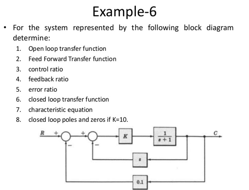
Solved Example 6 For The System Represented By The Chegg Com
Block Diagram Wikipedia
System Dynamics And Control Module 13c Example Block Diagram Reduction Youtube
Solution Define Open And Closed Loop Control Systems
What Is An Open Loop System Examples Advantages Disadvantages

Block Diagram Of The Process Control System Download Scientific Diagram

Modeling Simulation Of Dynamic Systems Lecture7 Block Diagram

Closed Loop System And Closed Loop Control Systems

Instrumentation In A Nutshell What Is A Control System
1
Block Diagram Of Computer Tutorial And Examples Edrawmax
Examples Of Closed Loop Control System Electronics Coach

7 General Block Diagram Of Control Loops A Open Loop And B Closed Download Scientific Diagram
What Is Block Diagram Anything You Need To Know Edrawmax Online

Chapter 1 Introduction To Control Systems Ppt Download

A Typical Block Diagram For A Control System With A Feedback Loop And Download Scientific Diagram
Control Systems Diagram
Comments
Post a Comment