43 accelerator pedal position sensor wiring diagram
Discussion Starter · #1 · Apr 2, 2012. Trying to replace the Accel Pedal Sensor on my 01 Ex 7.3l to accomodate a tuner. The wiring harness for the tuner that is supposed to plug into accelerator sensor is a 10 wire single head and the accelerator on the Exc is a dual head accelerator with two smaller heads and only 5 wires combined. C6 Corvette Wiring Diagram For Cam Position Sensor. ... The C6 Corvette accelerator pedal can be used with the harness. The GM.Camshaft Position Sensor Replacement Cost The average cost for a Chevrolet Corvette camshaft position sensor replacement is between $ and $ Labor costs are estimated between $61 and $ while parts are priced between $65 ...
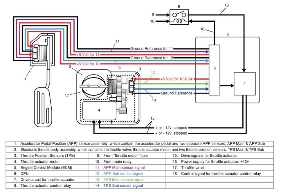
The two main sources of input data are the accelerator pedal position sensors (APP1 and APP2) and throttle position sensors (TPS). These sensors consist of a combination of two or more sensors, while the electronic control unit (ECU) uses an algorithm to validate the integrity of the signals.
Accelerator pedal position sensor wiring diagram
Troubleshooting the pedal position sensor is gonna be difficult. omgwtfbbq!, Apr 10, 2018 #6. Apr 10, 2018 at 12:18 PM ... I would download the schematics/block diagrams for the accelerator sensor circuits and start testing. ... it's possible you did something to a wire or have a bad ground (did you disconnect your battery or anything in the ... Sensor TPS y sus fallas | Lapps.es Portal Mécanica ... Car Wiring Diagram | Tankbig.com Trailer Wiring Diagram, Electrical Circuit Diagram, Kia. 29/11/2019 · Accelerator Pedal Position Sensor; Air Flow Meter Sensor; Throttle Position sensor; Below are the Pictures of Location of These Sensors ... Ford Car Sensors and Wiring Diagram Sensors and Wiring Diagram POWERTRAIN Sensors/Switches of Ford Focus 2011-2018. Jan 31, 2020 erwincsalarda.
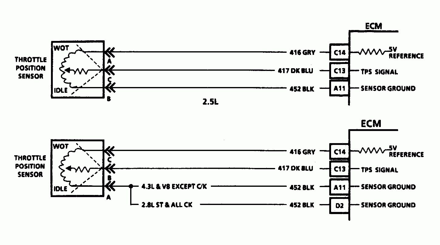
Accelerator pedal position sensor wiring diagram. Throttle Position Sensor Wiring Diagram - dodge throttle position sensor wiring diagram, ford throttle position sensor wiring diagram, gm throttle position sensor wiring diagram, Every electric structure is composed of various different components. Each part ought to be placed and linked to different parts in particular manner. Otherwise, the arrangement won't work as it ought to be. 12/11/2021 · 2019 Ram Classic 5.7 I rescued this gem from a owner who vandalized it. Every main harness was sliced! I rewired everything weeks ago to get it running. Problem is, I had to wire the apps straight to ground because I wasn't getting a ground through pin k167. Does anyone have or know where I can... 30/09/2017 · Ask for the wiring diagram for a MAF sensor on a 2000 Toyota Camry, without any other information and there is NO way anybody can help you. Wiring diagram for exterior lights. Let’s try this again. This time let’s say you’ve asked for a wiring diagram for your backup lights. Is it a 2.2 liter or 3.0 liter? On different units I have seen up to a 6 wire pedal, on that one my diagram shows it as a 3 wire. the plug has "B" as the top, that is sensor common. "A" is 8 volt power. "C" is accelerator position. From memory the resistance from "A" to "B" must be at least 1000ohms difference from full off to on, and "C" is idle position.
mounted on the accelerator pedal. The accelerator pedal assembly is serviceable to the extent that the APS/IVS switch can be replaced without replacing the complete assembly. Accelerator Position Sensor (APS) The ECM sends a regulated 5V signal through the ECM black chassis connector terminal 3 to APS connector terminal C. It must be performed each time harness connector of accelerator pedal position sensor or ECM is disconnected. 1. Make sure that accelerator pedal is fully released. 2. Turn ignition switch ON and wait at least 2 seconds. 3. Turn ignition switch OFF and wait at least 10 seconds. 4. Turn ignition switch ON and wait at least 2 seconds. checked spark by pulling plug wire replaced Intake air temp. sensor (although original one tested good) tried spare key i think that is it so far i think i know how to check the following and plan to tonight check o2 sensors accelerator pedal crankshaft position sensor it looks like the egr is deep, but i guess i should check that 21/04/2018 · DRL wiring diagram. The DRL system is different. The BCM looks at the input from the ambient light sensor. If it sees daylight and the parking brake isn’t set, the BCM provides ground to the control coil in the DRL relay. Once the control coil has ground, the contacts close and the relay provides power to the DRL lights.
Accelerator pedal position sensor wiring diagram wiring diagram is a simplified satisfactory pictorial representation of an electrical circuit it shows the components of the circuit as simplified shapes and the skill and signal links amongst the devices. Based on this information the load requested by the driver can be implemented immediately. 89 Chain accelerator pedal position sensor fault C-040 90 Correlation of sensors 1-2 accelerator pedal position C-040 ... im looking the complete engine wiring diagram & schematic thats color coded for my 4dr 1994 honda civic sedan has a D15b7 engine in it for now but someone cut up a few wires in diffrent areas. thank you very much its been ... Repair Guides | Automatic Transmission (2004) | Dtc P1705 - Accelerator Pedal Position Sensor Wiring Diagram. Wiring Diagram arrives with a number of easy to adhere to Wiring Diagram Instructions. It is intended to aid all of the average user in developing a correct system. These guidelines will be easy to understand and use. 03/11/2020 · The throttle position sensor is just another name for a potentiometer and it is located on the throttle body while the pedal position sensor is associated with the accelerator pedal system. The throttle position sensor detects the movement of the accelerator pedal and based on the signal, the PCM determines how much power the engine requires.
1.8t throttle pedal wiring | Club GTI
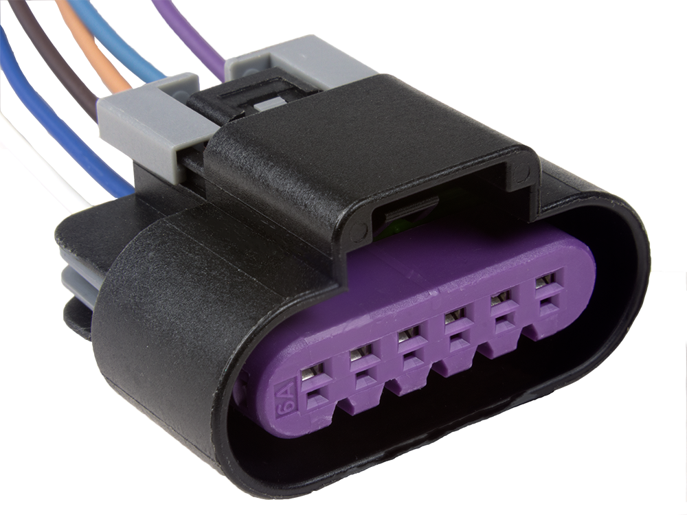
GM (CTS) Throttle pedal wiring. CGLockRacer GRM+ Member and HalfDork. 3/7/12 12:23 p.m. We want to use an electronic throttle pedal for a CTS on our driving simulators at work (they are pretty inexpensive). However I can't seem to track down a wiring diagram for the pins at the pedal sensor. It's a six pin male connector in a single row if that ...

Gm Accelerator Pedal Position Sensor Wiring Diagram For ...
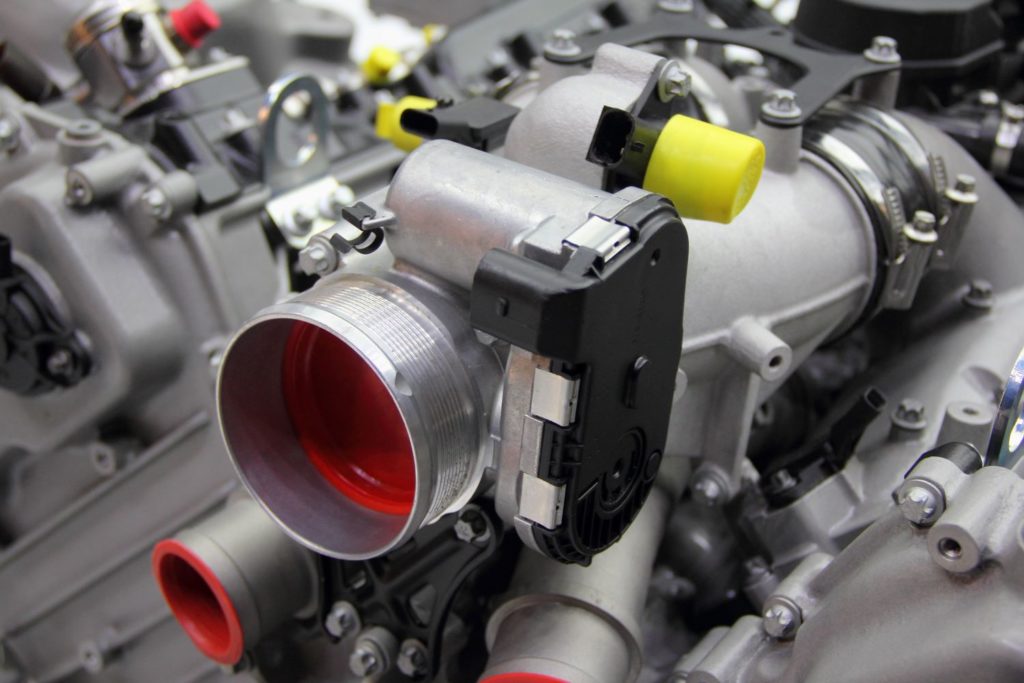
The accelerator pedal position sensor or AAP sensor is a part of the drive-by-wire system, which measures the position of the accelerator pedal. It tells the computer how far the accelerator pedal is depressed. It is mounted on the accelerator pedal or sometimes on the throttle body.

Repair Guides
Table Accelerator Pedal Sensor Wire Colors and Signals.Feb 16, · throttle loss Discussion in 'International Forum' started by sul, Feb 10, Feb 10 There is something wrong with the pedal sensor or related wiring. Throttle position sensor faults cause the engine to idle only and set a "Stop" engine light.

HOW DO I TELL IF MY THROTTLE POSITION SENSOR IS WORKING OR NOT
Drive by wire throttle wiring valve control module j338 tac system diagram 2007 2009 2 checking part position sensor understanding the efi process page 6 vag passive body diagnostic and repair harness replacement for 01 beetle problem help with 3 bolt 78mm dbw to 87mm 4 1 circuit audizine forums 8t pedal club gti ecu spitronics diy rewire tsb ...

2012 Maxxforce 13 Throttle Pedal Wiring Diagram
The car seems to still show some of the symptoms of the bad wiring (fluctuating idle, some smoke sometimes), so now I need to check if my throttle actuator is in good condition, so I am looking for the pin designation on the throttle actuator's plug, or the internal diagram (or schematic) to make electrical tests to see if the throttle position ...
Throttle position sensor wiring diagram. 08 int prostar isx cummins. Me and a mechanic new sensor and checking with
Here is a quick video on how to test a Throttle Position Sensor TPS with a multimeter. Also I show you how you can figure out what each wire on your sensor i...

Accelerator Pedal Position Sensor Wiring Diagram - easywiring
Gm Accelerator Pedal Position Sensor Wiring Diagram. Print the electrical wiring diagram off in addition to use highlighters to be able to trace the signal. When you use your finger or stick to the circuit together with your eyes, it is easy to mistrace the circuit. A single trick that I actually use is to printing the same wiring picture off ...
Toyota Venza: Throttle / Pedal Position Sensor / Switch "D ...
Dec 8, 2008 — C6 Tech/Performance - Accelerator pedal position (APP) sensor wiring diagram - Anyone help? - Hello everyone, I'm looking for a wiring ...

gray concrete statue of a man
accelerator pedal position sensor wiring diagram - You will need a comprehensive, skilled, and easy to understand Wiring Diagram. With such an illustrative guidebook, you'll be able to troubleshoot, prevent, and full your assignments with ease.
GM Gen III LS PCM/ECM: Electronic Throttle Equipment Guide
Accelerator Pedal Position Sensor Wiring Diagram - wiring diagram is a simplified satisfactory pictorial representation of an electrical circuit. It shows the components of the circuit as simplified shapes, and the skill and signal links amongst the devices. A wiring diagram usually gives counsel virtually the relative twist and concord of ...

Block-Neighborhood-Community: Diagram (n.d.) // Bertrand Goldberg American, 1913-1997
#Apps#Accelerator#pedal

Marina City: Finish Diagram (n.d.) // Bertrand Goldberg American, 1913-1997
03/05/2021 · Diagnostic trouble code (DTC) P2138 stands for “Throttle/Pedal Position Sensor/Switch D/E Voltage Correlation.” It is triggered when the vehicle’s engine control module (ECM) or powertrain control module (PCM) detects that the signals from the two throttle position sensors (or two accelerator pedal position sensors) do not correlate.

Accelerator Pedal Position Sensor Wiring Diagram - Diagram ...
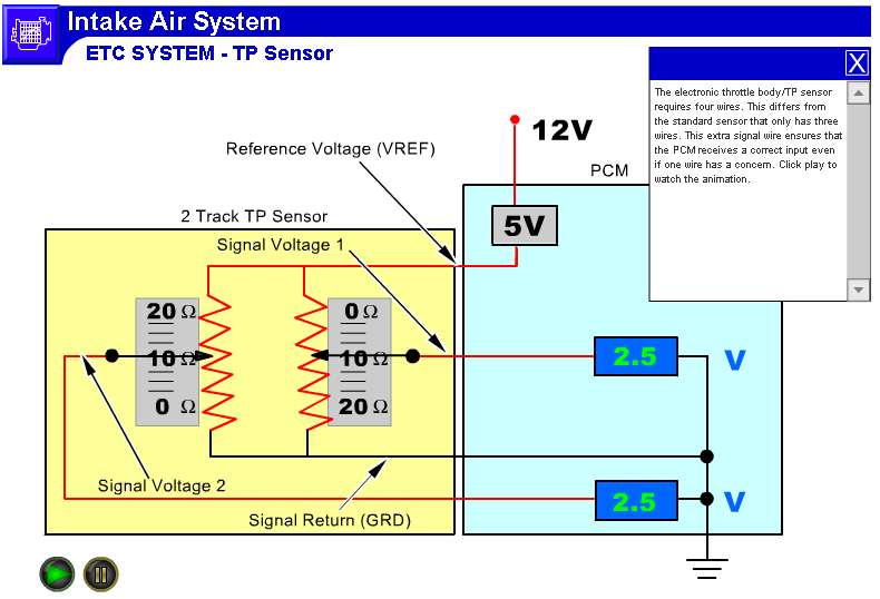
Waveform notes. In this example, the Accelerator Pedal Position (APP) sensor is of the potentiometer type. It receives two reference voltages from the Powertrain Control Module (PCM), having two ground wires and two signal wires that send a varying voltage back to the PCM relating to accelerator pedal position.

white and black rope on brown wooden table
As an example Fig. 1 shows the wiring diagram of a STILL forklift accelerator pedal circuit which enables an electronic control unit (ECU) to measure the ...
Testing Accelerator Pedal Position Sensors (APS)
Failsafe of Accelerator Pedal Position Sensor. The accelerator pedal position sensor comprises two (Main, Sub) sensor circuits. If a malfunction occurs in either of the sensor circuits, the ECM detects the abnormal signal voltage difference between these two sensor circuits and switches into the limp mode.
P0120 Code: Throttle/Pedal Position Sensor “A” Circuit ...
APPS- This harness supports the 2003 early Accelerator Pedal Position Sensor that was mounted on the front of the engine to the intake, the 2004 APPS mounted under the battery box and the 2005 late model Accelerator Pedal Position Sensor that was mounted on the accelerator pedal. You must use which ever APPS your ECM is programmed for.
13 Accelerator Pedal Position Sensor Wiring Diagram - Free ...
That the Accelerator Pedal Assembly is made up of 3 individual Position Sensors. Each one has separate signal, Ground, and 5.0 volt reference circuits. That APP Sensor 1's signal increases as the accelerator pedal is depressed, from below 1.1 volt at 0% pedal travel (pedal at rest) to above 2.1 Volts at 100% pedal travel (pedal fully depressed).
Throttle position sensor wiring | GMC Terrain, Equinox, and SRX Forum
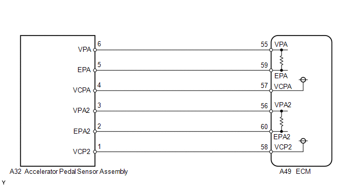
The accelerator pedal position sensor is mounted on the accelerator pedal to detect how much it is de-pressed. It has 2 sensor terminals (VPA and VPA2) to detect the accelerator pedal position and a malfunction ... WIRING DIAGRAM INSPECTION PROCEDURE 1 READ VALUE OF HAND-HELD TESTER(ACCEL POS #1 AND #2) (a) Connect the hand-held tester to ...

Untitled (Niagara Falls) (c. 1853) // Attributed to Platt D. Babbitt American, died 1879
P3002 - Accelerator pedal position (APP) sensor - transmission kick-down switch P3003 - Engine coolant heater relay 1, low output P3005 - Engine coolant heater relay 2, high output P3007 - Camshaft position (CMP) sensor - no signal P3008 - Camshaft position (CMP) sensor - signal limit exceeded P3009 - Fuel cooling pump relay - short to positive ...

silver and blue steel tool
Throttle Position Sensor Wiring Diagram - | Repair Guides | Connector Pin Identification | Heated. 17/9/2020 · a throttle position sensor, or tps, is a device which is used to monitor the air intake of an internal combustion engine. 30/6/2021 · the throttle position sensor is located on the throttle body and once it fails, code p2135 may get ...

black and brown electronic device
Ford F-Series V10 6.8L Engine Sensor Location Guide. Oct 8, 2020 erwincsalarda. Ford F-Series V10 6.8L Engine Sensor Location Guide Accelerator Pedal Position Sensor Air Flow Meter/Sensor Air Temperature Sensor Ambient /…. Ford Car Sensors and Wiring Diagram Sensors and Wiring Diagram.

person holding red metal frame
30/06/2021 · The throttle position sensor is located on the throttle body and once it fails, code P2135 may get triggered. What Does the P2135 Code Mean? Diagnostic trouble code (DTC) P2135 stands for “Throttle/Pedal Position Sensor/ Switch A/B Voltage Correlation.” This code appears when your car’s primary computer, which is often referred to as the powertrain control …
Throttle position sensor problem? - RX8Club.com
Throttle Position Sensor Wiring Diagram 1997 1998 Ford 4 6l 5 4l Repair Guides Repair Guides Circuit Diagram ... I Have A P2127 Code Throttle Pedal Position Sensor Switch E Throttle Body Wiring Diagram 1f3a4 Toyota Throttle Sensor Wiring Diagram Digital Resources

Marina City Theater, Chicago, Illinois, Roof and Partial Concrete Frame Development Drawing (1961-1962) // Bertrand Goldberg American, 1913-1997
29/11/2019 · Accelerator Pedal Position Sensor; Air Flow Meter Sensor; Throttle Position sensor; Below are the Pictures of Location of These Sensors ... Ford Car Sensors and Wiring Diagram Sensors and Wiring Diagram POWERTRAIN Sensors/Switches of Ford Focus 2011-2018. Jan 31, 2020 erwincsalarda.
7 4 wheelers ideas | motorcycle wiring, electrical wiring diagram, electrical diagram
Sensor TPS y sus fallas | Lapps.es Portal Mécanica ... Car Wiring Diagram | Tankbig.com Trailer Wiring Diagram, Electrical Circuit Diagram, Kia.

Dymaxion Car, Section (1933) // Richard Buckminster Fuller American, 1895-1983
Troubleshooting the pedal position sensor is gonna be difficult. omgwtfbbq!, Apr 10, 2018 #6. Apr 10, 2018 at 12:18 PM ... I would download the schematics/block diagrams for the accelerator sensor circuits and start testing. ... it's possible you did something to a wire or have a bad ground (did you disconnect your battery or anything in the ...
Subaru P2138 — Ricks Free Auto Repair Advice Ricks Free Auto Repair Advice | Automotive Repair Tips and How-To

Accelerator Pedal Sensor - Chevrolet Forum - Chevy Enthusiasts Forums
TAC System Wiring Diagram (2007-2009 2.2L Chevy Malibu)

white pasta on white paper

white and blue dragon figurine

American Steel & Wire Company, Worcester, Mass. (1912) // Herman Schervee American, born Norway, 1867–1923
Dodge Caliber. Manual - part 878

grayscale photo of children on grass field

Repair Guides
Accelerator Pedal Position Sensor Wiring Diagram | Wiring ...
Throttle position sensor problem? - RX8Club.com

Untitled (c. 1850) // Artist unknown Probably American, 19th century
Understanding the EFI Process - Page 6 of 7 - MotoIQ
1993-1995 TPS Wiring Diagram (Jeep Grand Cherokee 4.0L)
TAC Circuit Wiring Diagram (2004-2006 2.2L Chevrolet Malibu)

Untitled (c. 1839/60) // Artist unknown 19th century

Accelerator pedal sensor characteristics under short ...
Comments
Post a Comment