38 backup alarm wiring diagram
Backup Alarm Wiring Diagram - wiring diagram is a simplified standard pictorial representation of an electrical circuit. It shows the components of the circuit as simplified shapes, and the gift and signal links together with the devices. Backup Alarm Wiring Diagram wiring diagram is a simplified standard pictorial representation of an electrical circuit. It shows the components of the circuit as simplified shapes and the gift and signal links together with the devices.
power distribution frc 1/2 wiring diagram: aa spf44a spx03ea3 fb2a1-0.8 ag:0 b a17.b:2 ai:4 c frc_j3:c5 aq:1 b mcsc:a9 f61a1-0.8 hb:2 d a131b.a:4 f15a1-5.0 bi:3 c x210a.a:d f87 15a cust. a b f71 15a center pin hot a b f60 30a hvac fan a b f61 5a lvd sens/ vendor ttu a b f76 30a 3968162 a f05 30a lecm4 b f06 20a rh sleeper pwr ports/ console b ...

Backup alarm wiring diagram
Disclaimer: * All information on this site ( the12volt.com ) is provided "as is" without any warranty of any kind, either expressed or implied, including but not limited to fitness for a particular use. Any user assumes the entire risk as to the accuracy and use of this information. Please verify all wire colors and diagrams before applying any information. The backup alarm in a Yamaha golf cart is generally located behind the seat. ... Golf Cart Forward/Reverse Switch Wiring Diagram. The forward and reverse switch is popularly known as the F/R switch is located in the dashboard and is connected to several components. A solenoid, controller, and the reverse buzzer are some of the components ... The orange wire should be hot from fuse 8. These two wires connect to the alarm. The lights aren't connected to the backup harness from Bobcat, but I suppose one could rig it up to work the lamps when in backup mode. The switches that activate the b-u alarm are under the cab.
Backup alarm wiring diagram. Step 8. Connect the positive wire of the alarm to the wire you identified as the back-up light feed using a Scotch-Lock solderless connector. If the positive wire of the alarm is too short to reach the back-up light wire, lengthen the positive wire with a length of 16-gauge, copper automotive wire, connected with a solderless butt connector. I have a 04 S250 and want to put on back up alarm. There are two wires on engine door, are these for back up? Is a toggle switch needed to activate? I was also wondering the wiring diagram for 7 pin and 14 pin attachment connection? thank you. This is a pretty simple project. You will need: ~ some wire ~ a momentary push-button switch (normally open) ~ a Single Pole Double Throw (SPDT) relay ~ a back up alarm (as discussed below, consider getting a white-noise, self-adjusting alarm) ~ some electrical tape, liquid tape, or other all-weather insulator (remember, parts of this are going to be under a truck!) ~ some cable (i.e. "zip ... Here's a guide to troubleshooting backup lights -- which come on almost every tow truck -- and backup alarms, which some jurisdictions require.Backup lights and backup alarms usually run off the same circuit. Stick shift transmission. On tow trucks with stick shift, the backup light switch is usually located on the transmission's top cover opposite the position of reverse on the shifter knob.
RELATED: Motion Sensor Light Wiring Diagram Australia. 10 through 2017 oct. Commando car alarms offers free wiring diagrams for chevrolet cars and trucks. From reading other posts it appears there is an an amp in the system. Should be plug and play. The alarm includes the 9 volt battery a nice touch to get started. wiring diagram index ... gf tail lamps w/alarm 61 gg back of cab lamps l1 62 ... gj beacon lamps 65 gk back up lamps with alarm 66 gp windshield washer 67 gq horn 68 ha climate control 69 hb sleeper base climate control w. lecm 70 hc shore power 71 ... 190 Posts. #9 · Oct 30, 2015. Only show this user. 86 - Red wire from light and red/purple wire from harness. 85 - Black/White from harness. 87 - Black wire from light. 30 - Ground. This is how you wire up the relay to come on in reverse without a switch. The other switch terminal is connected to the back-up alarm's yellow wire. When the switch is in the on position, the alarm will only flash its bright light. IMPORTANT: Always protect the vehicle by installing a one (1)-amp fuse at the power source (not provided). 9. Make sure all wires are secure using plastic wire ties or electrical tape ...
Clipsal Smoke Alarm Wiring Diagram. Clipsal fire tek smoke alarm surface mounting base 220 240 v a c mains power remote test hush function can 755psma 755sma 755psma2 and 755psma4 be interlinked installation instructions f2807 03 755rlpsma4 manualzz photoelectric mount w 9v d battery backup firetek 755rb with integrated relay user guide manuals ... ECCO Back-Up Alarms Work Truck and Commercial Vehicle Back-Up Alarms Since 1972, ECCO has been producing the world's most reliable and durable back-up alarms. These audible warning devices are invaluable on the job and are proven to save lives, reduce injuries and minimize property loss. Back-up alarms feature rugged water resistant housing ... Thanks, I've checked the wiring diagrams I can find - no backup alarm shown. My hunch is that the rear beeper is wired into the backup lights harness, as you suggest. Can anyone confirm this, and where the harness connection is? Disconnecting / switching the beeper in the cab is pretty straight forward, the rear one is the puzzle. For details on connecting smoke detectors and other devices to a typical alarm panel, see Ademco Vista 20P Wiring Diagram. A hard-wired smoke or carbon monoxide (CO) alarm is wired to a V household electrical circuit and is connected to other detectors throughout your home. Hard-wired smoke and carbon monoxide alarms sound simultaneously, on ...
Curt Trailer Connector for Ford and GM Trucks - Backup ...
Free Vehicle Wiring Search. Commando Car Alarms offers free wiring diagrams for installing your alarm, remote car starter, keyless entry or power door locks in your car or truck. View our complete listing of wiring diagrams by vehicle manufacture. Click a link below to view the Car Alarm Wiring information for your vehicle.

Viper 560xv Wiring Diagram
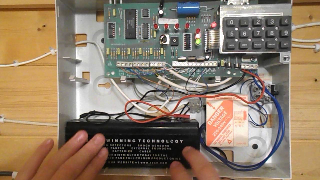
Power Wiring. A home alarm system is powered by a low-voltage transformer, which charges a 12-volt backup battery. The battery can usually run the system for a few hours in case of an electrical outage. Alarm system wiring from the transformer location to the main panel should be 4-conductor fire wire, 22-gauge minimum.
Contact Less Car Reverse Or Backup Alarm | Circuit Diagram
Free Wiring Diagram Acura Integra Wiring Diagram Listed below is the vehicle specific wiring diagram for your car alarm remote starter or keyless entry installation into your 1994 2001 acura integrathis information outlines the wires location color and polarity to help you identify the proper connection spots in the vehicle.

12v DC 8 Channel CCTV Camera Battery Backup UPS ...
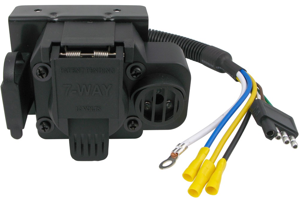
These backup alarm adapters provide an easily solution to alert bystanders of your vehicle reversing. They plug into your existing connector and still provide an outlet to hook up your trailer. * Available as 7-way flat to 7-way flat, 7-way flat to 6-round pin or 7-way flat to 4 & 5 flat all with an 80 decibel back-up alarm.
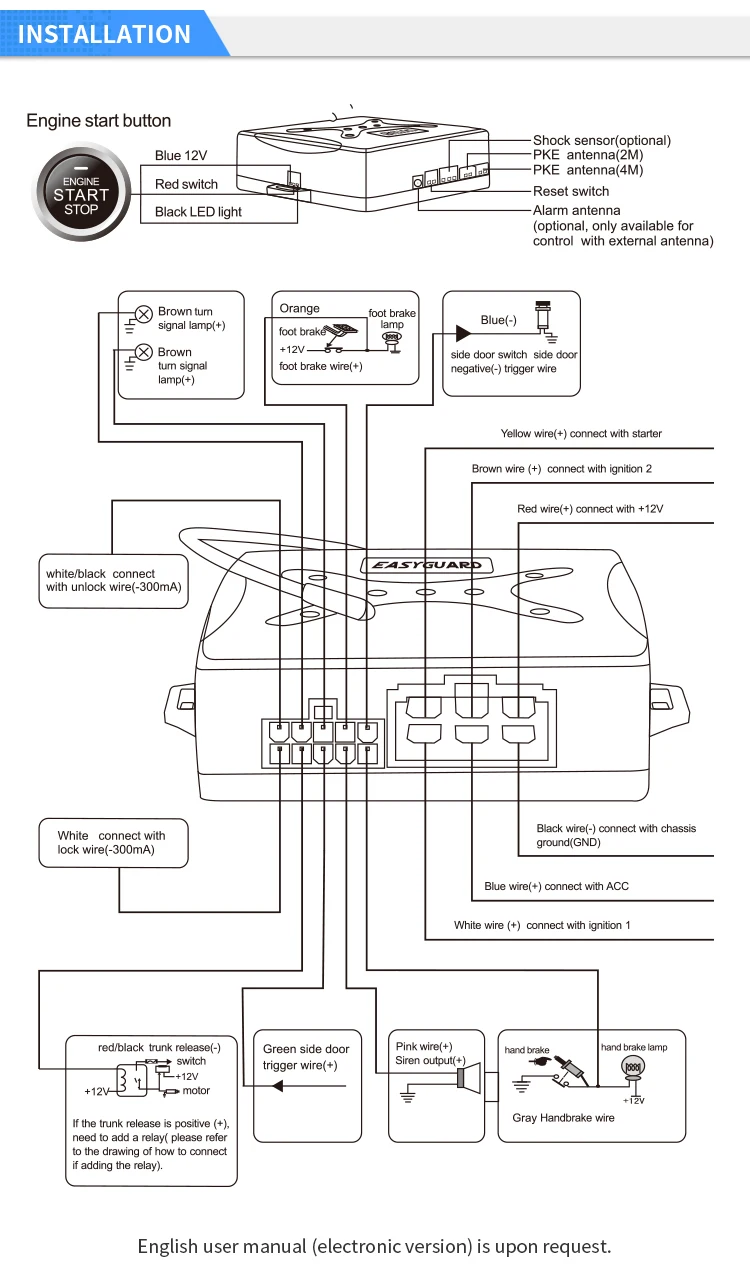
Car Finding Push Engine Start Remote Start Stop Pke Car ...
Dodge Ram ProMaster Alarm/Remote Start/Stereo Wiring - Can anyone provide me a alarm/ remote start wiring diagram for a Dodge Ram ProMaster? I . Looking for info concerning Ram Promaster Backup Light Wiring Diagram? you are right below. You might be a technician that wishes to look for referrals or resolve existing problems. Or you are a pupil ...

Honeywell Is2535 Motion Detector Wiring Diagram
Using wire nuts, attach the hot, neutral, and interconnect wires. Mount the alarm Next, you'll mount the alarm. 1. Thread the wires through the mounting bracket. 2. Secure the mounting bracket to the ceiling or wall using screws (included in packaging). 3. Insert the power connector into the plug on the back of your alarm. 4.
E-Z-Go Golf Cart Beeper and Picking Up Pruning Brush | Bob ...
Version. Listed below is the vehicle specific wiring diagram for your car alarm, remote starter or keyless entry installation into your 2004-2005 Dodge Ram . This information outlines the wires location, color and polarity to help you identify the proper connection spots in the vehicle. Please be sure to test all of your wires with a digital ...

Electrical Wiring Diagram Of 1962 Chevrolet 6 | All about ...
Central New York, USA. I'm attaching a wiring diagram for at lest one version of the 1845C. If your's has a pink wire coming from the harness going to the alarm + terminal there should be a black wire from the - terminal going to one of the two pressure switches and then on to the next switch and finally to a ground.

Adt Alarm System Transformer Wiring Diagram
Cat 246d Skid Steer Back Up Warning Wiring Diagram. INTRODUCTION The C/C/C/C Skid Steer Loaders, the the work tool directional spools, which control oil to the lift and tilt cylinders and the auxiliary circuit. Similarities and Differences The chart above shows the similarities and .. the backup alarm relay, the stop lamp relay, and the ride ...

2000 chevy express engine wont turn over when key is ...
Always check the latest information at the "Wiring Diagrams" location. Utilization of Body Builder connectors ordered and provided by Mack is strongly recommended as your power, lighting, and ground source for body installation, PTO installation, and operation. Cutting into wiring harnesses is not recommended as it may affect CAN Bus messaging.

Car Backup Alarm Circuit - Electronic Circuit
backup battery car alarm wiring diagram data diagram schematic backup battery car alarm wiring diagram data diagram schematic. A set of wiring diagrams may be required by the electrical inspection authority to agree to relationship of the habitat to the public electrical supply system.
Viper 5706 Install Pdf Elegant | Wiring Diagram Image
The orange wire should be hot from fuse 8. These two wires connect to the alarm. The lights aren't connected to the backup harness from Bobcat, but I suppose one could rig it up to work the lamps when in backup mode. The switches that activate the b-u alarm are under the cab.
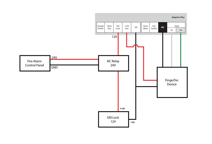
FingerTec Newsletter Vol: 12 Year: 2012 | FIRE ALARM SYSTEM
The backup alarm in a Yamaha golf cart is generally located behind the seat. ... Golf Cart Forward/Reverse Switch Wiring Diagram. The forward and reverse switch is popularly known as the F/R switch is located in the dashboard and is connected to several components. A solenoid, controller, and the reverse buzzer are some of the components ...
How to change the back-up battery in an optima xm burglar ...
Disclaimer: * All information on this site ( the12volt.com ) is provided "as is" without any warranty of any kind, either expressed or implied, including but not limited to fitness for a particular use. Any user assumes the entire risk as to the accuracy and use of this information. Please verify all wire colors and diagrams before applying any information.

Alarm Power Supply

Wiring Diagram Of Motorcycle Alarm System ...

Zoeller Sump Pump Wiring Diagram - Wiring Diagram Schemas

Wiring Diagram For Backup Alarm - FARAADIBA-FARAADIBA

Wiring Diagramfire Alarm Control Panel
Curt Trailer Connector Adapter with Backup Alarm - 4-Way ...
In-With-At-Wellreadmerhwellreadme-For-Code-Alarm-Best ...

Wiring Diagrams

Back-up Light Wiring Diagram | Auto Info | Pinterest ...
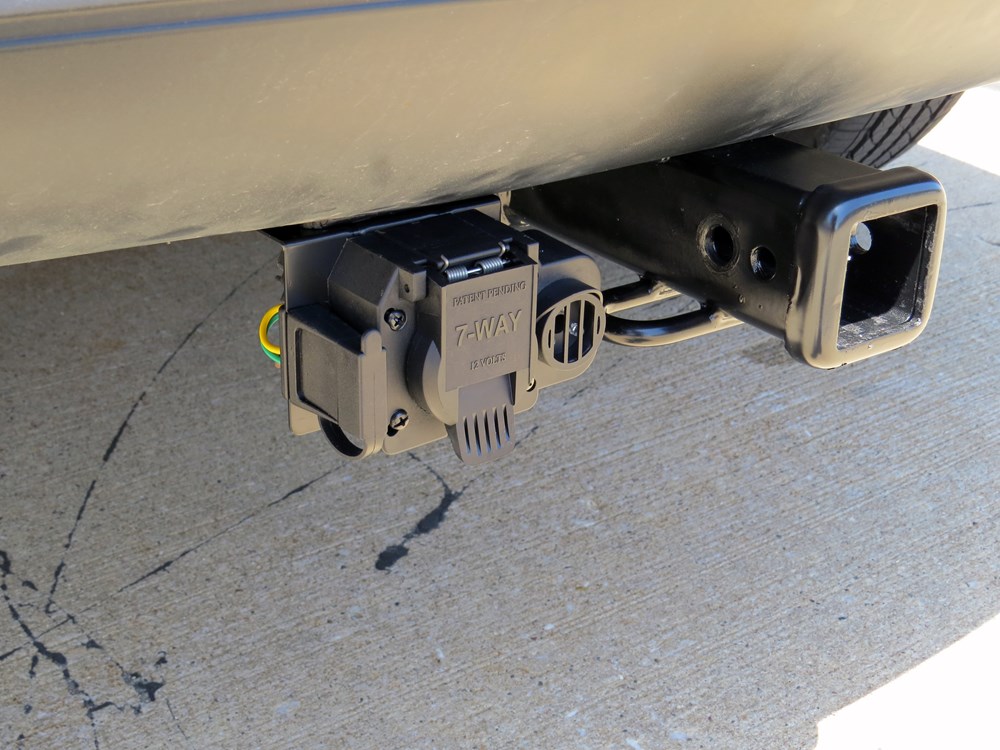
Curt Trailer Connector for Ford and GM Trucks - Backup ...

FORD NEW HOLLAND 250C 345C 455C 555C 655C OEM BACKUP ALARM ...

Silicon Chip Online - Circuit Notebook
2012 Toyota 4Runner Limited, alarm wiring

Wiring Diagram For Back Up Alarm - Complete Wiring Schemas
Hikvision Wiring Diagram

Honeywell Is2535 Motion Detector Wiring Diagram

Viper Responder 350 Wiring Diagram - Wiring Diagram

Wiring Diagram Flow Switch - Gambarin.us - Backup Gambar
Wiring Diagram For Back Up Alarm - Complete Wiring Schemas

Sump Pump Alarm Wiring Diagram - Wiring Schema
94 4runner astrostart guidance

2004 ford f250: backup alarm..bumper sensors..removing ...
Backup Alarm Wiring Diagram - CHEVABARNETT

Wiring Diagram For Back Up Alarm - Complete Wiring Schemas


Comments
Post a Comment