38 reversing motor starter wiring diagram
Wiring diagram single phase motor reversing switch wiring. Single phase motor starter connection. In this case, neutral white is carried through to the motor bypassing the starter altogether. Single phase motor starter switch connection. Motor 3ct to 120 v separate control * ot is a. Figure 1 is a typical wiring diagram for a three phase magnetic motor starter. Single phase magnetic starter wiring diagrams diagram base website wiring diagrams. It may also be wired for 120 volts. This flywheel is mounted on the engine crankshaft, so as the starter motor spins it turns the flywheel so as the crankshaft.
Nov 15, 2020 · Single Phase Reversing Motor Starter Wiring Diagram from www.practicalmachinist.com Print the wiring diagram off plus use highlighters to trace the signal. When you make use of your finger or perhaps the actual circuit with your eyes, it is easy to mistrace the circuit. 1 trick that We 2 to printing a similar wiring plan off twice.

Reversing motor starter wiring diagram
Oct 20, 2021 · Forward And Reverse Motor Starter Wiring Diagram Elec Eng World Electrical Circuit Diagram Electrical Wiring Diagram Electrical Diagram. A Wiring Diagram Of A Forward And Reverse Jogging Circuit Elec Eng World Diagram Jogging Wire. 3 Phase Forward Reverse Switch Wiring Diagram Earth Bondhon Reverse Delta Connection Switch. 2-Wire Control 6 3-Wire Control 6-9 Shunting Thermal Units During Starting Period 10 Overcurrent Protection for 3-Wire Control Circuits 11 AC Manual Starters and Manual Motor Starting Switches .....12 Class 2510 12 Class 2511 and 2512 13 2-Speed AC Manual Starters and Single phase reversing contactor wiring diagram. Why 3 phase ac instead of single phase. In the above one phase motor wiring i first connect a 2 pole circuit breaker and after that i connect the supply to motor starter and then i do cont actor coil wiring with normally close push button switch and normally open push button switch and in last i do connection between capacitor.
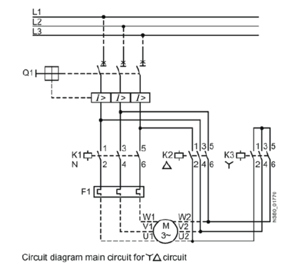
Reversing motor starter wiring diagram. 45 Unique Reversing Motor Starter Wiring Diagram Electrical Circuit Diagram Electrical Symbols Diagram . Pin On Hlektrologika . Forward Reverse Motor Control Diagram For 3 Phase Motor Electrical Online 4u Electrical Circuit Diagram Electrical Diagram Reverse . Use the wiring diagrams on the back of this sheet to install and connect power wires for the starter and motor. Connect power and ground leads from a fused disconnect or circuit breaker directly to the magnetic starter. Figure 1 is a typical wiring diagram for a three phase magnetic motor starter. It reveals the elements of the circuit as ... STAR-DELTA Starter Without Timer for 3 Phase induction motor. Power, Control & Wiring Diagram of Star-Delta Starter. R , Y, B = Red, Yellow, Blue ( 3 Phase Lines)C.B = General Circuit BreakerMain = Mai SupplyY = StarΔ = DeltaC1, C2, C3 = Contatcors (Power Diagram)O/L = Over Load RelayNO = Normally OpenNC = Normally Closed K1 = Contactor (Contactor coil) K1/NO = Contactor Holding Coil ... Square D Motor Starters Wiring Diagram - sq-d motor starter wiring diagram, square d 3 phase motor starter wiring diagram, square d 8536 motor starter wiring diagram, Every electric structure is composed of various distinct pieces. Each part should be placed and linked to different parts in specific way. If not, the structure won't work as it ought to be.
The motor draws more current, and it runs more efficiently at 220, 230 or 240 volts than 120 volts. Full-voltage non-reversing 3-phase motors. Star Delta Starter (YΔ) Starter Power, Control and If you have a 120V coil, instead of running a line from Coil - Overload - L2 , you must run Coil - Overload […] Sep 02, 2017 · Single Phase Forward Reverse Motor Wiring Diagram – – – Concer.biz, size: 800 x 600 px, source: concer.biz Here are a few of the leading drawings we obtain from various sources, we wish these pictures will serve to you, and with any luck very appropriate to just what you want about the Reversing Motor Starter Wiring Diagram is. Reversing Single Phase Motor Wiring Diagram - wiring diagram is a simplified enjoyable pictorial representation of an electrical circuit. It shows the components of the circuit as simplified shapes, and the power and signal connections amongst the devices. A wiring diagram usually gives counsel more or less the relative aim and settlement of ... To reverse rotation on a single phase capacitor start motor you will need to reverse the polarity of the starter winding. 120v Ac Capacitor Motor Reversing Switch Wiring Diagram. Not only will it help you achieve your desired. But for single phase AC motors the magnetic field only alternates back and forth.
A schematic diagram of a forward reverse control for a single phase split phase motor is shown in figure 2913. Single phase motor reverse and forward connection. Once the starting winding has been determined use the motors wiring diagram to determine which starting winding leads to swap. We use 2 magnetic contactors as forward reverse switch. Reversing an AC Motor. AC motor wiring diagrams are available for all of our induction motors, but we will explain how to reverse t he motor throughout the rest of this post. In order to reverse the direction of an AC motor, the magnetic fields must be altered to provoke movement in the opposite direction. Live. •. 3: Simplified GN0 Motor-Reversing SSR wiring diagram As can be seen from figure 3 above, two of the three phases are wired through the GN0 and the third phase is connected directly to the motor. When a logic signal is applied to the "forward" terminal, the GN0 switches L1 and L2 directly to . AQ18 Reversing Motor Control. Based on the wiring diagram shown, which of the following statements is true of a drum switch if the switch is placed in the reverse position? Based on the circuit diagram shown, what will happen to the motor if the JOG pushbutton is pressed? The motor will run until the JOG button is released. Nice work!
Wiring Diagram Forward-Reverse for 3 Phase Motor - My ...
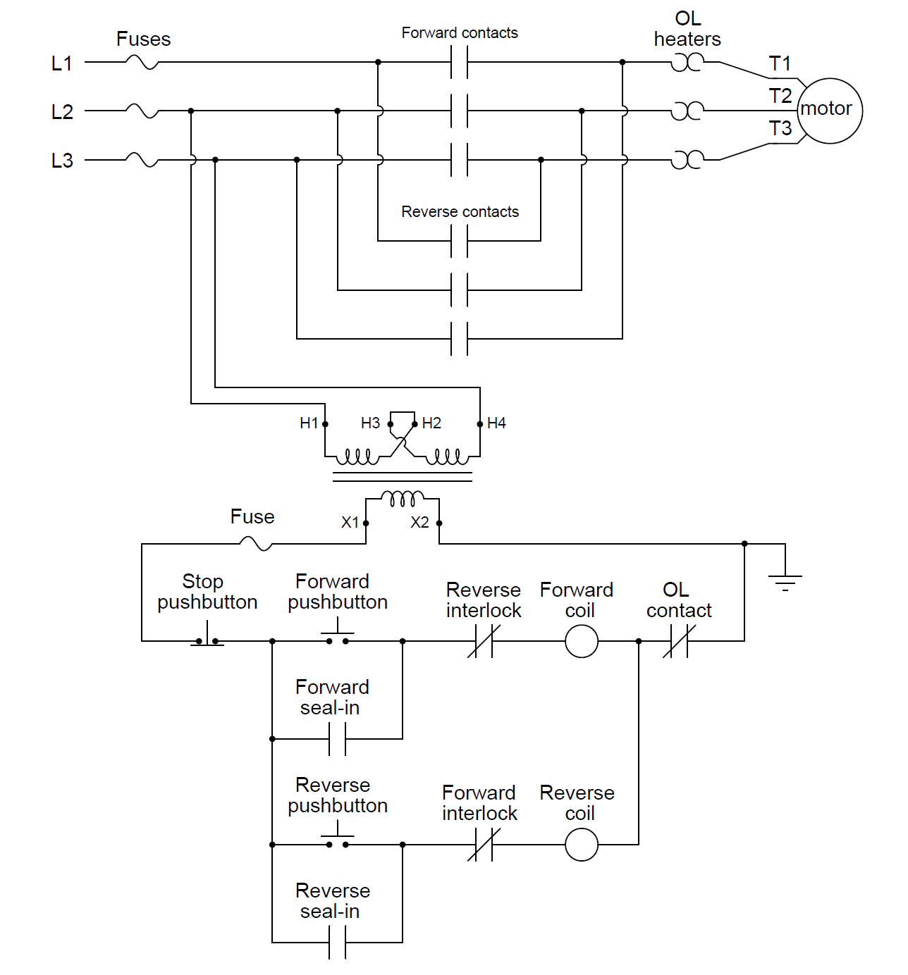
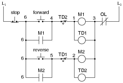
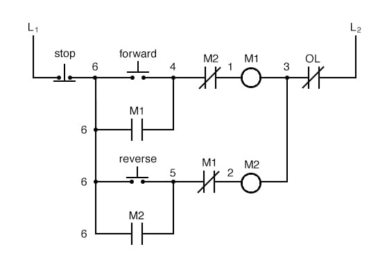
The circuit shown here provides two-direction control forward and reverse for a three-phase electric motor. Diagram wiring forward reverse starter learn 3 phase motor control using plc ladder dc circuit circuits logic auto star delta and applied the for pdf typical of direct switching single solved chapter 15 reversing motors electrical ...
Motor Control Circuit Wiring - Inst Tools
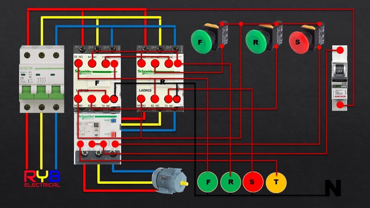
a) Full voltage non reversible 3 phase motors. b) Full voltage reversing 3 phase motors c) Single phase motors d) Wye-delta open transition We will show the basic circuit and in some cases pictures on how to connect the wiring. The pictures are shown here to teach the methods and are not intended to show how a panel is professionally wired.

Electrical and Electronics Engineering: Electrical Wiring ...
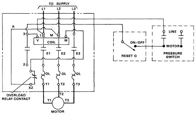
is a typical wiring diagram for a three-phase mag-netic starter. Figure 1. Typical Wiring Diagram Line diagrams show circuits of the operation of the controller. Line diagrams, also called "schematic" or "elementary" dia-grams, show the circuits which form the basic operation of the controller. They do not indicate the physical relation-
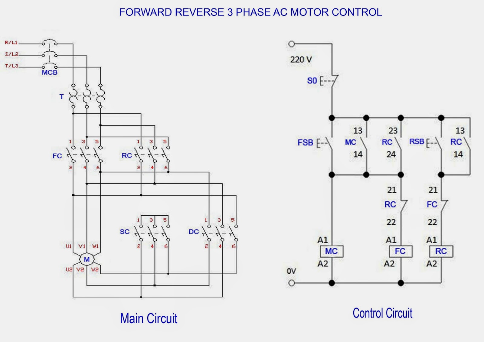
Forward Reverse 3 Phase AC Motor Control Wiring Diagram – Mr ...
Reversing Magnetic Starters. If a motor is to be driven in two directions, then it will require a Forward / Reverse motor starter, which has two three-pole horsepower-rated contactors rather than just one as in the conventional starter. Each of the two different motor starters powers the motor with a different phase rotation.
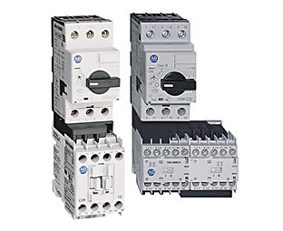
IEC Open Starters | Allen-Bradley Indonesia
A wiring diagram is a simplified conventional pictorial representation of an electrical circuit. Or how make a forward reverse 3 phase motor starter. Variety of single phase motor wiring diagram forward reverse. Forward reverse three phase motor wiring diagram electrical info pics.

Sequence Controls for Motor Starters
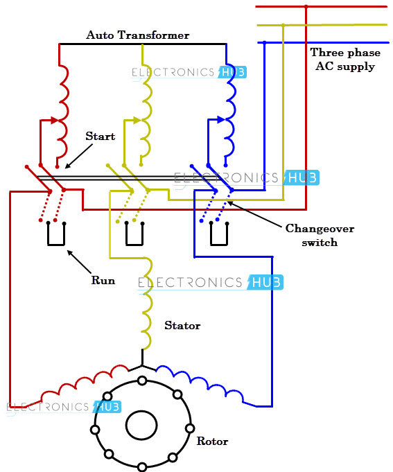
A star delta starter is the most commonly used method for the starting of a 3 phase induction motor.in star delta starting an induction motor is connected in through a star connection throughout the starting period. Forward and reverse motor starter wiring diagram elec eng world electrical circuit diagram circuit diagram electrical diagram.

The most used 3 Basic Motor Starter with it's PLC Program!
This wiring should not be used on 240 volt circuits. 240 volt, 1 phase motors should use a 2 pole starter. L1 is Line 1 in and should be connected to one of the "hot" wires, L2 is Line 2 in and should be connected to the other "hot" wire. T1 and T2 are the corresponding motor out connections and should be carried through to the motor.

Diagram of 3-Phase Reversing Motor Control with 24 VDC ...
WIRING DIAGRAMS w Bulletin 609RS & 609TS The Bulletin 609RS manual reversing starters and the Bulletin 609TS manual two-speed starters consist of two standard Bulletin 609 starters mounted in a single enclosure. Internal wiring of these starters provides the necessary connections for interchanging two motor
Reverse Forward DOL Starter Power and control Wiring
Single Phase Motor Wiring Diagram Forward Reverse - single phase induction motor forward reverse wiring diagram, single phase motor forward reverse wiring diagram pdf, single phase motor wiring diagram forward reverse, Every electrical arrangement consists of various unique components. Each part ought to be set and connected with different parts in specific manner.

Star Delta Forward Reverse Starter with PLC Ladder Logic ...
3 phase motor starter wiring diagram pdf source. A wiring diagram is a streamlined conventional photographic representation of an electrical circuit. Ac manual starters and manual motor starting switches 12 class 2510 12 class 2511 and 2512 13 2 speed ac manual starters and. Phase 2 l1 l2 l3. They can be used as a guide when wiring the controller.

Star Delta Forward Reverse Starter with PLC Ladder Logic ...
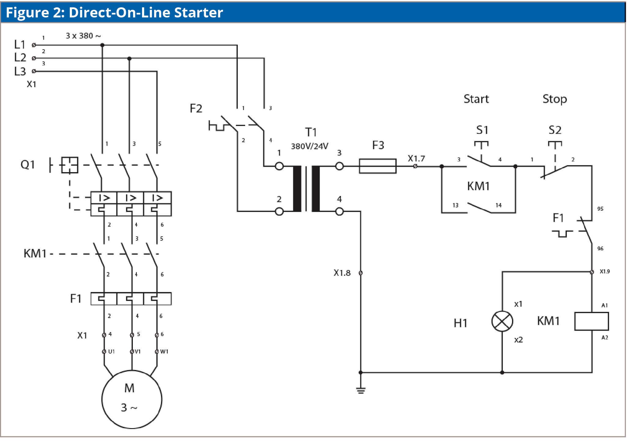
A motor starter is a combination of devices used to start, run, and stop an AC induction motor based on commands from an operator or a controller. In North America, an induction motor will typically operate at 230V or 460V, 3-phase, 60 Hz and has a control voltage of 115 VAC or 24 VDC. Several other combinations are possible in North America and other countries and are easily derived from the ...

3 phase switch galagif.com
Single phase reversing contactor wiring diagram. Why 3 phase ac instead of single phase. In the above one phase motor wiring i first connect a 2 pole circuit breaker and after that i connect the supply to motor starter and then i do cont actor coil wiring with normally close push button switch and normally open push button switch and in last i do connection between capacitor.
What are the functions of KM1 and KM3 in the ATS48 soft ...
2-Wire Control 6 3-Wire Control 6-9 Shunting Thermal Units During Starting Period 10 Overcurrent Protection for 3-Wire Control Circuits 11 AC Manual Starters and Manual Motor Starting Switches .....12 Class 2510 12 Class 2511 and 2512 13 2-Speed AC Manual Starters and
Motor Starter Wiring Diagram
Oct 20, 2021 · Forward And Reverse Motor Starter Wiring Diagram Elec Eng World Electrical Circuit Diagram Electrical Wiring Diagram Electrical Diagram. A Wiring Diagram Of A Forward And Reverse Jogging Circuit Elec Eng World Diagram Jogging Wire. 3 Phase Forward Reverse Switch Wiring Diagram Earth Bondhon Reverse Delta Connection Switch.
Star Delta Starters Explained - The Engineering Mindset
How do I connect a direct on line (DOL) starter to a single ...

Motor Control Circuit Forward Reverse | Wiring and Connection ...
PLC Implementation Of Forward/Reverse Motor Circuit With ...

Reverse Motor Starters
MOTOR CIRCUITS AND CONTROL – Applied Industrial Electricity
Motor Control Circuits | Ladder Logic | Electronics Textbook

Forward Reverse Starter With Timer 3 Phase Motor Wiring Diagram

Interlocking Methods for Reversing Control (Basic Control ...

Motor Starter Explained | Motor Starter Types

Forward-Reverse Control

Magnetic Motor Starter Basics | EC&M

Forward Reverse Starter Diagram - Learn Electrician

Motor Starter Wiring Diagrams - VintageMachinery.org ...

Electrical Installation - Basic Vocational Knowledge: 7 ...
How can we switch a single-phase motor forward, reverse, and ...
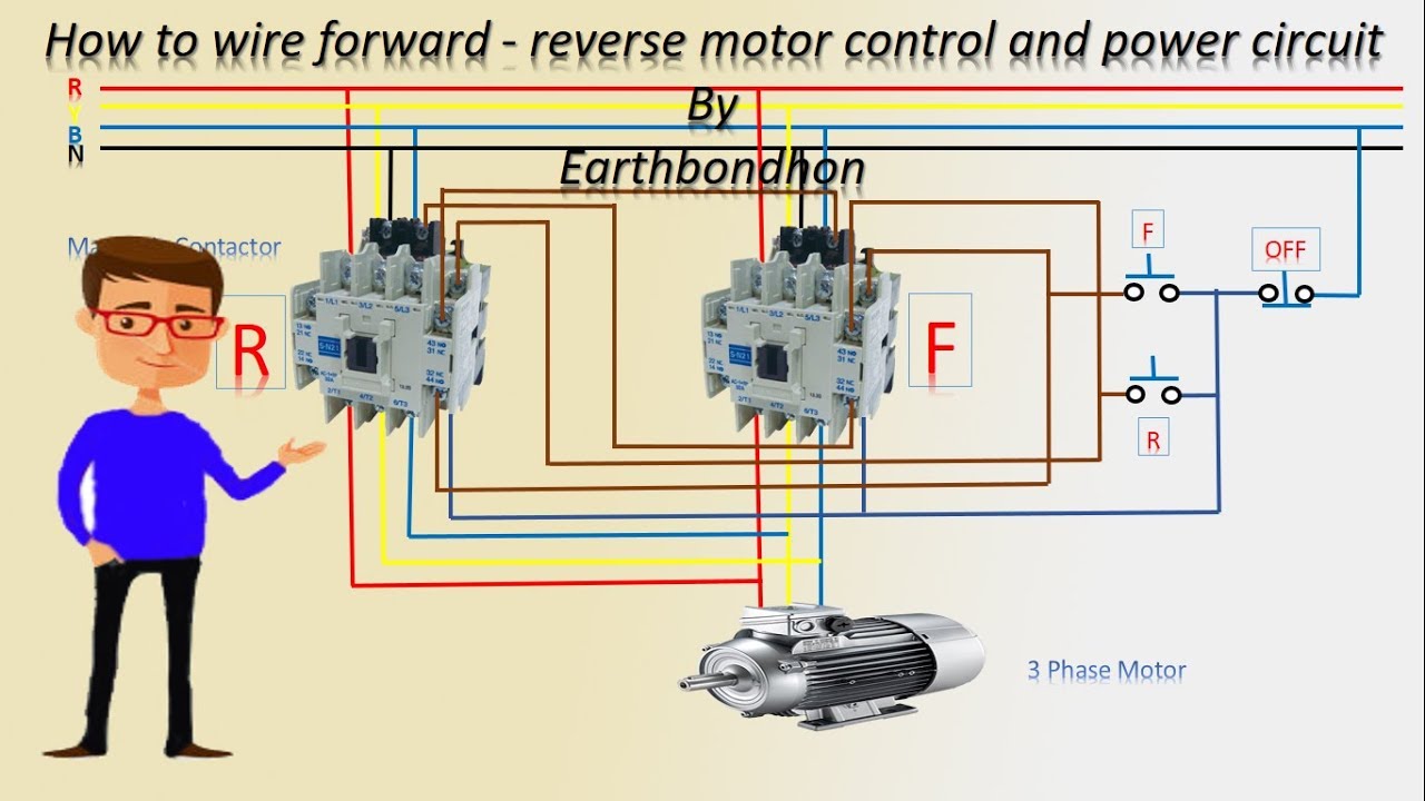
How to wire forward reverse motor control | 3 Phase motor | Earthbondhon

Motor Starter Explained | Motor Starter Types - RealPars

Motor Control Circuit Wiring - Inst Tools

Motor Control Circuit Wiring - Inst Tools

Direct Online Starter | DOL Starter, working,principle ...
Industrial Motor Control Starters | Magnetic Motor Starter ...
What is Motor Starter

4. Electrical Machines


Comments
Post a Comment