38 two pipe steam system diagram
In this excerpt from his Dead Men's Steam School seminar, Dan Holohan looks at all of the different types of piping that you will find on steam heating syste... Example 10.2.2. Consider the system shown in Figure 10.2.6, and determine the pipe size required from the boiler to the unit heater branch line. Unit heater steam load = 270 kg/h. Although the unit heater only requires 270 kg/h, the boiler has to supply more than this due to heat losses from the pipe. The allowance for pipe fittings
Figure 4.1 is an example of a very simple block diagram. Two feed streams enter the unit. Each is purified; they are then mixed with one another and sent to the reaction section. The material leaving the reaction section—a mixture of product and unreacted feed materials—goes to a separation unit. Product is sent to purification; unreacted feed returns to the reaction section.

Two pipe steam system diagram
Jan 01, 2022 · Therefore, opening a steam valve and allowing steam to be released into the atmosphere provides a visual manner of estimating the steam quality in the system. To learn more about steam valves, read Proper Sizing and Installation for Steam System Safety Valves, Chem. Eng., July 2017, pp. 48–51. U = 2-row Chilled Water/Hot Water, 2-pipe D = 3-row Chilled Water/Hot Water, 2-pipe E = 4-row Chilled Water/Hot Water, 2-pipe F = 5-row Chilled Water/Hot Water 2-pipe G = Direct Expansion (DX) S = 3-row Chilled Water V = 2-row Chilled Water W = 4-row Chilled Water Y = 5-row Chilled Water 7. Heating Options 00 = None steam in the system condenses. This allows all the vents and vacuum breakers to re-open and let the air back into the system. (This includes the radiators and the piping.) This one detail is critical for the system to operate properly. When the boiler fires back up for the next heating cycle, the steam will push the air out of
Two pipe steam system diagram. Look at this sketch, here a red & blue arrow shows that mass & energy respectively can transfer to the system and from the system. CS is a control surface that separates control volume from the surrounding. In case of a closed system, we all know that no mass transfer from or to the system but energy transfer can happen. a) The lowest steam carrying pipe must be at least 28 inches above the normal boiler water line. B. SYSTEM CHECKLIST 1. The system piping must provide dry steam—wet steam causes water hammer, component damage and water level problems. 2. Make sure air vents are working. a) The most important vents are the main and riser vents. The Steam System Modeling Tool (SSMT) ... –Determines steam and liquid water properties given two properties that fix the state Both calculators include: ... steam properties for a steam pipe or header based on specific given inlet steam conditions and a % heat loss. A general rule of thumb is that 1 psi of steam will raise water about 2 feet. For example, a 5 psi system should not have condensate lines higher than 10 feet above the steam trap. Properly Size Steam Trap Drip Leg Lines. Not only must steam traps be piped off the bottom of the steam lines, the pipe must be properly sized.
Steam Boiler Diagram With Parts for Dummy's. Below is a typical steam boiler diagram for dummy's to understand with name of each component or boiler part. First of all you should understand that there are many types and nomenclature of boilers. For example steam boiler, combi boiler, vaillant boiler, hot water boiler, gas boiler, electric ... When steam includes these tiny droplets, it is called wet steam. In a steam system, steam released from steam traps is often misinterpreted to be saturated (live) steam, while it is in fact flash steam. The difference between the two is that saturated steam is invisible immediately at the outlet of the pipe whereas flash steam contains visible ... Read an introduction to two-pipe steam systems here. One-pipe steam radiator components. The inlet, or control, valve must have a large internal bore: minimum of 1" for radiators of 5000 BTUs or fewer; at least 1-¼" above that. On a one-pipe steam radiator it must be fully open or fully closed. Installation and maintenance of the steam system are important issues, and must be considered at the design stage. Figure 3.2 Steam Distribution System As steam condenses in a process, flow is induced in the supply pipe. Condensate has a very small volume compared to the steam, and this causes a pressure drop, which causes the steam
Another solution to loss of brake pressure is the two-pipe system, fitted on most locomotive-hauled passenger stock and many freight wagons. In addition to the traditional brake pipe, this enhancement adds the main reservoir pipe, which is continuously charged with air directly from the locomotive's main reservoir. The main reservoir is where the locomotive's air compressor … An old steam system can be plenty dirty, and since steam is moving at high velocity (up to 60 mph in a one-pipe system!), it picks up particles of rust and sediment. Eventually, this stuff winds up inside the main vent. Before long, your main vents won't shut. They'll spit water and let steam pass to the atmosphere. Steam Coil Vacuum Breaker Airflow Condensate Return Main Trap 12" Min. 2 4 Air Vent 3 5 Condensate Return Safety Drain Vacuum Breaker 6 12" Min. 1 7 7 12" Min. C-14 Recommended Piping Practices for Steam Heating Coils 1. 24" minimum if safety drain is used. 2. Safety drain is used if steam supply is modulated and the condensate system is ... I've seen that same problem with start up on large single zone two pipe systems with our outdoor reset mod steam boilers with the system converted to supply valve orifices. However, we've found so far that running only 1/3 to 1/2 of the orificed radiator capacity is all that is needed to get the system moving.
Class 108 No. L231 stabled at Cranmore, East Somerset Railway.
An optimized two-pipe steam system retrofitted with orifice plates, thermostatic radiator valves (TRVs), and properly sized vents provides efficient and balanced heat. air vent TRV steam water. nyc.gov/RetrofitAccelerator Tech Primer: Two-Pipe Steam Optimization AN 2019 V1 3
PIPE SYSTEMS1
When steam condenses, its volume is dramatically reduced, which results in a localised reduction in pressure. This pressure drop through the system creates the flow of steam through the pipes. The steam generated in the boiler must be conveyed through the pipework to the point where its heat energy is required.

Screen Shot 2021-03-18 at 2.22.36 PM
Figure 1 A typical flash tank piping diagram discharging to atmosphere. NOTE: Omit trap if condensate is discharged into vented pump receiver. Figure 2 A typical flash tank piping diagram with flash discharging to low-pressure steam system. Figure 3 This diagram depicts a combination flash tank installation with subcooling condensate. VENT ...

Monochrome, Dounreay Nuclear Establishments, Caithness, Highlands, Scotland.
Oct 17, 2019 · Pipe wall thickness calculation is very important in any material specification, and crucial to identify required schedule of any pipe, fittings, and flanges as per process requirements. Same has been already derived in ASME B 31.3. This blog post simplifies the calculation stepwise, to comprehend and determine pipe wall thickness.

Water Fall
Two staged systems and boosters. A system is said to be in a two staged set up if two separate gas compressors in serial display work together to produce the compression. A normal booster installation is a two staged system that receives fluid that cools down the discharge of the first compressor, before arriving to the second compressor's input.

whoosh
Figure 2 illustrates the steps in a boiler firing cycle without main line valves. At the beginning of a boiler firing cycle, the piping system and radiators are filled with air, which appears white in diagram A. Diagram B illustrates the system as steam heats the large mass of piping and pushes air out of the line toward the radiators.

Screen Shot 2021-03-18 at 2.22.18 PM
This length of pipe (4.7 m) is probably impractical in the field. Two alternatives remain. One is to increase the diameter of the drain line, which is still usually impractical; the other is much simpler, to fit the correct trap for this type of application; a float-thermostatic trap which discharges condensate at steam temperature and hence requires no cooling leg.

Espresso with latte art
1-Pipe Steam System. A 1″ NPT tapping is included on each corner of the radiator. Two 1″ plugs are provided to plug the two unused radiator tappings. Use a 5/8″ allen wrench to tighten these plugs. A third plug with a 1/8″ vent tapping is also included. Pipe dope should be applied to the plugs.

One Pipe System , Two Pipe System dan Single Stack System ...
1. Piping systems designed for steam pressure below 25 psig are low-pressure steam systems. Piping systems designed for steam pressures from 25 psig up to and including 125 psig are medium-pressure steam. Systems 126 psig and above are high-pressure steam. 2. Distribution piping complying with Thermal Energy Cooperative (TECO) requirements is

Screen Shot 2021-03-18 at 2.23.36 PM
The primary component of a Hartford loop diagram is the location of a Hartford loop top and its distance from the boiler water top. Standard Hartford loop diagrams generally place the top of the loop 2 inches below the steam boiler's water line. hartford loop steam piping diagram is among the photos we discovered on the net from reputable sources.

Screen Shot 2021-03-18 at 2.27.57 PM
Steam lines should ideally be arranged to fall in the direction of flow, at not less than 100 mm per 10 m of pipe (1:100).This slope will ensure that gravity (and the flow of steam), will assist in moving the condensate towards drain points so that the condensate may be safely and effectively removed (see Fig. 15.4).Any steam lines rising in the direction of flow should slope at not less than ...

Screen Shot 2021-03-18 at 2.21.59 PM
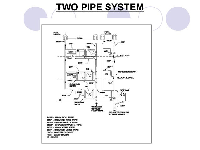
The condensate pipe is smaller than the steam pipe because it carries a liquid. In a two pipe system, the steam is kept separate from the condensate. In a one pipe system, the steam and condensate shared the same pipe. The two pipe system can be converted to a hot water system. The one pipe system cannot, without expensive re-piping. In a two ...

Beautiful boundless planet/Fangruida
In two-pipe systems, older steam traps often stick in either the open or closed position, causing unbalance in the distribution system. If you seem to have problems with some radiators providing too much heat and others providing too little, this might be the cause.

Andromeda galaxy
The two pipe reverse return configuration which is sometimes called 'the three pipe system' is different to the two pipe system in the way water returns to the boiler. In a two pipe system once the water has left the first radiator it returns to the boiler to be reheated, and so with the second and third etc.
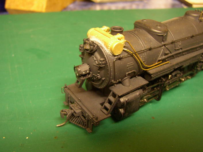
Mantua 2-8-2 rebuild - Model Railroader Magazine - Model ...
Single Pipe Central Heating System A single pipe central heating system operates through a main single feed hot water supply pipe which comes from the boiler supplying hot water to each radiator. Each radiator has a smaller hot water supply pipe branched off the main feed pipe to supply the radiator, the water passes through the radiator coming out the other side a little cooler and then mixed ...

Screen Shot 2021-03-18 at 2.26.09 PM
Single Pipe Steam System with Main Pipes Pitched Towards the Boiler. Steam and condensate use the same main pipes. The condensate flows in the opposite direction of the steam. Air valves are necessary for evacuating air during start-up. The system is simple but the heat emission from radiators or in heat exchangers is hard to control.
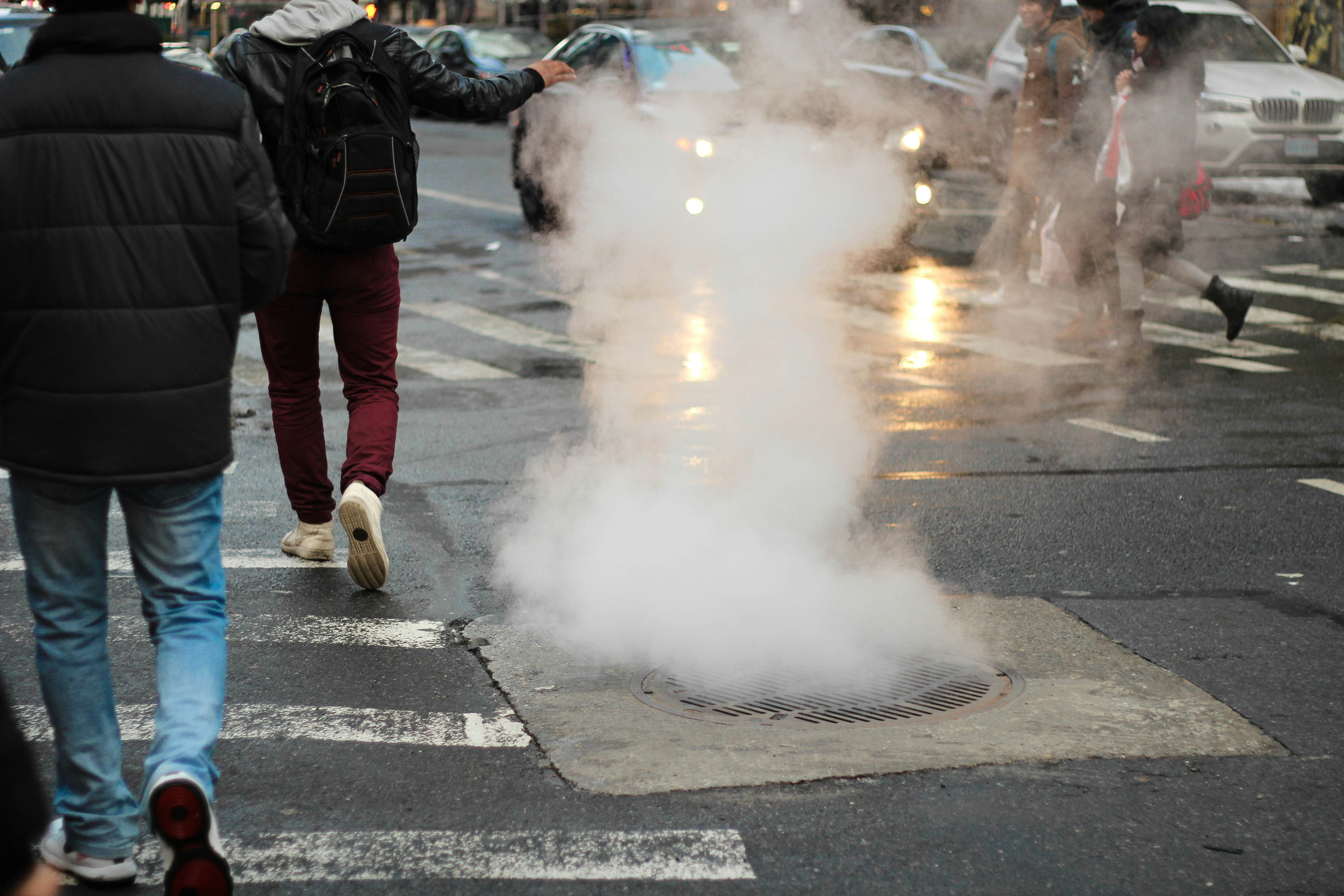
Crosswalk Smoke
The attached diagram is what I mean by a one pipe system. The main pipe is copper and is 1.5". The other side has a shut off valve see photo. The system works great and I don't want to mess with it just need to take the radiator out while I remodel the bathroom, and then put it back in when I'm done.

water level to high - DoItYourself.com Community Forums
A 2-pipe HVAC system is one that uses the same piping alternately for hot water heating and chilled water cooling, as opposed to a 4-pipe system that uses separate lines for hot and chilled water. Two-pipe originated 50 or 60 years ago as a cost-effective way to add air conditioning.

THE FLOOD OF 1771 IN RICHMOND (RVA)
Process flow diagram for the double-pipe heat exchanger ... cause problems in system oper ation. Two prob lems that can interfere ... This valve allows steam to …

20-260 Class 108 No. L231 stabled at Cranmore
Fundamentals Of Two-Pipe Steam Radiators. In two-pipe steam installations, steam flows from the boiler to the radiators through an inlet pipe. Once the steam condenses it returns to the boiler through a second outlet pipe. You can typically recognise a two-pipe system from the two pipes and lack of steam vent attached to the radiator.

The entrance of Two Exchange Square in Central District of Hong Kong, with the HKEX headquarter located there. The outdoor LED display screens also display information about the HKEX. The sculpture 'Oval with Points' designed by Henry Spencer Moore is located in the circular foundation in front of the entrance.
heater. The steam and water mixture enters the steam drum through riser tubes, drum internals consisting of demister separate the water droplets from the steam producing dry steam. The saturated water at the bottom of the steam drum flows down through the down comer pipe, normally unheated, to headers and water drum.

Dublin vales
steam in the system condenses. This allows all the vents and vacuum breakers to re-open and let the air back into the system. (This includes the radiators and the piping.) This one detail is critical for the system to operate properly. When the boiler fires back up for the next heating cycle, the steam will push the air out of

MN tones.
U = 2-row Chilled Water/Hot Water, 2-pipe D = 3-row Chilled Water/Hot Water, 2-pipe E = 4-row Chilled Water/Hot Water, 2-pipe F = 5-row Chilled Water/Hot Water 2-pipe G = Direct Expansion (DX) S = 3-row Chilled Water V = 2-row Chilled Water W = 4-row Chilled Water Y = 5-row Chilled Water 7. Heating Options 00 = None

Cycle Times - Help? — Heating Help: The Wall
Jan 01, 2022 · Therefore, opening a steam valve and allowing steam to be released into the atmosphere provides a visual manner of estimating the steam quality in the system. To learn more about steam valves, read Proper Sizing and Installation for Steam System Safety Valves, Chem. Eng., July 2017, pp. 48–51.

Screen Shot 2021-03-18 at 2.11.28 PM

Screen Shot 2021-03-18 at 2.25.30 PM

Screen Shot 2021-03-18 at 2.10.13 PM
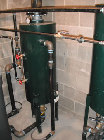
Boiler Installations in Craft Breweries / Microbreweries ...

Unexplored at Gooseberry Falls

Jupiter and Saturn conjunction with Jupiter moons.

While I was away on a weeks holiday to Portugal, I decided to take a chance on seeing where the Milky Way and the Moon would be showing in relation to my location. To my surprise, the Moon was always below the horizon when the Milky Way was up. This was my first proper time photographing the Milky Way and I was seriously lucky to have really good conditions to capture it in. Would make a good phone background :)

1894 U.S.C.&G.S. MAP, RICHMOND, VIRGINIA

Hydronic Heating System

This is a photo of me and my dad, taken by my mum in 1975 on a Halina 35mm camera that she bought in 1968

Screen Shot 2021-03-18 at 2.21.13 PM

Image from page 429 of "The American florist : a weekly journal for the trade" (1885)

Ministry Of Defence, Vulcan Naval Reactor Test Establishment, Caithness, Highlands, Scotland.

Screen Shot 2021-03-18 at 2.24.42 PM


Comments
Post a Comment