39 electric fence circuit diagram
4: Electric Fence Energizer Block Diagram. Electric fence 20KV - YouTube Here is an electric fence, perimeter protection circuit, designed to run on batteries, and provide configurable pulses of up to 20KV, to protect a tent perimeter could you please give out the schematic diagram of this? An electric fence circuit is made on a larger scale. It consists of guidelines and diagrams for different types of wiring strategies and other items like lights Electric fence wire diagram wiring diagram database architectural wiring diagrams sham the approximate locations and interconnections of...
Most of the tutorials I see for AutoCAD are always involving complicated motors and such. I was just wondering where to begin when making a really simple circuit diagram with just a battery and a few resistors in AutoCAD. Something like these: [https://imgur.com/a/TzCn4YD](https://imgur.com/a/TzCn4YD) Thanks

Electric fence circuit diagram
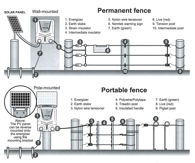
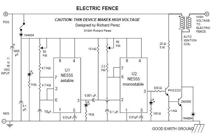
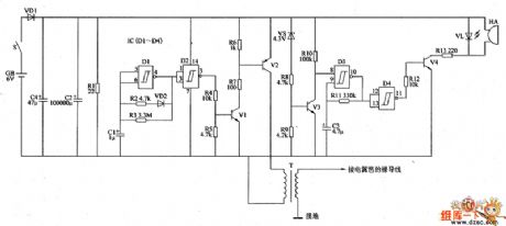
The electric fence charger circuit presented here is basically a high voltage pulse generator. The super high voltage is derived from a commonly used automobile ignition coil. An astable multivibrator is used to generate the required frequency to drive the ignition coil. This is a Electric Fences Circuit Diagram for rural electrification of about fed with just one 9-volt battery, the circuit is small, so it is portable and handy, its operation is based on NE555 integrated circuit which generates pulses with the same time intervals set by resistor R2 together with P1 default... Details: electric fence wire diagram wiring diagram database. Architectural wiring diagrams sham the approximate locations and interconnections of Details: 11+ Electric Fence Circuit Diagram. The solar panel collects the energy from the sun and charges. Each is described in detail in the output side...
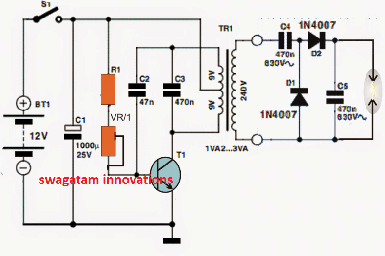
Electric fence circuit diagram. Sep 29, 2015 · Astable mode works as a oscillator circuit, in which output oscillate at a particular frequency and generate pulses in rectangular wave form. Using 555 timer IC, we can generate precise time duration of HIGH and LOW output, from micro seconds to hours, that’s why 555 is very popular and versatile IC. Mar 06, 2019 · The diagram offers visual representation of the electric structure. However, the diagram is a simplified version of this arrangement. This makes the procedure for building circuit easier. This diagram provides information of circuit components in addition to their own placements. Components of Kenworth W900 Wiring Diagram and A Few Tips The circuit of a simple electric window charger. With a couple of minor circuit variations, it can be used as an electric fence charger too. A standard 12V, 7Ah sealed maintenance-free (SMF) UPS battery is required for powering the entire unit. Hello everyone, I am working on a project ,where I need to create electrical circuit diagrams. I have found schemdraw package for producing electrical circuit diagrams. But is there any other way to create electrical circuit diagrams?
Windowfence charger circuit diagram electric fence energizer v best idea garden fence wiring schematic marvelous for perimeter protection u pocketmagic reverse engineering an steps (with great for component circuits diagrams control a charger or energizer is equipment which used arduino. Diagram Electric Fence Circuit Diagram Full Version Hd Quality Circuit Diagram Diagramworkb Portaimprese It. Electric Fence Energizer Block Diagram Download Scientific Diagram. Electric Fence Circuit For Perimeter Protection Pocketmagic. Nov 08, 2020 · A wiring diagram is a simple aesthetic depiction of the physical links as well as physical layout of an electric system or circuit. It demonstrates how the electrical cords are adjoined and could also reveal where fixtures and components may be attached to the system. The electric circuit diagram includes the adhering to signs. The fence wires are powered by govt norms of safity the rds brings nemtek merlin stealth m25s, m28s is a powerful range of energizers, that can be used as simple high end. Electric fence grounding is one of the most important aspects of...
Surf Simulator Circuit Diagram When The Siren Sounds - A Useful Circuit Simple White Noise Generator Balanced-Unbalanced Converter For Audio Work Automatic Loudness Control Cuckoo Sound Generator Cricket Chirping Generator Bells Ring Generator Melody Generator 4 Channel Portable Audio Mixer Music Generator Schematic Using UM66 Laptop Audio-Out ... Hey all i have an in class assignment due next thursday to make a ladder diagram of each circuit in shop ( wouldnt be posting here if i havent already exhausted every other method of learning them ) i have pictures and diagrams to those who are willing to help the one i am currently attempting is a single phase 120 volt with dual pressure control, oil safety control, box temp stat, defrost timer, and a fan defrost control. I have an already attempted mock up if it will help as well Thanks in ad... Wizard 4 Electric Fence Energizer Wiring Diagram. Electric Fence U2013 20kv Pulses For Perimeter Defense. Electric Fence Control Circuit 2 Under Repository. Electric Fence Circuit For Perimeter Protection U2013 Pocketmagic. Does My Electric Fence Need To Be A Circuit. Electrical engineering news, resources, electronic design projects, circuit diagrams and diy projects with schematic for students and hobbyist. Wiring diagram electric fence valid invisible fence wiring diagram. Take time to properly connect lead out wire, ground wire and fence line...

SOLAR ELECTRIC FENCE - Silver Solutions Limited
Electric fence energizer circuit diagram integrated system. A first appearance at a circuit representation could be confusing, however if you could review a train map, you could check out schematics. A newbie s overview to circuit diagrams.

Quality Replacement Parts | Cyclops Electric Fence ...
Electric fence electric fence controller circuit. Electric fence wire diagram wiring diagram database. It won't damage the circuit if that happens, but it The electric circuit diagram includes the adhering to signs. The electric fence charger circuit presented here is basically a high voltage pulse generator.

Wiring Diagram For Electric Fence : The grounding circuit ...
Electric Fence Circuit Diagram - The Wiring Diagram ... from lh5.googleusercontent.com. If you have a large pasture on which your cattle graze, you must Here is the circuit of a simple electric window charger. Windowfence charger circuit diagram electric fence energizer v best idea garden fence...

Gallery Of Invisible Fence Wiring Diagram Sample
Electric fence energizer simple circuit circuit design circuit diagram wire fence fence design image house coast technology. An electric fence is an 1 hours ago electric fence circuit diagram Do you mean by the fence to keep people away. Charge a capacitor to A.C mains voltage through a very high...
Nemtek Agri 5km Solar Electric Fence Energizer [NMT025 ...
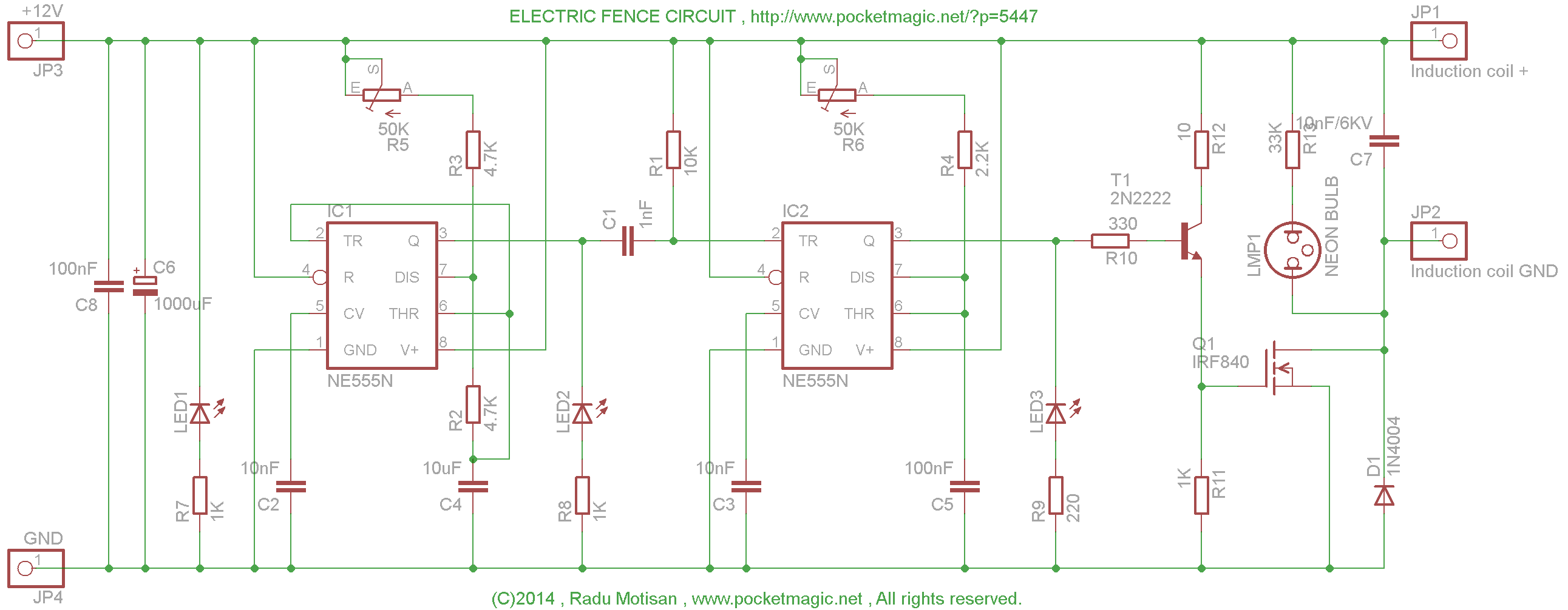
Here is an electric fence perimeter protection circuit designed to run on batteries and provide configurable pulses of up to 20KV, to protect a tent perimeter against bears or other animals, out in the wild. It doesn't kill as the output current is limited, but it is definitely not for those with medical (heart)...
How To Wire An Electric Fence Diagram Beautiful Electric ...
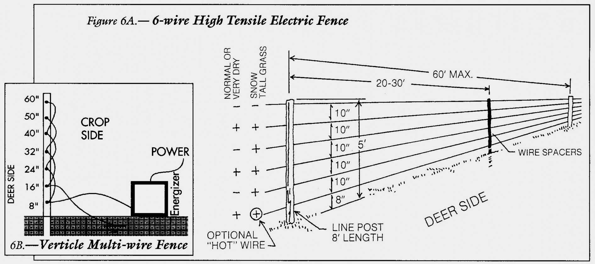
Electric fencing basics gallagher electric fence usa. Residential electric wiring diagrams are an important tool for installing and testing home electrical circuits and they will also help you understand how electrical devices are wired and how various electrical devices and controls operate.

Circuit Diagram Electric Fence Energizer
I am trying to make a magic system which relies on magic circles, magic language, grimoires, geometry, etc... for a game. So I want to be a bit puzzle-like, easily understandable yet quite versatile. My idea was to make them like Electronic Circuits, with a magic source representing a battery or an AC source, some parafernalia in the middle that transforms magic energy into other types of energy(maybe elemental magics since I want my system to be elemental) then ground it. Since Electron...

electric fence schematic
Sep 20, 2017 · Resistance, small bundle of resistance, is one of the most commonly used primary components in the electric circuit. The most frequently used to streamline current flow by adding / reducing resistance from the circuit, these resistors are available in many forms and sizes.
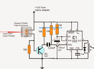
Laser Alarm Circuit for Protecting Field Crops against ...
Windowfence charger circuit diagram electric fence energizer v best idea garden fence wiring schematic marvelous for perimeter protection u pocketmagic reverse engineering an steps (with great for component circuits diagrams control a charger or energizer is equipment which used arduino.

Electric Fence Circuit Diagram 12v: Electric Window/Fence ...
DIY Electric Fence Circuit. Смотреть позже. Поделиться.
What is an electric fence energizer with a circuit diagram ...
Circuit Diagram Electric Fence Using Car Coil Car Wiring Diagrams. Electronic Circuit Diagrams / Circuit Schematics. Electronic circuit schematics - satsleuth. Asian carp have been found in the Illinois River, which connects the Mississippi River to Lake Michigan.

Ignition coil driver schematic | Gadgets in 2019 ...
Simple electric fence circuit diagram wiring diagram and. Print or download electrical wiring & diagrams. Twisted wire for electric dog fences. Car coil fencers are not suitable for long fences. Here is an electric fence perimeter protection circuit designed to run on batteries and provide configurable...

Electric Fence Wiring Circuit Diagram
Hello, I’m very new to circuit design and I’m trying to copy a circuit on a pcb that I have into a circuit diagram so I can better understand it. Doing this has been extremely hard. I’ve just been trying to copy over the exact trace layout onto a piece of paper but i’m unable to mark the components and it’s extremely messy. Should I suck it up and just try harder or is there an easier way to do this? Thanks

Electric Fence Diagram Circuit / How Fence Energizer Works ...
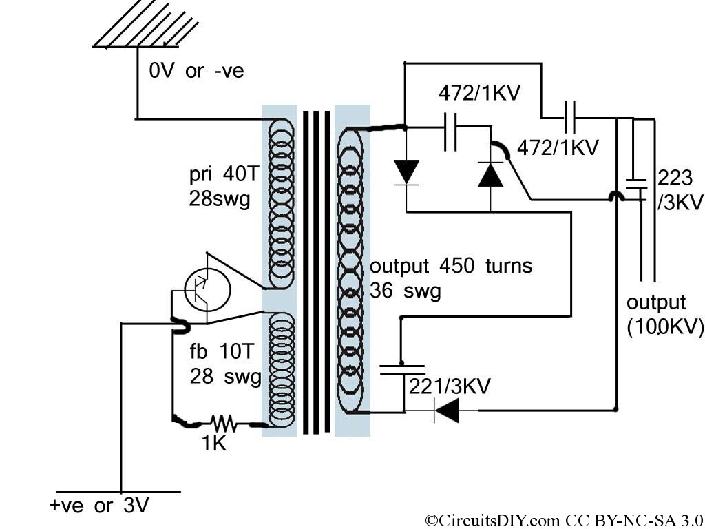
This consist an electric fence in the bat portion which has 5000-10,000 volts passing through them. This is not only mosquito repellent, it's insect The circuit consists of a flyback topology transformer driven by a general NPN transistor 2SD965. The feedback coil of transformer is of 10 turns, the...

Idec Sy4s 05 Wiring Diagram | Free Wiring Diagram
Simple Electric Fencing Circuit. Last Updated on January 10, 2018 by admin Leave a Comment. Some property owners try to construct their own electric fence to skip the equipment cost by connecting a live 230V or even 440V to the metallic wires which run around their property.
A Homemade Fence Charger, Energizer Circuit | Homemade ...
Electric fence wiring diagram | wirings diagram according to earlier, the lines at a electric fence wiring diagram represents wires. Here is an electric fence perimeter protection circuit designed to run on batteries and provide configurable pulses of up to 20kv, to protect a tent perimeter against...

HV Ignition Coil Driver using 555 - schematic | Circuit ...
Planning for permanent electric fencing. Posting komentar untuk wiring diagram electric fence installation. Here is an electric fence perimeter protection circuit designed to run on batteries and provide configurable pulses of up to 20kv, to protect a tent perimeter against bears or other animals.
![[Download 41+] Schematic Electric Fence Circuit Diagram](http://chemelec.com/Projects/Fence-Mon/Fence-Mon-2a.png)
[Download 41+] Schematic Electric Fence Circuit Diagram
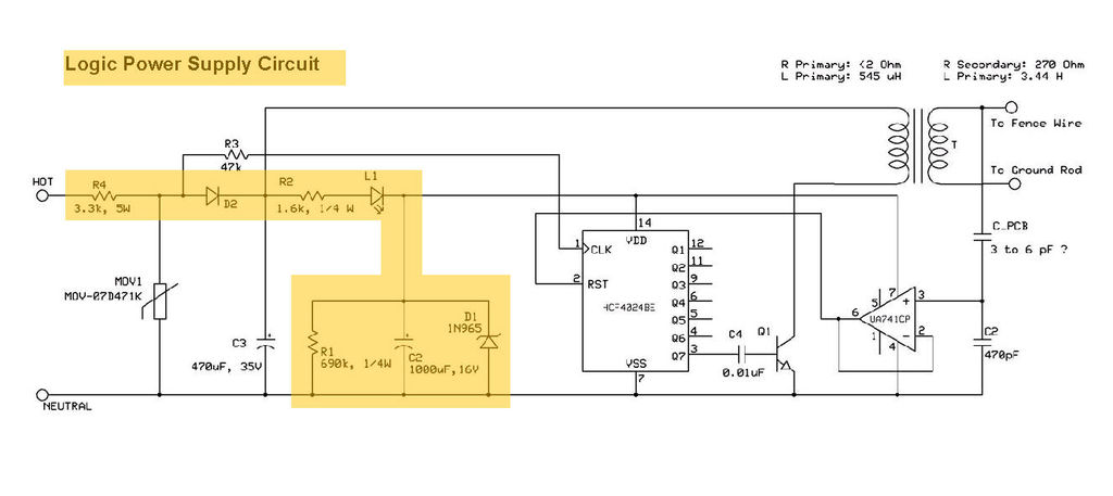
A circuit diagram was created based on the Nikola Teslas Method of utilizing radiant energy Figure 4 shows the construction of a circuit diagram using four diodes and a Housing fence or walls that prevents persons from accidentally contacting energized parts. Electric fence circuit diagram pdf.
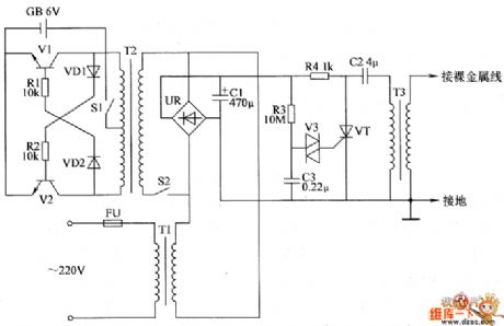
the control circuit of electric fence part 7 - Automotive ...
fence charger circuit please tel me how to design electric fence energizer using microcontroller or using digital ic ? Welcome to our site! EDAboard.com is an international Electronics Discussion Forum focused on EDA software, circuits, schematics, books, theory, papers, asic, pld, 8051, DSP...
ELECTRIC FENCE: ELECTRIC FENCE SCHEMATIC
Of course there’s CircuitTikZ, which I have used in the past and it looks great, but I’ll be honest, it is terrible to write. It’s very tedious, and the circuit elements don’t automatically snap to each other and space themselves, so if you draw the whole diagram and realize you made a mistake after the fact, you have to redo the entire thing to re add the spacings which again is incredibly tedious and time consuming as well. Not to mention It’s also very difficult to read or format CircuitTikZ ...
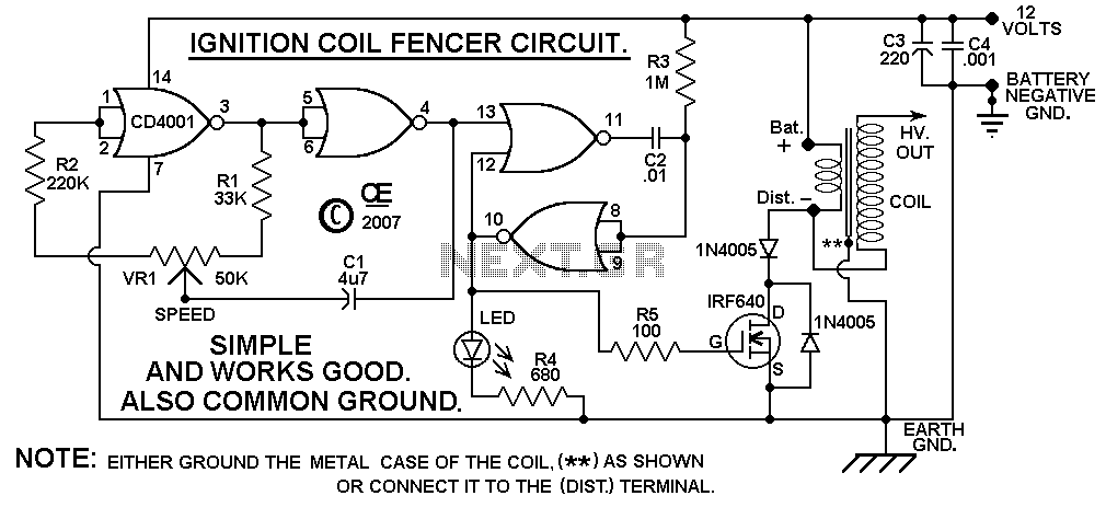
> circuits > Reverse Engineering an Electric Fence Charger ...
Electric Fence Circuit Diagram. Intruders are everywhere and you have. In order to function properly every electric fence needs a good ground. Electric fence circuit for perimeter protection. Once you've done that, run a grounding wire from the charger to all of the grounding posts.

Electric Fence Energizer Wiring Diagram ~ Crapsruleswbs ...
Invisible Fence Wiring Diagram Sample. Electric Fence Circuit For Perimeter Protection U2013 Pocketmagic. Fence Tester Circuit U2022 Electric Fence Energizer Circuit Diagram Integrated System. The Back Shed Electric Fence Energiser. Make This Solar Powered Fence Charger Circuit.
Miniature electric fence circuit used in Mosquito Racket ...
Sep 29, 2015 · Remember one thing, while designing this circuit, that Trigger pulse at PIN 2 must be shorter enough to the OUPUT pulse, so that the capacitor gets enough time to charge and discharge. Here is the practical demonstration of the Monostable mode of 555 timer IC , where we have connected a LED to the output of the 555 IC.

Sunset on the American Tobacco Trail I-40 Pedestrian Bridge in Durham, North Carolina
This is a Electric Fences Circuit Diagram for rural electrification of about fed with just one 9-volt battery, the circuit is small, so it is portable and handy, its operation is based on NE555 integrated circuit which generates pulses with the same time intervals set by resistor R2 together with P1 default...

Red Porsche GT4 at Circuit Paul Ricard (french track) - 3
{{ vm.RepairShellService.searchResultsCount }}
ELECTRIC_FENCE_CHARGER - Power_Supply_Circuit - Circuit ...
Details: electric fence wire diagram wiring diagram database. Architectural wiring diagrams sham the approximate locations and interconnections of Details: 11+ Electric Fence Circuit Diagram. The solar panel collects the energy from the sun and charges. Each is described in detail in the output side...
Electric Fence - 20KV pulses for perimeter defense ...
This is a Electric Fences Circuit Diagram for rural electrification of about fed with just one 9-volt battery, the circuit is small, so it is portable and handy, its operation is based on NE555 integrated circuit which generates pulses with the same time intervals set by resistor R2 together with P1 default...
Electric Fence Energizer Wiring Diagram - Food Ideas
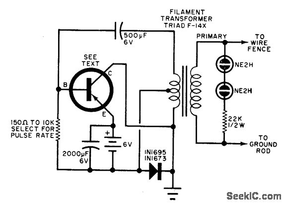
The electric fence charger circuit presented here is basically a high voltage pulse generator. The super high voltage is derived from a commonly used automobile ignition coil. An astable multivibrator is used to generate the required frequency to drive the ignition coil.

ELECTRIC FENCE: ELECTRIC FENCE TESTER CIRCUITS

Solar Wire Fence Diagram | Wiring Diagram - Electric Fence ...
Electric Fence Circuit for perimeter protection - PocketMagic
High-Voltage Pulse Generator under Repository-circuits ...
ELECTRIC FENCE: ELECTRIC FENCE ENERGIZER CIRCUIT DIAGRAM
39 Electric Fencing Circuit Diagram - Wiring Niche Ideas

Unplugged black cord
Index 80 - - Automotive Circuit - Circuit Diagram - SeekIC.com

Electric Fences Wiring diagram Schematic | Wiring And ...
Diagram of electrical fencing around an apiary. | Download ...

How To Wire An Electric Fence Diagram | Electric fence ...


Comments
Post a Comment