39 mercruiser trim sender wiring diagram
According to earlier, the traces at a Mercruiser Trim Sender Wiring Diagram signifies wires. Sometimes, the wires will cross. However, it doesn’t imply link between the cables. Injunction of two wires is usually indicated by black dot to the intersection of two lines. There will be main lines which are represented by L1, L2, L3, and so on. Maintain light tension on the wires from inside the boat, to hold the grommets in the hole. 70198 a b a - Trim Limit Switch Wires b - Trim Position Sender ...10 pages
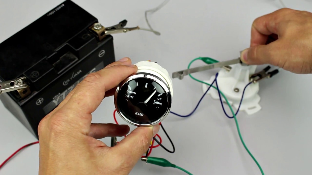
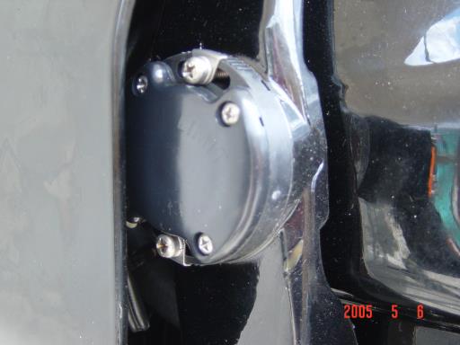
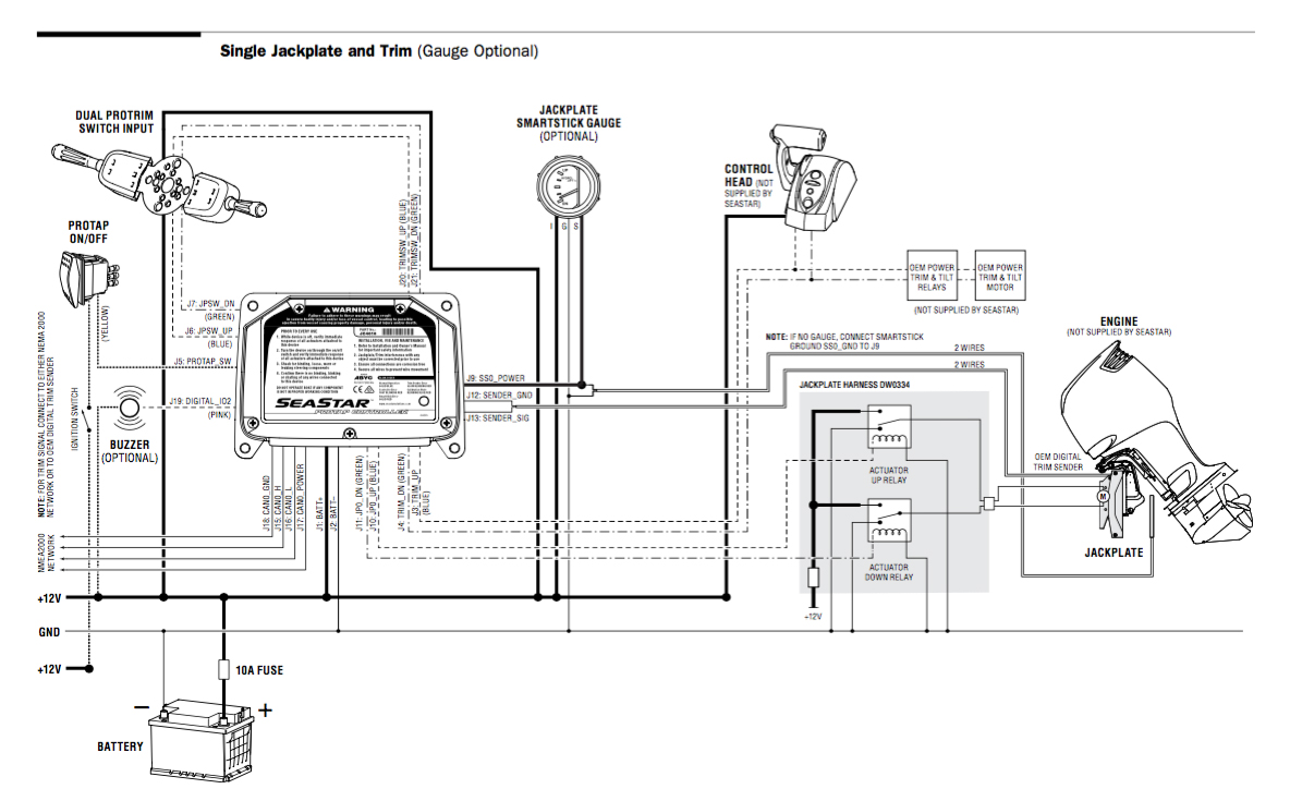
Scroll down to explore all 10 images uploded under Mercruiser Wiring Diagram's gallery . The Trim Sender Switch is used to send a signal to the Trim Gauge so you can see the level of the drive. Description: The Trim Senders are located on either side of the Gimbal Ring. The Trim Limit Switch is mounted to the Port side of the Gimbal Ring.

Mercruiser trim sender wiring diagram
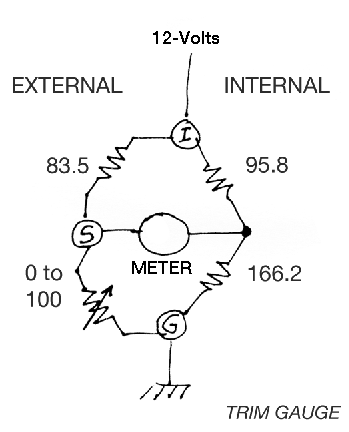
Jul 27, 2005. Messages. 3,102. Jul 24, 2009. #4. Re: Trim sender unit wire broken off, serviceable? if you aren't going to repair it, it is wise to disconnect the sender wires on the inside of the boat. the sender unit is a resistor and does have voltage on the wires. if stray voltage is allowed in the water, you will experience corrosion on ... 12 Jan 2018 — Not sure if I'm answering your question, but the standard colour coding for Mercruiser tilt and trim at the switch would be, 3 wires, Red, ... Mercruiser Trim Sender Wiring Diagram | Wiring Diagram – Mercruiser Trim Sender Wiring Diagram Wiring Diagram contains several comprehensive illustrations that present the connection of varied items. It contains instructions and diagrams for different varieties of wiring techniques and other things like lights, home windows, and so forth.
Mercruiser trim sender wiring diagram. 18 May 2017 — I can't seem to figure ot how to wire the trim & tilt sensors I have the manual ... The limt and sender are identified on the side of them 30 Jul 2010 — Re: trim sender wireing. Used to have mercruiser alpha one. Had to replace with SE106 drive. Let me know if there is any diagrams existing. Common Outboard Motor Trim And Tilt System Wiring Diagrams Mastertech Marine. Mercruiser power trim wiring schematic mercury pump diagram is troubleshooting sender the sterndrive and 898r from 1983 up throttle handle switch club sea ray hydraulic control panel bracket stainless steel bravo one assembly for spare parts system 1973 140 hp goes down cables connected maxum boat 2 wire motor drive ... Trim/Sender Limit Switches. This replaces MerCruiser p/n 805320A1. It will fit all MerCruiser #1 drives made from 1975 to Date including Alpha One, Gen II and Bravo. It cannot be used on boats which have dual station gauges, such as 1 in the cockpit & 1 more on the fly bridge.
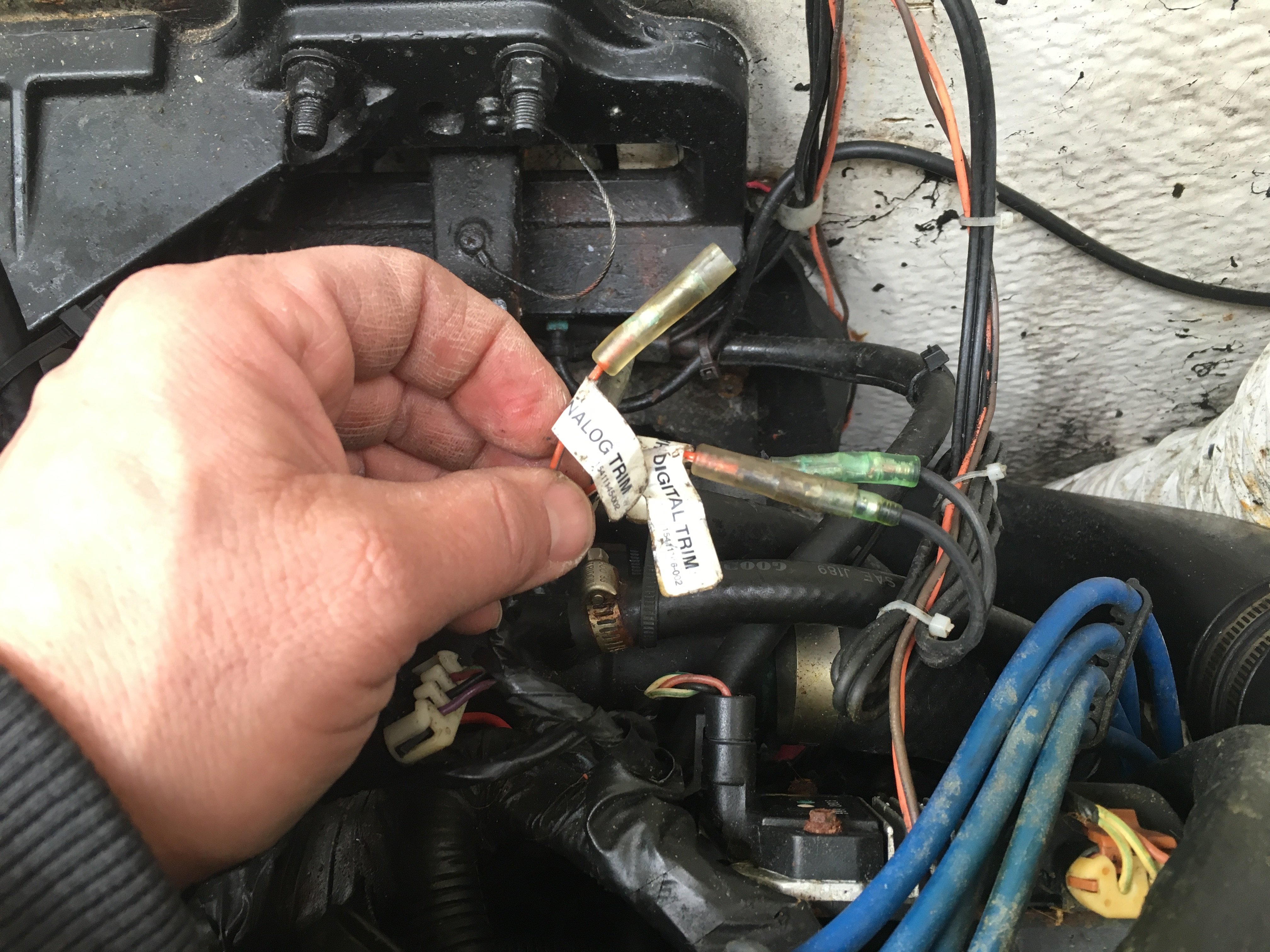
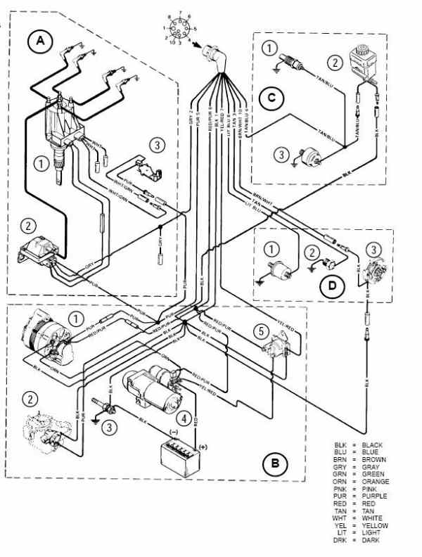
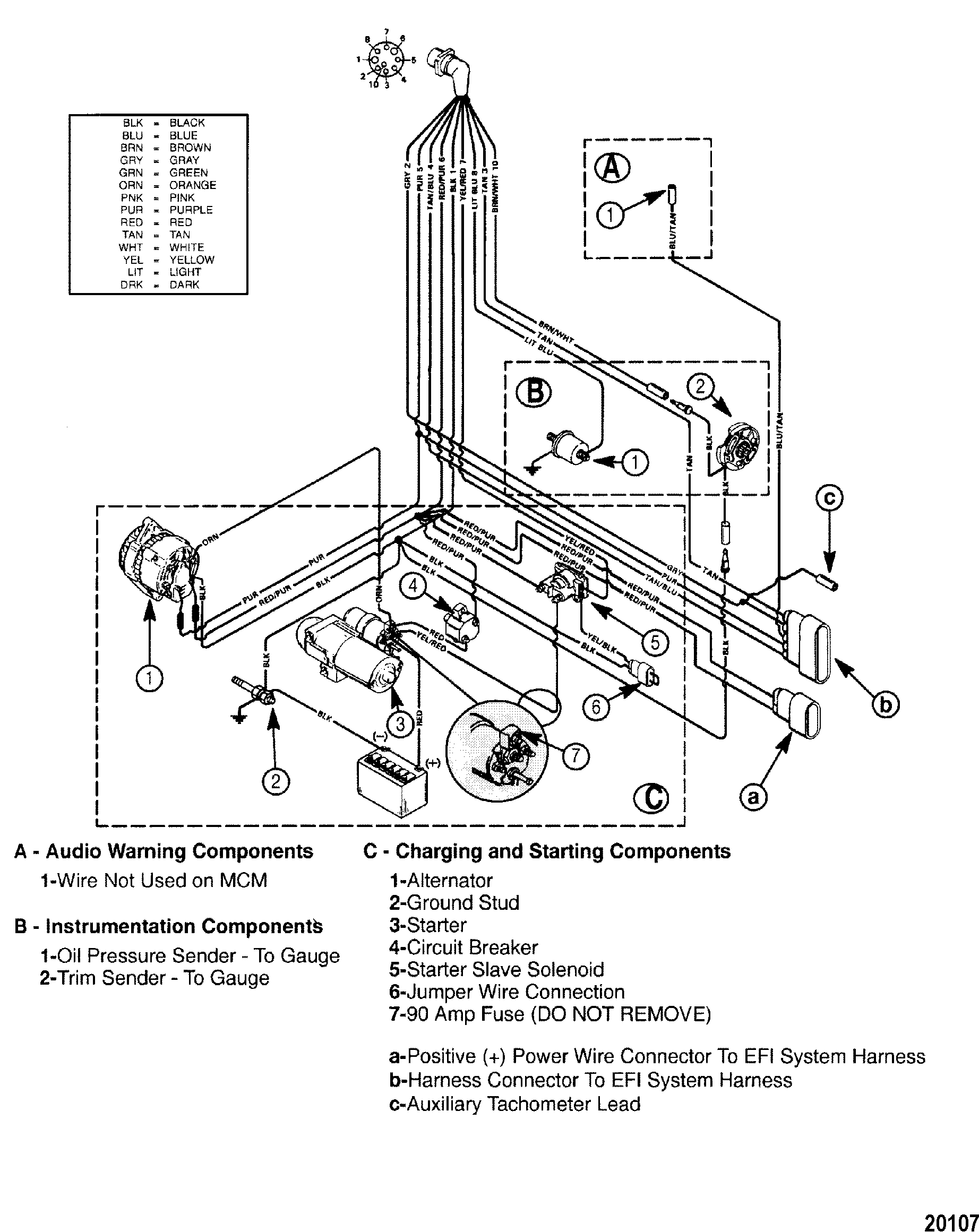
Remove trim wire retainer bolt and retainer. 9. Disconnect trim postition sender wires from engine harness. INSTALLATION. 1. Install new sender wires ...4 pages Aug 25, · Re: Mercruiser trim/tilt wiring For the position sender, the diagram shows one side to ground, and the other side to a brown/white wire, that goes to the connector, and on up to the trim gauge. Look on the back of the gauge and see if there is a br/w wire there. The Trim Limit Switch is mounted to the Port side of the Gimbal Ring. 3 Jan 2015 — I am rebuilding my trim senders limit and position. I do not know where to hook up the wires once you pull them through the transom. The wires should 2 pairs. One pair for trim limit and the other pair for trim sender.Can you determine the pairs? The trim limit will be the 2 male and the other pair will be trim sender. The trim limit will connect to the blue and purple wires near the trim pump. The trim sender wire will be a brown wire and a ground black. Here is a diagram.
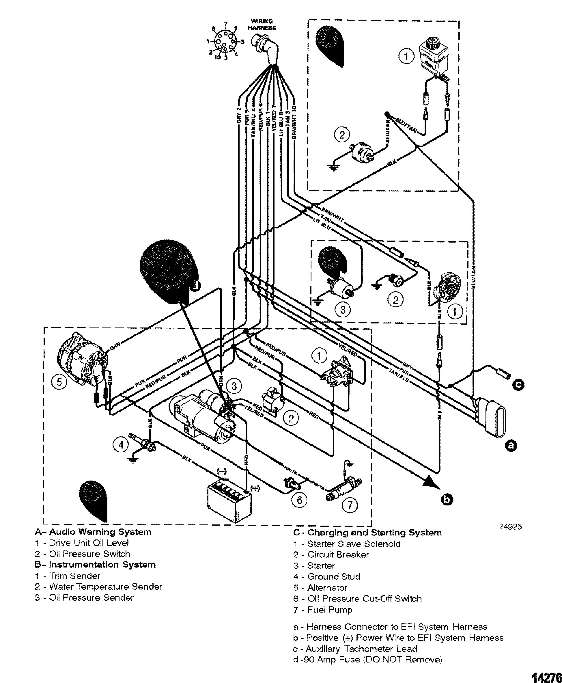
Trim sender, and clean off some of the grease, then retest. ... Shepherd, does this diagram and procedure also apply to non-digital gauges?25 Aug 2014 · Uploaded by Performance Product Technologies This MerCruiser power trim and tilt system is electro-hydraulically operated. Its electrical sub-system consists of a power trim control panel or handle, a pump motor and a trim limit switch, with connecting wiring. Some models may also be equipped with a trim indicator sender. Figure 1 shows a typical system. The hydraulic sub-system contains ... 29 May 2013 — Hello, I bought an older boat that had recently had the previous engine and outdrive replaced. The Trim and tilt senders do not work. Re: Mercruiser trim/tilt wiring For the position sender, the diagram shows one side to ground, and the other side to a brown/white wire, that goes to the connector, and on up to the trim gauge. Look on the back of the gauge and see if there is a br/w wire there. R rjs65 Cadet Joined Jul 25, 2009 Messages 8 Aug 22, 2010 #7
Need wiring for 1987 4 cyl. power trim wiring
Mercruiser Trim Sender Wiring Diagram | Wiring Diagram – Mercruiser Trim Sender Wiring Diagram Wiring Diagram contains several comprehensive illustrations that present the connection of varied items. It contains instructions and diagrams for different varieties of wiring techniques and other things like lights, home windows, and so forth.

MerCruiser Trim Tilt Sender Sending Limit Switch Unit ...
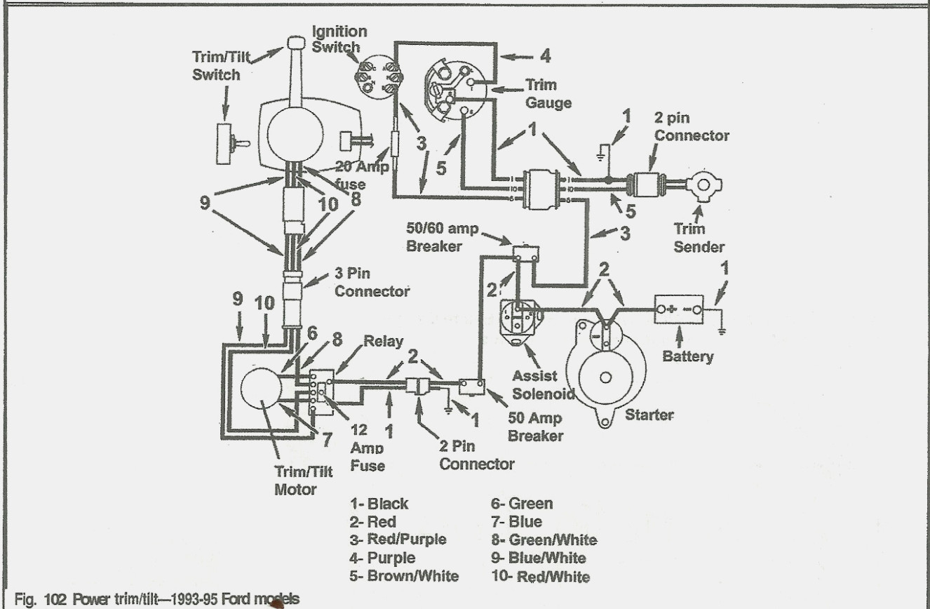
12 Jan 2018 — Not sure if I'm answering your question, but the standard colour coding for Mercruiser tilt and trim at the switch would be, 3 wires, Red, ...

25 Mercruiser Trim Sender Wiring Diagram - Wire Diagram ...
Jul 27, 2005. Messages. 3,102. Jul 24, 2009. #4. Re: Trim sender unit wire broken off, serviceable? if you aren't going to repair it, it is wise to disconnect the sender wires on the inside of the boat. the sender unit is a resistor and does have voltage on the wires. if stray voltage is allowed in the water, you will experience corrosion on ...

Mercruiser Trim Sender Wiring Diagram - Wiring Diagram Schemas
Faria Trim Gauge Wiring Diagram

35 Mercruiser Trim Sender Wiring Diagram - Wiring Diagram List

Bravo Trim switch wiring, HELP :) - Offshoreonly.com

Wiring Diagram: 10 Mercruiser Trim Sender Wiring Diagram

trim sender wiring - Offshoreonly.com

TRIM MOTOR - Pontoon Forum > Get Help With Your Pontoon ...
Mercruiser Trim Pump - Troubleshooting Help - The Hull ...

Mercruiser Trim Sender Wiring | Wire
Mercury Smartcraft Gauges Wiring Diagram. cannot identify ...

I have a mercuiser bravo 3 outdrive, year is 1995. Trim up
Mercruiser Trim Sender Wiring Diagram - General Wiring Diagram

I am looking at a 1987 Wellcraft with a 5.7 Mercruiser ...

MerCruiser 19' 8-Pin Wire Wiring Harness Dash to Motor ...

7 Mercruiser Trim Sender Wiring Diagram - Free Wiring ...
Mercruiser Trim Sender Wiring Diagram | Wiring Diagram
Mercruiser Trim Sender Wiring Diagram | Wiring Diagram

I bought this '86 Ebbtide w/Mercruiser 140/Alpha 2 Stern ...

Closeup of skeleton pelvic model
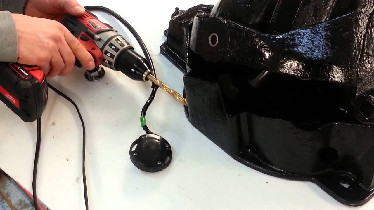
Diy mercruiser alpha/bravo trim sender install - YouTube

Wiring Diagram For 3 Button Single Solenoid Trim Pump For ...
Replacing your Mercruiser Trim Limit and Trim Sender switches

Mercruiser OEM Trim/Tilt Sending Unit Limit Sender Kit ...

Irish Rose

Mercruiser Trim Sender Wiring Diagram - Atkinsjewelry
Wiring Diagram For A 190 Mercruiser Trim Double Solenoid
Mercruiser Trim Sender Wiring Diagram - Hanenhuusholli

Tilt And Trim Wiring Diagram Inboard Mercruiser
Mercury Alpha 1 Shift Interrupter Wiring Diagram

Flowers in Ireland

Closeup of skeleton hand model

26 Mercruiser Trim Gauge Wiring Diagram - Wiring Diagram List

Mercruiser Trim Sender Wiring Diagram - Wiring Diagram Schemas
Mercruiser Trim Sender Wiring Diagram - Atkinsjewelry

Mercruiser Trim Sender Wiring Diagram - Wiring Diagram Schemas
Mercruiser Trim Sender Wiring Diagram | Wiring Diagram


Comments
Post a Comment