39 natural gas compressor station process flow diagram
Compressor Stations. Compressor stations are located approximately every 50 to 60 miles along each pipeline to boost the pressure that is lost through the friction of the natural gas moving through the steel pipe. Many compressor stations are completely automated, so the equipment can be started or stopped from a pipeline's central control room. Natural gas Emission Unit: Cracker Process Oxidizer Emissions . EC -CP-101 . Emission Unit: Regenerative Thermal Oxidizer PC-TO-102 Emission Controls: Low NOx Burners Natural gas Waste Streams Emission Unit: PE Process - Oxidizer Emissions PC TO 103 Fuel and aste
El Paso Natural Gas Company, L.L.C. - Vail Compressor Station | Permit Revision Application Trinity Consultants 1-1 1. EXECUTIVE SUMMARY The El Paso Natural Gas Company, L.L.C. (EPNG), a Kinder Morgan Company, provides natural gas transportation

Natural gas compressor station process flow diagram
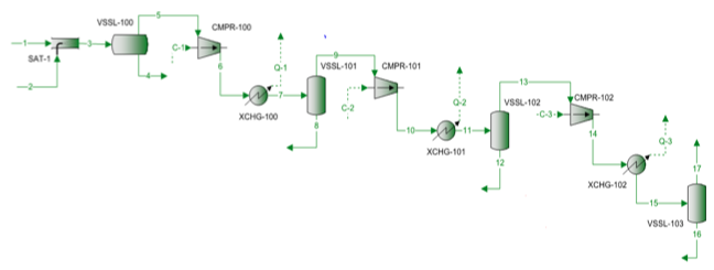
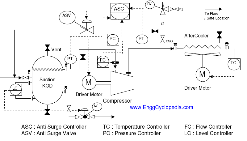
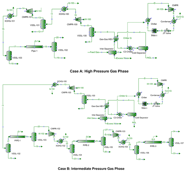
Takes advantage of the cooling ability of hydrocarbons available in the natural gas to help in the liquefaction process. Numerous expansion stages are required to achieve desired temperatures. Considered as a safer method because there are no external refrigerants needing storage. The following figure-1 represents a typical process flow diagram (PFD) for a centrifugal compressor system. Common equipments included in such systems are compressors, driver motors or turbines, suction knock out drums (KOD) to remove traces of liquid from the gas going into the centrifugal compressor and aftercoolers which help lower the temperature of the discharge gas from compressor. US Natural Gas Pipelines and Compression Stations - 2.3 million miles of pipelines - 850-900 mainline compressor stations, 800-900 booster stations (+ 15,000 gas gathering machines) - Average age of pipeline compressors: 25-30 years - Consume/lose about 2.5-3.5% of US NG = 0.7 tcf/y = 3-4 billion US Dollars per year
Natural gas compressor station process flow diagram. Wet natural gas is rich in liquid hydrocarbons, such as oil and NGL. Dry natural gas is natural gas that remains after (1) the liquefiable hydrocarbon portion has been removed from the gas stream (i.e., gas after lease, field, and/or plant separation), and (2) any volumes of non-hydrocarbon gases have been Most natural gas-fired reciprocating engines are used in the natural gas industry at pipeline compressor and storage stations and at gas processing plants. These engines are used to provide mechanical shaft power for compressors and pumps. At pipeline compressor stations, engines are used to help move natural gas from station to station. Interviews with gas compressor station Senior Experts from Italy's TSO; Websites of European gas operators. A total number of 56 compressor stations located all around the European Union have been identified and assessed for this study, in particular 9 compressor stations in Germany (Bunde, Eischleben, Lippe, Mallnow, Why Do We Compress Gas? Compression is used in every sector of our industry when conditions do not normally exist for various processes to take place. Producers ...
diaphragm compressor used to compress hydrogen gas to 6000 psi (41 MPa) for use in a prototype compressed hydrogen and compressed natural gas (CNG) fueling station built in downtown Phoenix, Arizona by the Arizona Public Service company (an electric utilities company). Reciprocating compressors were used to compress the natural gas. Natural Gas Industry Methane Emission Factor Improvement Study ... 48 reciprocating compressors at transmission compressor stations. Emissions from other fugitive sources such as valves, flanges, and other components were also measured in a few locations. ... Centrifugal Compressor Lube Oil System Process Flow Diagram (Picard, 2011) ..34 natural gas compressor station process flow diagram. 10 August 2020. 0000021899 00000 n 0000021996 00000 n 0000022464 00000 n 0000003536 00000 n The quality of natural gas can have a significant impact on the operation of regulating and metering stations. The gas should be pipeline quality gas, free of most impurities and condensates. The conditioning of natural gas is the set of techniques used to remove any remaining or subsequently formed liquids, condensates, or solids from gas flows.
The gas will flow downward in the bed and should be depressurized in about 20 minutes. 7.4.3.2 Heating. Once the bed is depressurized, the heating step can begin. The residue gas is compressed by the regeneration gas compressor, flows through the bypass valve to the regeneration gas heater, and is heated to about 300°C. Compressor Station. Station Retrofits and Reversals. Process Flow Diagrams. Jacket Water and Gas Cooling. Pumping Systems. Fugitive Emissions Studies. AutoCAD Civil 3D and CadWorx. 2 COMPRESSOR SOLUTIONS FOR LNG TERMINAL APPLICATIONS GROWING NATURAL GAS MARKETS Demand for environmentally friendly natural gas as a fossil fuel will continue to increase over the long term. Replacing the liquid fossil fuels of diesel, gasoline and oil with natural gas would reduce global carbon dioxide emissions by about 30%. The total feed gas volumetric flow rate was 101 MMSCFD (2.86×10 6 Sm 3 /d). Table 1. Feed gas analysis. Figure 1. Compressor polytropic head and best efficiency point. Figure 2. Compressor polytropic efficiency. Results and Discussions
Natural Gas Compressor station components - AONG website
One or more compressor stations are needed to keep the required gas flow in the pipeline. Internal friction will cause a pressure drop along the pipeline that increases with flow. Thus, the starting pressure must be high enough to maintain design capacity flow up to the final terminal.

Flow diagram of the Haradh Gas Processing Plant ...
Natural Gas Industry Process Flow Diagram. Create Process Flow Diagram examples like this template called Natural Gas Industry Process Flow Diagram that you can easily edit and customize in minutes. 1/16 EXAMPLES.
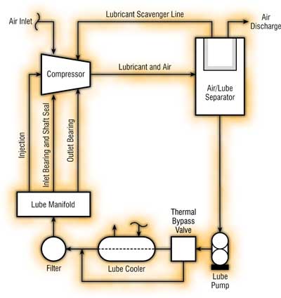
Natural Gas Compressors and Their Lubrication
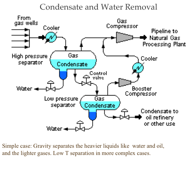
The heaters ensure that the temperature of the natural gas does not drop too low and form a hydrate with the water in the gas stream. Natural gas hydrates are crystalline ice-like solids or semi-solids that can impede the passage of natural gas through valves and pipes. A generalized natural gas flow diagram is shown in Figure 12.2 [7]. After initial scrubbing to remove particles, the first step in natural gas processing is the removal of condensate (oil) and water that is achieved by ...

Gas works parks with Seattle downtown in background
E. Shashi Menon Ph.D., P.E., in Pipeline Planning and Construction Field Manual, 2011 Publisher Summary. This chapter discusses the number and size of compressor stations required to transport gas in a pipeline. The optimum locations and pressures at which compressor stations operate are determined based on the pipeline flow rate, allowable pipe operating pressures, and pipeline topography.
How to Estimate Compressor Efficiency? | Campbell Tip of ...
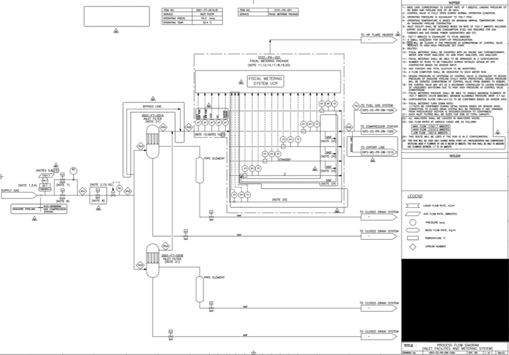
As gas enters the compressor station from the pipeline, it passes through a natural gas scrubber vessel. This vessel is designed to remove free liquids, dirt or ...2 pages
This Is The Given Pfd's For Natural Gas Compressio ...
Our Process, Mechanical Engineering, and Design team has experience in: • Gas Plant / Balance of Plant • Natural Gas compressor stations • Pipelines • Valve stations and manifolds • Terminals • Tank Farms • PHA facilitation Our services and deliverables include: • Process simulation • Process Flow Diagrams • Piping and Instrumentation Diagrams • Equipment Sizing and ...

Natural Gas Compressor station components - AONG website
Storage of natural gas incident to transportation (i.e., gas taken from a pipeline during non-peak periods and placed in storage fields, then returned to the pipeline when needed) is not covered. Storage fields include, but are not limited to, depleted oil and gas reservoirs, aquifers, mines, or caverns. Q S & As S TATI ONARY S OURCE Q.

Diaphragm Compressors | Membrane Process Gas Compressors ...
This compressor will be used to evacuate a vessel at the end of a batch process. It will be used in a production facility that will perform 6 batch operations in a 16 hour ... or even natural gas are too generic.) ... flow expected from the compressor will be 20 SCFM. This is what will be used to size the

Gas Compressor: Gas Compressor Diagram
With new demands as well as changes in the flow of gas along CPG's pipeline, compressor stations that previously supplemented the process have become critical. Columbia needed to maximize throughput and reduce unplanned downtime of its compressors to keep up with the increasing market demands-especially in places where the compressor station ...
Hvac Systems new: Flow Diagram Of Hvac System
Utilizing compressors, natural gas compression stations (NGCS) supply the ... and thus reduce the required flow rate, the size of the facility, and the pump ...

Troubleshooting At The Dehydration & Compression Station ...
The major sources of air emissions at Station 7 are the two gas turbine units, Unit 7B and Unit 7C. Through valving, natural gas can be routed through either one or both compressors. In addition, the station can be bypassed entirely. A process flow diagram and facility plot plan are presented in Appendix A.
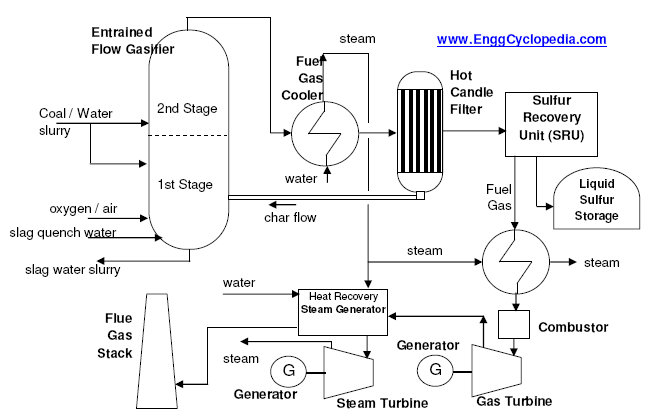
Typical Process Flow Diagram of IGCC plant - EnggCyclopedia
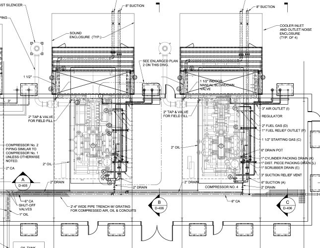
Two Notes: (1) Hilti KB-TZ2 may be directly substituted for TZ in this detail. (2) In the event that SDC C applies and the enclosure (s) in question is “unimportant (i.e., Ip = 1.0 per ASCE 7),” then the enclosure (s) is seismically exempt (per ASCE 7 para. 13.1.4) and only gravity loads need be considered.

Owl. Animal photos at The Natural History Museum, London, England, January 2020.
Process Flow Diagram Q High Temperature (Ambient) Q Low Temperature (Sub - Ambient) Condenser Suction Drum Compressor Heat Exchanger J-T Valve AccumulatorLNG out Rough “rule of thumb”: 35 MW of shaft power per Mt/a for “efficient” liquefaction processes Where the magic happens GAS in Large amount of Energy Input Driver (not shown ...

MACHINERY, in a Nutshell: December 2015
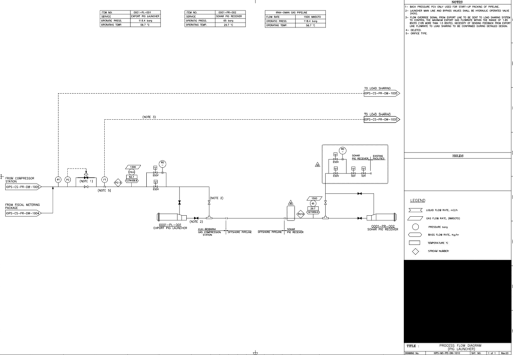
The conditioned gas will be routed via new pipeline to gathering station. The typical process flow diagram of natural gas compression and production system is shown below (Fig. 1). Fig. 1. Natural gas compression and associated pipeline network system. 2.2 Risk assessment methods

Natural Gas Pipeline System (Source: PHMSA 2005-2011 ...
Supply and demand can also be a factor at times in the level of compression required for the flow of the natural gas. Liquid Separation and Filtering at Compressor Stations - Compressor stations typically include scrubbers, strainers or filter separators which remove liquids, dirt, particles, and other impurities from the natural gas. Though ...

Wellhead Natural gas Oil well Gas lift Compressor ...
Natural Gas pipeline you typically find compressor stations, valve stations and meter stations. Larger facilities such as gas storage, gas processing and fractionators in midstream can also be considered station. Basically stations are remote facilities whose operation impacts the operation of the pipeline. Compressor Stations Each compressor ...
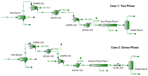
Transportation of Natural Gas in Dense Phase | Campbell ...
In the oil and natural gas sector, the most prevalent types of compressors used are reciprocating and centrifugal compressors. For the purposes of this paper, a reciprocating compressor is defined as: A piece of equipment that increases the pressure of a process gas by positive displacement, employing linear movement of the driveshaft.

Ha transcurrido algun tiempo desde que hice esta foto que puede parecer algo cursi y, (sin pretenderlo) con cierto aire pictorialista. Ese paisaje bucólico está ubicado en un parque natural y, afortunadamente permanece inalterado.
natural gas compressor station process flow diagram ; Cooling method: air cooled or water cooled ; working medium: natural gas ; Application: natural gas station.Packaging Details: natural gas compressor pri...Outlet pressure: 1-3625 psiApplication: natural gas stationType: reciprocating piston$2,000.00 · In stock

Whistleblower: EPA Officials Covered Up Toxic Fracking ...
Natural gas compressors or compressor stations are critical to a natural gas pipeline system. These compressors’ primary goal is to increase gas pressure and reduce its volume to make it distributable to the market. However, they can also process natural gas liquids (NGLs) out of the compressed gas. This application is especially relevant to ...
Services - Industrial Mechanical Inc.
Mar 26, 2015 · Understanding Natural Gas Compressor Stations. Compressor stations are an integral part of the natural gas pipeline network that moves natural gas from individual producing well sites to end users. Figure 1. A separator filters out liquids, solids, and other particulate matter that may be in the gas stream.

Evening at Natural History Museum
PROCESS FLOW DIAGRAM ... Process Products NAICS SIC Natural Gas Transmission Natural Gas 486210 4922 Provide a general description of operations. Lost River Compressor Station is a natural gas transmission facility covered by Standard Industrial Classification (SIC) Code 4922. The station has the potential to operate twenty-four (24) hours per ...

Angle Lake light rail station, SeaTac, WA
compressor stations demonstrated that the average value of gas that could be saved by instituting a DI&M program at a compressor station is $88,239 per year, at an average cost of $26,248 per station. Introduction . Transmission compressor stations boost pressure at various points along natural gas transmission pipelines to

How a Compressor Station Works - YouTube
A general process flow diagram of the compression station is shown in Figure 1. 2. Relief Analysis For this case study, twenty separate compressor stations were analyzed. Specifically, the steps required for performing the analyses, different applicable scenarios, and all the concerns identified Figure 1: Process flow diagram of Compressor Station
Gas Compressor: Gas Compressor P&id
Sep 22, 2015 — accomplished by submitting a process flow diagram indicating custody transfer points and the natural gas flow. However, the DAQ reserves the ...

Gas Compressor: Gas Compressor P&id
US Natural Gas Pipelines and Compression Stations - 2.3 million miles of pipelines - 850-900 mainline compressor stations, 800-900 booster stations (+ 15,000 gas gathering machines) - Average age of pipeline compressors: 25-30 years - Consume/lose about 2.5-3.5% of US NG = 0.7 tcf/y = 3-4 billion US Dollars per year

MEC&F Expert Engineers : ABOUT U.S. NATURAL GAS PIPELINES ...
The following figure-1 represents a typical process flow diagram (PFD) for a centrifugal compressor system. Common equipments included in such systems are compressors, driver motors or turbines, suction knock out drums (KOD) to remove traces of liquid from the gas going into the centrifugal compressor and aftercoolers which help lower the temperature of the discharge gas from compressor.

Natural Gas Odorization Monitoring For Safety And ...
Takes advantage of the cooling ability of hydrocarbons available in the natural gas to help in the liquefaction process. Numerous expansion stages are required to achieve desired temperatures. Considered as a safer method because there are no external refrigerants needing storage.
This Is The Given Pfd's For Natural Gas Compressio ...

1 Flow diagram of a simple gas turbine power plant ...
Low Pressure Versus High Pressure Dense Phase Natural Gas ...

P&ID's, Hazardous Area Classification, Emergency ...

Pipeline Stations: From Pre-Commissioning to Start-Up ...
Natural Gas Diagram - Solving your problem about wiring ...

Giant Hurricane Space
Natural Gas Processing: Dehydration, Refrigeration and ...
-crude-oil-distillation-unit---pfd.png--diagram-flowchart-example.png)
Natural gas condensate - PFD | Jet fuel mercaptan ...
UGI Energy Services Natural Gas Compressor Station Project ...

КомпреÑÑÐ¾Ñ€Ð½Ð°Ñ ÑÑ‚Ð°Ð½Ñ†Ð¸Ñ Â«ÐŸÐ¾Ñ€Ñ‚Ð¾Ð²Ð°Ñ»

Acid Gas & Sour Gas Service | Gas Compressor Applications ...


Comments
Post a Comment