39 transformer wiring diagram single phase
A transformer wiring diagram can be found printed on the transformer nameplate or inside the cover to the wiring compartment. The leads or terminals are marked with Hs and Xs. In general, connecting individual transformers together requires that: Their voltage ratings must be equal. Their percent impedance must be equal. Single-phase pad-mounted ranch runner transformer Product Scope: kVA: 10-50 Primary Voltage: 2400-14,400 V Secondary Voltage: 120-600 V B C A 16" (19" for 150 kV BIL) H1A H1B X1 X2 X3 B C 30" 16" (19" for 150 kV BIL) H1A H1B X1 X2 X3 Figure 2. Single-phase pad-mounted Shrubline. Figure 3. Single-phase pad-mounted MaxiShrub. Figure 4. Single ...
There are hundreds (or even thousands) of these on most radial distribution feeders. Compared to the balanced three-phase transformers commonly found in ...

Transformer wiring diagram single phase
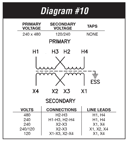
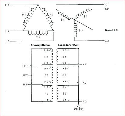
In a wye connection, the end of each coil is connected to the incoming power lines (primary side) or used to supply power to the load or loads (secondary side). 480 To 120/240 Transformer Wiring. a volt primary transformer with a volt secondary is operated at volts, regardless of whether the source is three phase 3-wire or three phase 4-wire. .. example: A 10 kVA transformer, / volt secondary is to service an 8 kVA . Single Phase Transformer Primary and Secondary wiring. ELECTRICAL CONNECTION DIAGRAMS. 155. GENERAL. ACME® TRANSFORMER™ WIRING DIAGRAMS ... 1 phase. X2 to X0. X3 to X0. 19. PRIMARY: 380 Volts Delta.
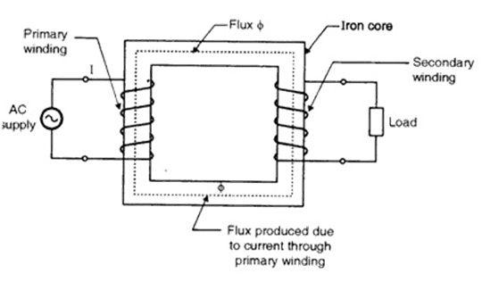
Transformer wiring diagram single phase. According to earlier, the lines in a Single Phase Transformer Wiring Diagram signifies wires. Sometimes, the wires will cross. However, it does not imply connection between the wires. Injunction of two wires is generally indicated by black dot in the junction of two lines. Transformers increase voltage, decreasing current in power systems. Lower I means less power loss due to I2R losses in lines, cables, transformers, etc Generator Step up transformer I V Step down transformer V I Three phase transformers 3 single-phase units can form 3-phase bank or Single three-phase transformer (3 separate cores in a single tank) 480v single phase transformer wiring wiring diagram standard. Architectural wiring diagrams work the approximate locations and interconnections of receptacles, lighting, and surviving electrical facilities in a building. Interconnecting wire routes may be shown approximately, where particular receptacles or fixtures must be on a common circuit. The HPS IMPERATORTM series of machine tool industrial molded control transformers are available in many standard offerings. This wiring hook-up instruction ...9 pages
Wiring Diagram Single Phase Transformer. By Margaret Byrd | December 28, 2021. 0 Comment. Circuit diagram and photo of the common single phase center tapped scientific transformer connections electricity forum figure 4 17 connected to give 120 240 volt three wire service mks mksh k factor dry type distribution marcus transformers electrical a2z ... A single-phase, as is the case in one pole mounted distribution transformer, as well uses the neutral from a three phase system. The substation feeding the system has a wye with grounded secondary transformer, and even in the event your xformer is single-phase, that phase is more than likely part of a three phase system. On an “Isolation transformer” there is no direct electrical connection ... The advantages of building a single three phase transformer is that for the same ...14 pages SINGLE PHASE TRANSFORMER WIRING DIAGRAM. CENTRE TAPPED SECONDARY. NOTE: 220/240V PRIMARY VOLTAGE. AND 110V SECONDARY VOLTAGE. RANGES ARE SHOWN FOR GUIDANCE.1 page
Single Phase Transformer Wiring Diagram. Single phase transformer connections the electricity forum circuit diagram and photo of common center tapped scientific figure 4 17 connected to give 120 240 volt three wire service mks mksh k factor dry type distribution marcus transformers working principle applications electrical4u v connection for ... Single-phase transformer to 7200V primary with 120/240V secondary. Fig_4-2 – Single-phase transformer with one bushing that connects to one single-phase primary 7200V. Center tap grounded to earth ground. Provides three-wire 120/240V to the system. One reason I like this is because I managed to break a bushing off of a couple of the transformers. ELECTRICAL CONNECTION DIAGRAMS. 155. GENERAL. ACME® TRANSFORMER™ WIRING DIAGRAMS ... 1 phase. X2 to X0. X3 to X0. 19. PRIMARY: 380 Volts Delta. 480 To 120/240 Transformer Wiring. a volt primary transformer with a volt secondary is operated at volts, regardless of whether the source is three phase 3-wire or three phase 4-wire. .. example: A 10 kVA transformer, / volt secondary is to service an 8 kVA . Single Phase Transformer Primary and Secondary wiring.

Step Up Transformer, To, Wiring Diagram Perfect 480V ...
In a wye connection, the end of each coil is connected to the incoming power lines (primary side) or used to supply power to the load or loads (secondary side).

480v To 240v Single Phase Transformer Wiring Diagram ...
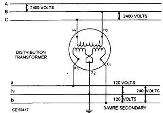
Figure 4-17.Single-phase transformer connected to give 120 ...

480V To 240V Transformer Wiring Diagram | Wiring Diagram

OT - 208V Three Phase Transformer Question

Spooky vibes at abandoned cell tower

The equivalent circuit of the single phase transformer ...
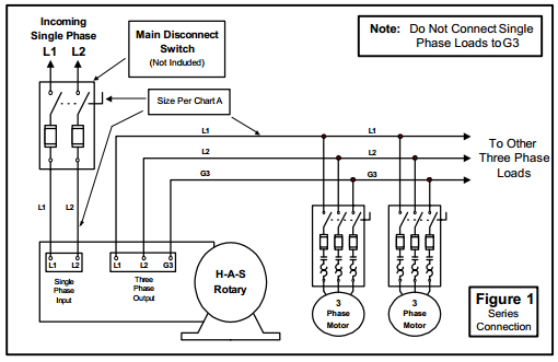
How to Install H-A-S Rotary Phase Conversion System

Three-Phase to Single-Phase Transformer - CR4 Discussion ...
Single Phase Transformer Wiring Diagram - Complete Wiring ...

Inverter Circuit- 12V DC to 220V AC Power Converter,Mosfet ...
Square D 75 Kva Transformer Wiring Diagram - Wiring Diagram

The equivalent circuit of the single phase transformer ...

Image from page 245 of "The Street railway journal" (1884)

Monochrome, Power Lines, Winlaton Mill, Tyne & Wear, England.

Image from page 247 of "Annual report 1919" (1919)
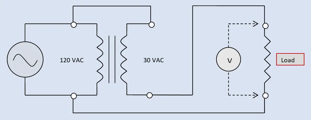
Buck-Boost Transformer Working Principle | Electrical Academia

Bath Robe Mannequin Shoot

480V To 120V Transformer Wiring Diagram | Fuse Box And ...
What is single phase transformer mean? - Quora

Hammond Transformer Wiring Diagram 373

Wye and Delta Connections of Single-Phase Transformers

Image from page 307 of "Cyclopedia of applied electricity : a general reference work on direct-current generators and motors, storage batteries, electrochemistry, welding, electric wiring, meters, electric lighting, electric railways, power stations, swit

Image from page 268 of "Development and electrical distribution of water power" (1908)
Transformer Wiring Basics
3 Phase Transformer Wiring Diagram | Cadician's Blog

Step Up Transformer, To, Wiring Diagram Professional 2 ...
Single Phase Transformer Wiring Diagram For Your Needs
Theory of Operation of Single-Phase Transformers - Custom ...

Topic: Single-Phase Transformer Wiring

photo inside a photo.

Sea shoreline
480 Volt Three Phase Transformer Wiring Diagram - Wiring ...

240V Transformer Wiring Diagram - Wiring Forums

Multi Ratio Current Transformer Wiring Diagram | Free ...

240V Transformer Wiring Diagram - Wiring Forums

Electrical Wire Size Chart 3 Phase Brilliant 75 ...
![[KD_7709] Single Phase Transformer Wiring Diagram In ...](https://static-assets.imageservice.cloud/190296/single-phase-transformer-wiring-diagram-in-addition-zig-zag.jpg)
[KD_7709] Single Phase Transformer Wiring Diagram In ...

BASIC PARTS OF A SINGLE-PHASE DISTRIBUTION TRANSFORMER AS ...


Comments
Post a Comment