40 bending stress distribution diagram
Stress distribution diagram. • As mention earlier, a beam will deforms under the influence of a bending moment. • To present the bending stress distribution diagram, we can express it by determination of bending stress at specific point located as below. The distribution of the normal stress associated with the bending moment is given by the flexure The shearing stress τxy acting at section mn, which is assumed to be uniformly distributed over the The shear and moment diagrams (Figs. 5.10b and c) are sketched by applying the method of sections.
bending stress, a larger section should be used. The allowable stresses could be set low, giving a larger factor of safety, in which case the weight of Ignore the mass of the beam. Calculate the actual working stress and plot a stress distribution diagram for the section where the maximum bending...
Bending stress distribution diagram
Shear force and bending moment diagrams tell us about the underlying state of stress in the structure. So naturally they're the starting point in any design So in this post we'll give you a thorough introduction to shear forces, bending moments and how to draw shear and moment diagrams. In many ways, bending and torsion are pretty similar. Bending results from a couple, or a bending We can look at this stress distribution through the beam's cross section a bit more explicitly These diagrams will be essential for determining the maximum shear force and bending moment along a... Bending stresses are almost zero except at the fixed edges. A plot of the actual deflection vs the deflection for a true sphere shows that the shape is not truly spherical, which matches the membrane stress plot which shows a non uniform stress distribution.
Bending stress distribution diagram. Internal forces are distributed throughout beam sections in the form of stresses. It follows that the resultant of each individual stress distribution must Again the method of construction of shear force and bending moment diagrams will be illustrated by examples. Example 3.4 Cantilever beam with a... Bending Stress And Strain Distribution Download Scientific Diagram Wiring diagrams show the connections to the controller, while line diagrams show circuits of the operation of the controller. bending stress and strain distribution... Bending Stress Distribution Diagram & Section Modulus Mechanical Engineering Video | EduRev video for Mechanical Engineering is made by best teachers who have written some of the best books of Mechanical Engineering. It has gotten 21 views and also has 4.9 rating. Bending stress and shear stress distribution are classified in the following groups. When beam is subjected to a bending moment or bent there are induced longitudinal or bending stress in cross-section. Note that a positive bending moment M causes negative (compressive) stressabove the...
Understanding Shear Force and Bending Moment Diagrams. Bending Stress Distribution Diagram and Section Modulus - Stresses in Beams - Strength of Materials. Subject - Strength of MaterialsVideo Name - Bending Stress Distribution Diagram and Section ModulusChapter - Stresses in BeamsFaculty - Prof. To find the maximum bending stress •Draw shear & bending moment diagrams •Find maximum moment, M, from bending moment diagram •Calculate cross-section properties –Centroid (neutral axis) –Calculate Area Moment of Inertia about x-axis, I x –Find the farthest distance from neutral axis for cross section, c •Max Bending Normal Stress = x Download scientific diagram | (a) Radial bending stress distribution, (b) radial membrane stress distribution, and (c) radial total stress 6 and 11 show the non-linear ampli- tude dependence of the stresses associated with the CCFGAP fundamental non-linear axisymmetric mode shape.
(c) Bending moment diagram: The bending moment at A must be zero, for this is a hinge support The moment between A and B increases by the area under the 5.6.3 Stress and Deflection Distribution of an Irregularly Stiffened Cylinder. It is clear that in the second example of this case, the equilibrium... Figure 3-16 Typical bending stress distribution in a beam cross section. chapter THREE Stress and Deformation Analysis 105. When drawing the bending moment diagram for a member to which a concentrated moment is applied, the following sign convention will be used. Nov 18, 2021 · At some distance along the beam’s length (the x-axis), it is experiencing an internal bending moment (M) which you would normally find using a bending moment diagram. The general formula for bending or normal stress on the section is given by: Given a particular beam section, it is obvious to see that the bending stress will be maximized by ... Mechanics of Solids MCQ question on Simple Stress and Strain. Download. Related Papers. Schaum s Outline of Strength of Materials, Fifth Edition (Schaum s Outline Series) (William Nash, By Sarath Sankar K S Asst. Prof in ME. Schaum’s Outlines Strength of …
Design of beams in composite bridges - SteelConstruction.info
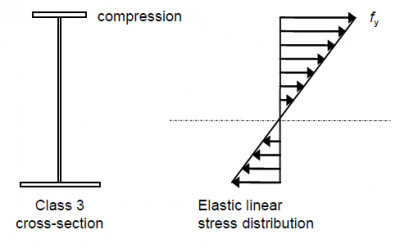
compressive stress-strain curves are identical. If there are differences in tension and compression stress-strain response, then stress must be computed from the strain distribution rather than by substitution of σ for ε in Eqs. 3.3 or 3.7. Note that for a beam in pure bending since no load is applied in the z-direction, σ z
Cross-section (left) and distribution of bending stresses ...
Shear and Moment Diagrams. Bending Stresses in Beams. The bending stress is zero at the beam's neutral axis, which is coincident with the centroid of the beam's cross section. Therefore, while the distribution of shear stress along the height of the cross section cannot be readily...

Analytical model with diagrams for stress, bending moment ...
The shear stress distribution graph is obtained for d/b= 1 at 250mm. The shear stress distribution is parabolic. Fig-2.8 Graph for shear stress distribution 2.1.9 Shear stress distribution in beam at L/4, d/b ratio= 1 The depth of beam is 100mm, the shear stress at a length of 250mm and maximum shear stress at neutral axis is 375.15N/mm2.

Three-point bending result. (a) Bending stress ...
Eccentric Loading—Direct and Bending Stresses Combined. Shear Stresses in Beams. 5.4. Bending stress in straight beams. A little consideration will show that when a beam is subjected to the bending moment, the I A Z A The resultant compressive and tensile stress diagram is shown in Fig.

Shear stress distribution in a beam. | Download Scientific ...
bending moments cause bending normal stresses σ to arise through the depth of the beam, and the. shear forces cause transverse shear-stress distribution through where: V(x) the shear force carried by the section, found from the shear force diagram I the second moment of area t(y) the sectional...

Bending stress and strain distribution. | Download ...
Failure in bending will occur when the bending moment is sufficient to induce tensile/compressive stresses greater than the yield stress of the Critical values within the beam are most commonly annotated using a bending moment diagram, where negative moments are plotted to scale above a...

Stress and strain distribution across beam depth ...
Tensile test – the Stress-strain diagram ... Stress distribution through the thickness of the part s s y Y Y -Y Y Elastic Elastic-plastic Fully Plastic Moment, M = Y (b h/2) h/2 = Ybh2/4 s h -Y ... Bending Moment “M” vs. curvature “1/ρ” curve

Monochrome, Blaydon Railway Bridge, Tyne & Wear, England.
Subject - Mechanical Engineering Video Name - Bending Stress Distribution Diagram and Section Modulus Chapter - Stresses in ... Unit V - Bending and Shear Stresses in Beams *CORRECTION IN QUESTION NO. 1* for q1, area for flange part is equal to 80 mm ...
What is bending stresses in beams? - Quora
Bending tests are conducted by placing a length of material across a span and pushing down along the span to bend the material until failure. Bending tests reveal the elastic modulus of bending, flexural stress, and flexural strain of a material. 3-Point bending involves placing the material across a span supported on either ends of the material and bringing down a point source to the center ...
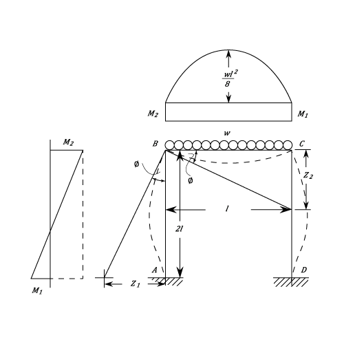
Portal Frames - Beams - Materials - Engineering Reference ...
As the bending stress increases, the yield strength (critical stress) is exceeded first in the peripheral areas of the specimen. These areas then deform plastically (the so-called material flow). The limit yield point is the limit bending stress up to which easily deformable materials can be loaded by bending without permanent deformation in ...

Strain and stress distribution for a cracked section ...
[https://pastebin.com/wCap71YB](https://pastebin.com/wCap71YB)

Concrete stress distribution from eccentric prestress ...
The bending stress distribution is shown in Figure 8.2. Example 8.1. A rectangular beam of size 40 mm x 60 mm is subjected to bending. stress and draw the shear stress distribution diagram with values at important points. Centroid of section is 125 mm from the bottom face and moment of inertia...

Worry less page
The bending moment distribution along the wing span can also be obtained by integrating the The variation of the bending stress along the stiffened panels will generate a flexural shear flow in the (17-b) Free body diagram of panels [3] Figure (17-b-b) shows a free body diagram including two...

Shear Stress Distribution In Reinforced Concrete Beam ...
Bending-moment diagrams for commonly encountered loading conditions are given in Figs. When the deflection due to bending is large and the axial load produces bending stresses that cannot be neglected, the maximum stress is given by.

Schematic illustration of the bending stress distribution ...
Illustration of Stress Distribution! 5 Example 1! 6 Failure at Minimum Cross-Section! 8 Failure Due to Contact Force: Bearing Stress! 10 ... A beam is a structural member that can resist bending whereas a rope has little bending resistance. ... forces in the Free Body Diagram, FBD, are collinear. A FBD of a member with two frictionless pins is ...

Stress and strain distribution of the cross-section of ...
Also, sketch the bending stress distribution on the cross section. Surendra K. Numerade Educator. The bar is made of an aluminum alloy having a stress-strain diagram that can be approximated by the straight line segments shown.

BENDING STRESS ANALYSIS FOR SYMMETRICAL AND UNSYMMETRICAL ...
Small Beam Element in Bending : To understand the bending stress in an arbitrary loaded beam, consider a small element cut from the beam as shown in the diagram at the left. The beam type or actual loads does not effect the derivation of bending strain equation. Recall, the basic definition of normal strain is . ε = ΔL/L

Relationship between the bending moment and axial force ...
https://www.reddit.com/r/CryptoCurrency/comments/oxatno/stop_whatever_you_are_doing_and_review_the/?utm_source=share&utm_medium=ios_app&utm_name=iossmf **For those that read through the saga of the above post** Update! I was able to rescue the last of my moons from my lost account! 3170 moons from last cycle! **Super big shout out to u/Nanooverbtc , u/Jarins, u/suddenlysucc_new, and u/MND98 for helping me through the last 16 days of trying to retrieve the last of my moons, which I th...

Pin on Engineering
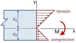
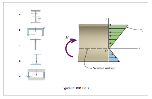
consider a positive bending moment M applied, stresses are positive below N.S. and negative above N.S. the flexure formula gives results in the beam where the stress distribution is not disrupted by irregularities in the shape, or by discontinuous in loading (otherwise, stress concentration occurs).

Gross cross section Fig-4: Bending stress distribution ...
Nov 30, 2021 · Introduction to Low Stress Training (LST) Low Stress Training or LST is like bonsai for cannabis plants. It’s the practice of gently bending stems and tying them in place to drastically change the shape of the plant. This is done to create multiple bud sites, even out the canopy, and overall help you use light more efficiently.

Monochrome, Kingfisher Bridge, River Tyne, Lemington, Newcastle Upon Tyne, Tyne & Wear, England.
bending moment diagram [BMD] and shear force diagram [SFD]. Such graphic representation is useful in determining where the maximum shearing force and bending moment occur, and we need this information to calculate the maximum shear stress and …
![[ND_5562] Fixed End Moment Bending Moment Reaction ...](https://static-resources.imageservice.cloud/1473002/structural-engineering-how-to-determine-fixed-end-moment-in-beam.png)
[ND_5562] Fixed End Moment Bending Moment Reaction ...
2 Stress distribution. 3 Bending stresses. 4 Testing of ductile materials. Stress distribution. The bending load has its highest value in the cross section of the maximum The diagram below shows the corresponding course of the bending moment and the shear force over the entire specimen length.

Stress distribution in I cross section beam | Download ...
• Bending stress in a shallow conical head. Higher stress limits are usually incorporated into the design rules and equations for components that conform to Comparison of bending stress variations during meshing cycle and maximum values of bending stresses are shown in Figure 4 . As illustrated...
Beam Analysis Quick Reference (Formula Sheet) | MechaniCalc
In our previous session, we were discussing the bending stress produced in a beam which is subjected to a pure bending. We can say, from equation of shear stress for a circular section, that shear stress distribution diagram will follow parabolic curve and we have drawn the shear stress...

Strain and stress distribution in singly reinforced ...
I don't have too much information beyond the title. The book didn't have much in the way of text, just a lot of different signs/diagrams of various occult-looking stuff. A big part of its aesthetic was to combine elements of blueprints/industrial design with the occult. EDIT: I'VE FOUND IT https://deepfates.com/writing/2014/10/31/SIGNAL-a-book-of-secrets.html

Unsymmetrical Bending Shear Stress Distribution - [PPT ...
As an example of how the stress-moment relationship is computed using the allowable stress design method, consider a free-body diagram cut from a rectangular cross section of width, b, and height, h (assuming a linear stress-strain relationship resulting in a linear stress diagram), as shown in Figure 8.9a.

Stress distribution in I cross section beam | Download ...
Stresses: Beams in Bending. 241. With this, our stress-strain relations reduce to three equations for the normal strain components in terms of the only significant stress We could, if we wish, at this point use the same free body diagram above to. obtain an expression for the bending moment distribution.

Bending stress distribution of tine with cross-sectional ...
Euler–Bernoulli beam theory (also known as engineer's beam theory or classical beam theory) is a simplification of the linear theory of elasticity which provides a means of calculating the load-carrying and deflection characteristics of beams.

Through thickness distribution of bending stress ( σ x ...
Bending stresses are almost zero except at the fixed edges. A plot of the actual deflection vs the deflection for a true sphere shows that the shape is not truly spherical, which matches the membrane stress plot which shows a non uniform stress distribution.

Monochrome, Scotswood Bridge, Tyne & Wear, England.
In many ways, bending and torsion are pretty similar. Bending results from a couple, or a bending We can look at this stress distribution through the beam's cross section a bit more explicitly These diagrams will be essential for determining the maximum shear force and bending moment along a...

Kingfisher Bridge, Blaydon A1 Bridge & Blaydon Railway Bridge, Newcastle/Gateshead, Tyne & Wear, England.
Shear force and bending moment diagrams tell us about the underlying state of stress in the structure. So naturally they're the starting point in any design So in this post we'll give you a thorough introduction to shear forces, bending moments and how to draw shear and moment diagrams.

Finding Forces on Cantilever Beam - YouTube
Solved: Explain And Show How The Shear Diagram And Moment ...

When we visited Utö, the most outer island of this beautiful archipelago in the place we call Finland, I allowed myself to be guided by the incredible energy of Inca, the daughter of the family we were visiting there. She took me to a series of abandoned bunkers from the times this island was a military strategic point and there I found this graffiti that represent very well the feeling of all that has to do with military, war, conflict and drama. With love from Korpo.

Train Tracks & Overhead Road Bridge, Newcastle/Gateshead, Tyne & Wear, England.

Monochrome, Blaydon Railway Bridge, Tyne & Wear, England.
How can the flexural equation (E/R=M/I=F/Y) give me an ...

Stress-Strain Distribution | Download Scientific Diagram
Solved: The Beam Normal Stress Distribution Shown In Figur ...

How to calculate bending stresses in beam - Engineering Feed


Comments
Post a Comment