40 how to read a pressure enthalpy diagram
From Figure 1-5, 1-7 and Figure 1-8, the enthalpy values of the various points of the refrigeration cycle can be obtained as the following: H 1= 102.42 BTU/LB H 2= 128.00 BTU/LB H 4= 112.31 BTU/LB H 5= 40.85 BTU/LB H 6= 40.85 BTU/LB Reading the liquid-vapor dome section of a pressure-enthalpy diagram. Liquid-Vapor Dome LIQUID VAPOR DOME The shaded dome-like regionoutlines when the compound is both a mix of The tip of the dome marks the critical point. area to the right of the critical point is vapor. The area to the left of the critical point is liquid. The region above is
Jan 07, 2014 · This video explains the parts of a pressure-enthalpy diagram for a single-component system and discusses how enthalpy depends on pressure for water. If these diagrams are a breeze for you, or you're just looking for help with another concept, check out other chemical engineering tutorials in the Learn ChemE Engineering Screencast series .

How to read a pressure enthalpy diagram
Enthalpy [kJ/kg] Pressure [MPa] Methane Pressure-Enthalpy Diagram S=Specific Entropy, kJ/kg*K T=Temperature, ºC T=-160 T=-150 T=-140 T=-130 T=-120 T=-110 T=-100 T=-90 T=-170 T=-100 T=-50 T=0 T=50 T=100 T=150 T=200 Produced by I. Aartun, NTNU 2002. Based on the program Allprops, Center for Applied Thermodynamic Studies, University of Idaho. S ... Pressure-Enthalpy Diagram for R134a Refrigerant How to Read a Pressure-Enthalpy Diagram In chemical engineering, it is often necessary to know how properties like pressure, enthalpy, volume, and entropy relate to each other at a certain temperature. A Pressure-Enthalpy Diagram provides this information but can be cryptic to decipher. What you need to know: Liquid/vapor dome region
How to read a pressure enthalpy diagram. An enthalpy diagram is a method used to keep track of the way energy moves during a reaction over a period of time. Learn how to draw and label enthalpy diagrams, the definition of an enthalpy ... tecquipment.com Pressure-Enthalpy chart, R-134a (1,1,1,2-tetrafluoroethane) Enthalpy (kJ/Kg) Pressure (Bar) Pressure (MPa) Produced by TecQuipment's VDAS ® system Describes how to use an interactive simulation that represents a pressure-enthalpy diagram. The various sets of curves on the diagram (vapor quality, tempera... On the P-H diagram, pressure is indicated on the y-axis and enthalpy is indicated on the x-axis. Typically enthalpy is in units of Btu/lb and pressure is in units of pounds per square inch (psi). The upside down U figure shown on the diagram designates the points at which the refrigerant changes phase.
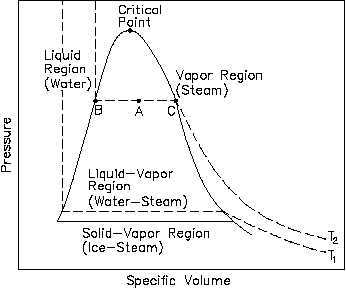
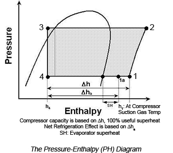
The pressure-enthalpy diagram (log P/h diagram) is a very useful tool for refrigerant technicians. First, an explanation of how the diagram is built up is given, and then its use is describ ed. Figure 2.1 shows the principle of a log P/h diagram, and indicates the refrigerant's various thermodynamic states. A "good" service technician can find the usual problem - it takes a "very good" service technician to find the unusual! Knowing how to construct and interpret a pressure enthalpy (PH chart separates the good technician from the very good service engineer. Figure 1 is a PH diagram for R-22 refrigerant. The pressure-enthalpy chart, as shown in Fig. 2, displays all the pertinent properties for a given refrigerant (in this example R22). The bubble to the left is the portion of the diagram where the refrigerant is in the saturated condition. The blue line on the left of the bubble represents the 100% saturated liquid line, Various refrigerant states identified on a pressure enthalpy chart.Please provide feedback on this module by selecting "Like" or "Dislike". Your feedback and...
This screencast has been updated. Please see the revised version here: https://youtu.be/jGIHNKLMLCY Made by faculty at the University of Colorado Boulder, D... 4.88 pressure-enthalpy diagram for ethylene 10 100 1000 10000 700 750 800 850 900 950 1000 1050 1100 1150 1200 enthalpy, Btu/lb pressure (psia) 160 F 140 F 120 F 100 F 80 F 60 F 40 F 20 F 0 F 20 F 240 F 200 F 100 F 0 F 100 F 200 F 300 F liquid liquid-vapor two phase vapor psia = pounds per square inch absolute R410A Pressure Enthalpy Chart. Scroll down to download a PDF copy of the pressure enthalpy chart for both Metric and Imperial Units. These charts were provided courtesy of Danfoss, using their FREE CoolSelector 2 software. A Mollier diagram(another name for a pressure-enthalpy diagram) locates system operating pres-sures on the vertical (y) axis and enthalpy values on the horizontal (x). Physical properties of the axis refrigerant are represented by a curve that roughly resembles a thumb or a tongue. The curve for R-22, shown in Figure 3 on the next page, begins at a point
"How to be an artist" by Jerry Saltz
HFC-134a Pressure-Enthalpy Diagram (Engineering Units). (4/05) RWJ291 Printed in U.S.A. [Replaces: H-39917] Reorder No.: H-39917-1
Refrigeration: Pt Diagram Refrigeration Cycle
Pressure / Enthalpy Diagram Example. This article was written by my buddy and Canadian Supertech Tim Tanguay. Thanks, Tim! This P/E chart shows R410a at 100°F saturated condensing temp, 10°F SC, 40°F saturated suction temp, 20°F SH at the compressor. The green highlighted thumb shape is the saturation zone.

Refrigeration : how to read and interpret he Pressure ...
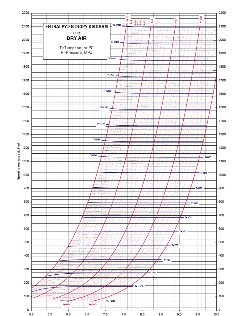
An enthalpy-entropy chart, also known as the H-S chart or Mollier diagram, plots the total heat against entropy, describing the enthalpy of a thermodynamic system. A typical chart covers a pressure range of .01-1000 bar, and temperatures up to 800 degrees Celsius. It shows enthalpy in terms of internal energy, pressure and volume using the relationship = + (or, in terms of specific ...

Enthalpy Charts: What They Can Tell the Technician ...
pressure is read on the vertical scale along the left side. Enthalpy (heat content) is read on the bottom scale at a number of different temperatures. To the right is a curve representing saturated vapor. This is vapor associated with liquid, and the type of vapor found in a refrigerant cylinder, a condenser, or a flooded evaporator.
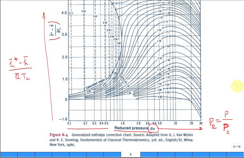
Intro enthalpy departure chart - YouTube
Reading Enthalpy from ln P-H diagram. Since this is a ln Pressure-Enthalpy graph, the enthalpy is marked on the x-axis. Then, a vertical line is a line of constant enthalpy. Previous: Reading Pressure ------- Next: Reading Temperature.

à¸à¸£à¸°à¸šà¸§à¸“à¸à¸²à¸£à¸—างไซโครเมตริà¸à¹à¸¥à¸°ph chart
The Pressure-Enthalpy Diagram is useful tool for refrigerant technicians. It can be seen as a map of the refrigerant. It allows to show, how thermodynamic pr...
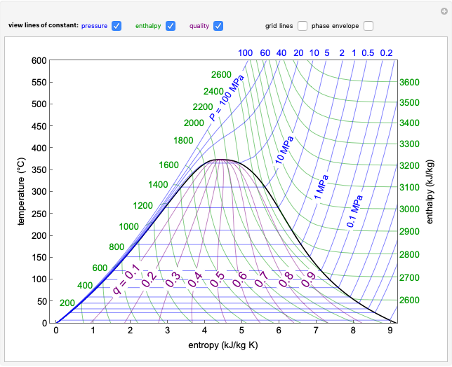
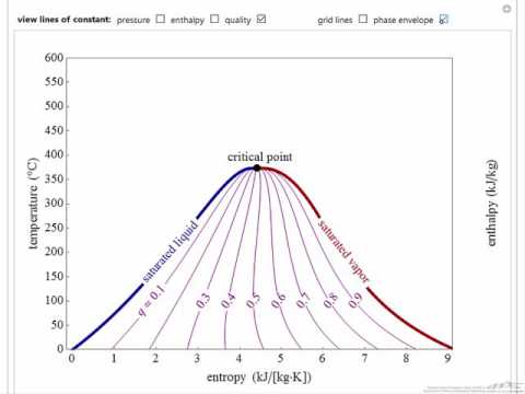
Temperature-Entropy Diagram for Water - Wolfram ...
Carbon Dioxide: Pressure - Enthalpy Diagram Melting Line-40 o -40 C-2 0-2 0. Title: mollier_chart_met.xls Created Date: 11/10/1999 5:42:45 PM

How to read - charts. Why?
The pressure-enthalpy diagram (log P/h diagram) is a very useful tool for refrigerant technicians. The area below the saturation lines for liquid and gas (A-CP-B in Figure 2.1) represents the conditions where the refrigerant can change its state of aggregation from liquid to gas or vice versa.

Chapter 4: The First Law of Thermodynamics for Control ...
The term "Mollier diagram" (named after Richard Mollier, 1863-1935) refers to any diagram that features Enthalpy on one of the coordinates. Commonly used Mollier diagrams are the enthalpy-entropy (or h-s) diagram ( below) and the pressure-enthalpy diagram illustrated at the bottom of this page. The h-s diagram is one in which Enthalpy ...

On the road to where?
this lecture will explain how to use P-H chart for calculating COP, Heat rejected by Condenser, Refrigerating effect, compressor power.

~: July 2013
How to Read a Pressure-Enthalpy Diagram In chemical engineering, it is often necessary to know how properties like pressure, enthalpy, volume, and entropy relate to each other at a certain temperature. A Pressure-Enthalpy Diagram provides this information but can be cryptic to decipher. What you need to know: Liquid/vapor dome region
Pressure-Specific Volume (P-n) Diagram
Pressure-Enthalpy Diagram for R134a Refrigerant

How To Read A Mollier Diagram
Enthalpy [kJ/kg] Pressure [MPa] Methane Pressure-Enthalpy Diagram S=Specific Entropy, kJ/kg*K T=Temperature, ºC T=-160 T=-150 T=-140 T=-130 T=-120 T=-110 T=-100 T=-90 T=-170 T=-100 T=-50 T=0 T=50 T=100 T=150 T=200 Produced by I. Aartun, NTNU 2002. Based on the program Allprops, Center for Applied Thermodynamic Studies, University of Idaho. S ...
Refrigeration: Refrigeration Ph Chart
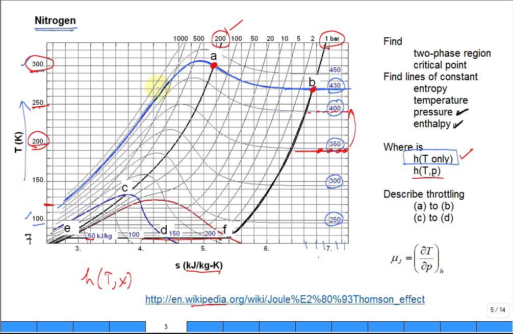
Explain Joule Thomson effect with Nitrogen TS diagram ...
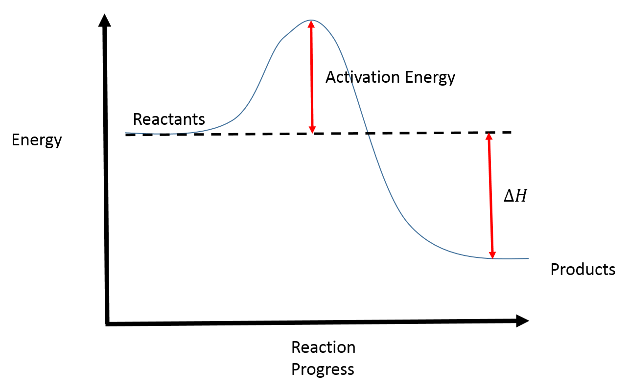
Reaction Coordinate Diagrams - College Chemistry
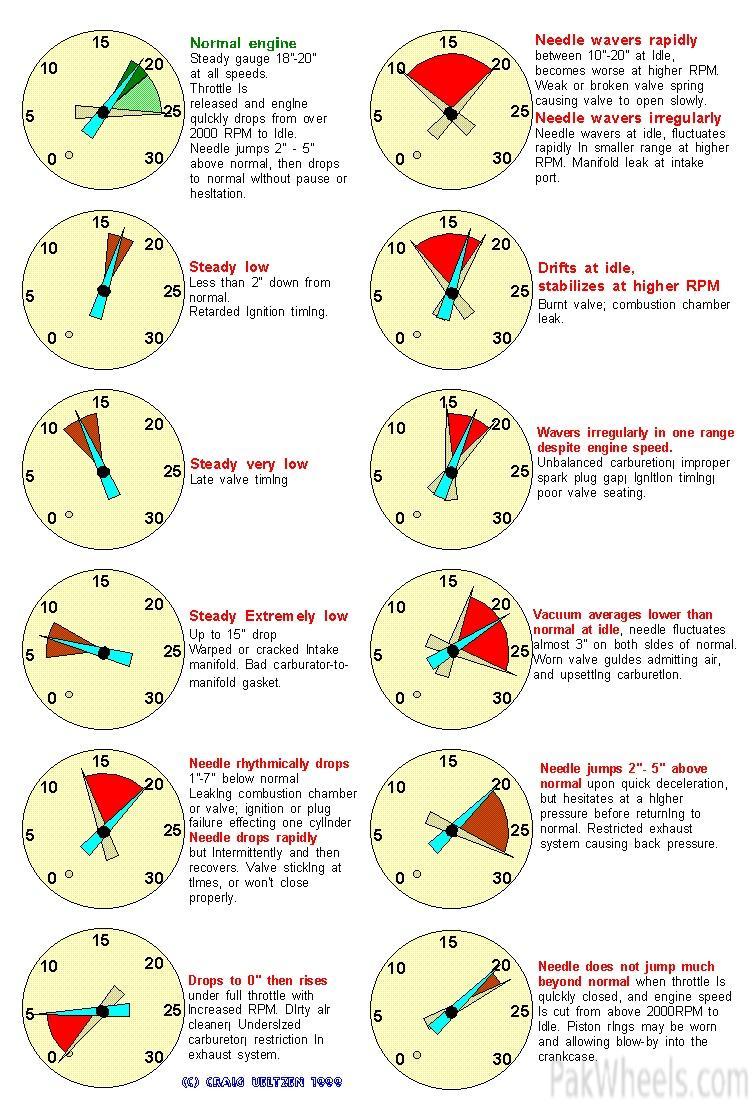
How do I use a vacuum pump to diagnose rough idle? - Jeep ...

Walid Chakroun - ASHRAE - REFRIGERANTI E LORO USO RESPONSABILE
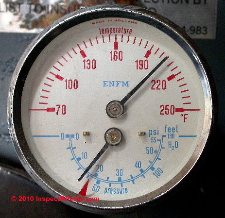
Boiler Gauges, how to read the temperature & pressure ...

Temperature-Entropy Diagram for Water - Wolfram ...

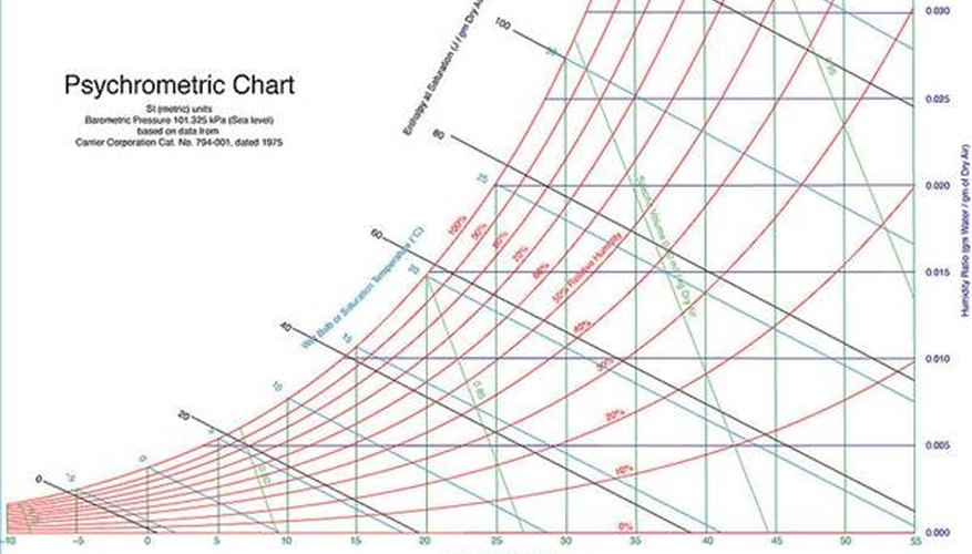
How to Read a Psychrometric Chart - Engineering Success

Antenatal Care Module: 9. General Assessment of the ...
Why do I care about phase diagrams? | Campbell Tip of the ...

Chapter 10b: The Psychrometric Chart (Updated 7/22/2014)
How to Read a Sling Psychrometer | Sciencing

The Refrigeration Cycle

Mollier chart for steam pdf casaruraldavina.com

Mallard

MATLAB program for plotting a Simplified Psychrometric ...
How to read a Mollier Diagram | Doovi

Refrigeration: Cop Refrigeration Values

Young man who loves to read

How to Use a Refrigerant Gauge Set STEP BY STEP to Read ...
Refrigeration: Refrigeration Ph Cycle
Reading Entropy from ln P-H diagram

Txy and Pxy diagram

Refrigeration: Refrigeration Psychrometric Chart

How to read pressure enthalpy diagram (lgp-h) - YouTube

Quiz & Worksheet - Drawing & Labeling Enthalpy Diagrams ...
Enthalpy-Entropy Diagram (Air) | Enthalpy | Statistical ...


Comments
Post a Comment