40 iron carbon phase diagram explanation
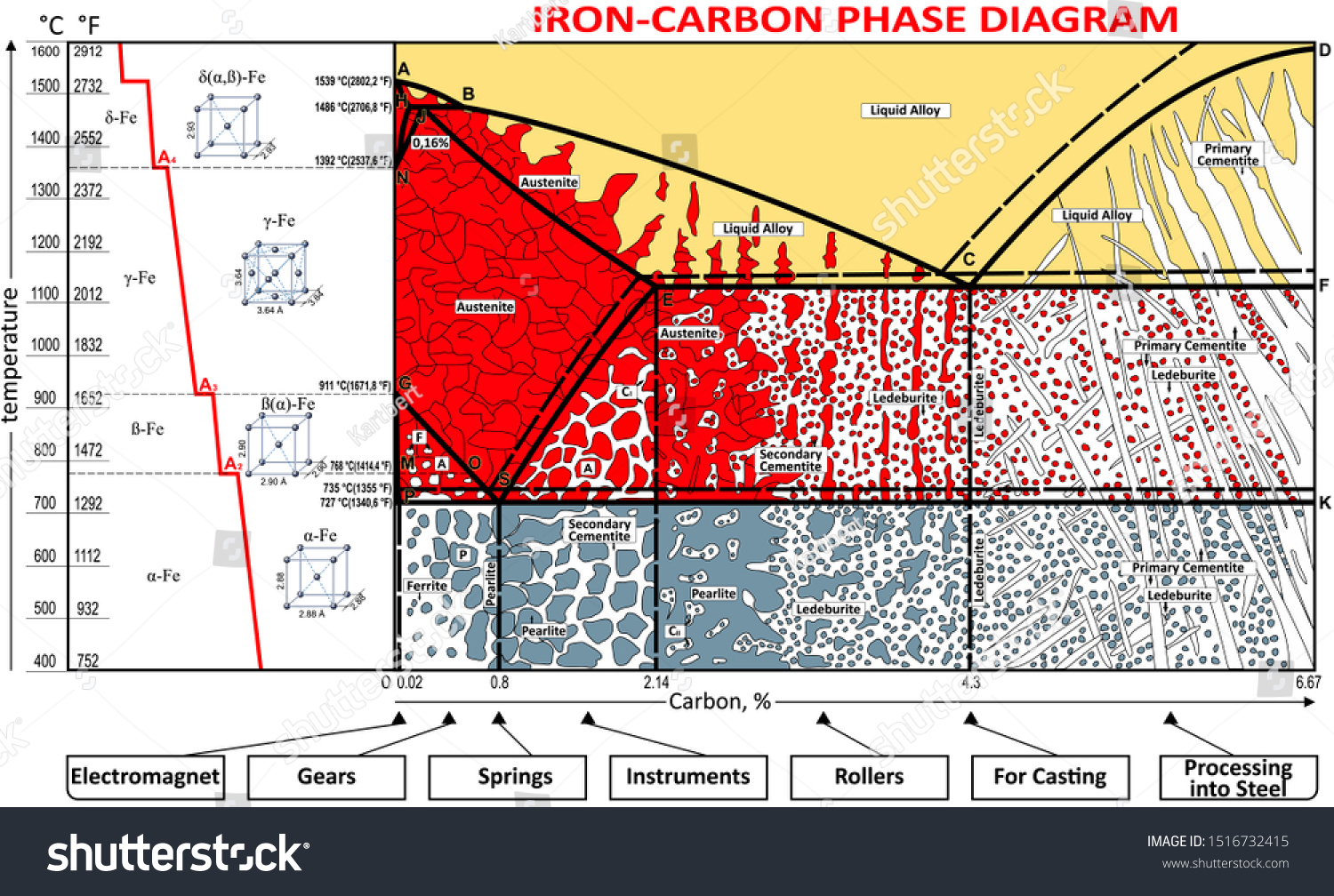
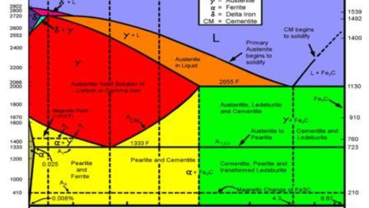
An iron-carbon phase diagram represents the relationship between temperatures, compositions, and crystal structures of all phases that may be formed by iron and carbon. Thus, it is felt some knowledge of the iron-carbon phase diagram is helpful for better understanding of gear heat treatment. This iron carbon phase diagram is plotted with the carbon concentrations by weight on the X-axis and the temperature scale on the Y-axis. Iron crystal structures explained The carbon in iron is an interstitial impurity. The alloy may form a face centred cubic (FCC) lattice or a body centred cubic (BCC) lattice.
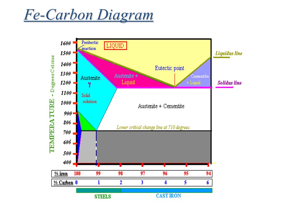
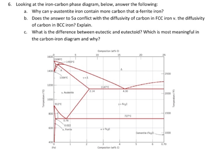
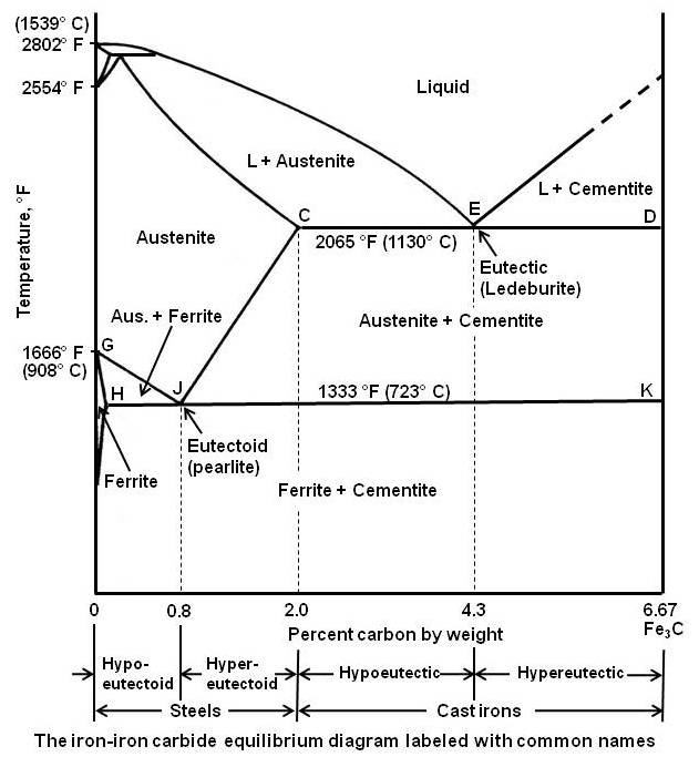
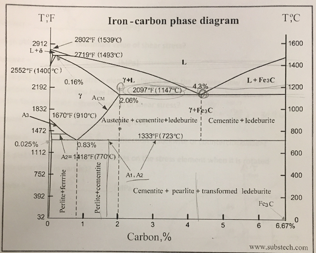
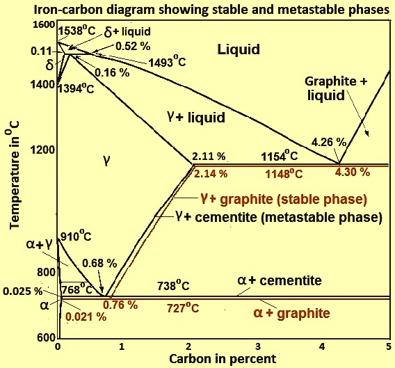
Iron-Carbon Phase Diagram with Detailed Explanation: If the percentage of the carbon is in the range of 0 to 2.11 % then it is called Steel and if the percentage of carbon is in the range of 2.11 to 6.67% then it is called Cast iron. As the carbon content increases, it produces more Iron-Carbide volume and that phase will exhibit high hardness.

Iron carbon phase diagram explanation
Examples of Type IV Adsorption Isotherm are of adsorption of Benzene on Iron Oxide (Fe 2 O 3) at 500°C and adsorption of Benzene on silica gel at 500°C. Type V Adsorption Isotherm: Type V Adsorption Isotherm . Explanation of Type V graph is similar to Type IV. Example of Type V Adsorption Isotherm is adsorption of Water (vapors) at 1000°C on ... 22/04/2011 · The approach uses polyaniline as a precursor to a carbon-nitrogen template for high-temperature synthesis of catalysts incorporating iron and cobalt. The most active materials in the group catalyze the ORR at potentials within ~60 millivolts of that delivered by state-of-the-art carbon-supported platinum, combining their high activity with remarkable performance … The Iron-Carbon Diagram: A map of the temperature at which different phase changes occur on very slow heating and cooling in relation to Carbon, is called Iron- Carbon Diagram. Iron- Carbon diagram shows - the type of alloys formed under very slow cooling, proper heat-treatment temperature and
Iron carbon phase diagram explanation. 13/08/2014 · $\begingroup$ This could really do with some explanation of the Clapeyron ... If it is decreasing, the liquid phase is denser, if it is increasing, the solid phase is denser. For example, the phase diagram of water has a negative solid-liquid line; the liquid phase of water is denser. The densest phase exists at the highest pressure and lowest temperature. This comes back to … The Iron carbon equilibrium diagram (also called the iron carbon phase diagram) is a graphic representation of the respective microstructure states of the alloy iron – carbon (Fe-C) depending on temperature and carbon content. The iron carbon phase diagram is commonly used to fully understand the various phases of steel and cast iron. The Iron-carbon phase or equilibrium diagram is an overall study of iron, carbon, and their alloys and how they act under the various equilibrium conditions. In this blog, we studied these aspects of the equilibrium diagram and also how phase transformation depends upon the temperature conditions. Although it is known as an equilibrium diagram ... 42 iron carbon phase diagram explanation. Hypereutectoid steel: has a carbon content greater than the eutectoid 8 Example: Phase Equilibria For a 99.6 wt% Fe-0.40 wt% C at a temperature just below the eutectoid, determine the following a) composition of Fe 3C and ferrite (α) b) the amount of carbide (cementite) in grams that forms per 100 g of ...
Explanation: A phase diagram is a graphical representation of the phases present in the system of materials at various temperatures, pressures, and compositions. These diagrams show the constitution of alloys as a function of temperature under equilibrium conditions. They are otherwise also known as equilibrium or constitutional diagrams. 01/08/2014 · Phase change materials (PCMs) used for the storage of thermal energy as sensible and latent heat are an important class of modern materials which substantially contribute to the efficient use and conservation of waste heat and solar energy. The storage of latent heat provides a greater density of energy storage with a smaller temperature difference between storing and … Iron/Carbon Phase Diagram Iron shows a eutectic with Carbon allowing for a lower melting alloy Body Centered Tetragonal. 6. 7. 8 Carbon content can be reduced by reaction with oxygen and stirring. 9. 10 Eutectoid Steel Pearlite. 11 Time-Temperature-Transformation Diagram. 12 Time-Temperature-Transformation Diagram https://goo.gl/nMe9J1 For 60+ videos on Engineering Materials
Water has a very high specific heat capacity of 4184 J/(kg·K) at 25 °C – the second-highest among all the heteroatomic species (after ammonia), as well as a high heat of vaporization (40.65 kJ/mol or 2257 kJ/kg at the normal boiling point), both of which are a result of the extensive hydrogen bonding between its molecules. These two unusual properties allow water to … Carbon capture and storage (CCS) is recognised as being vital to least cost pathways for climate change mitigation, and in particular the negative emissions technologies (NETs) that are key to limiting warming to “well below” 2C. However, it has not yet been deployed on the scale understood to be required, owing to a variety of technical, economic and commercial … In physics, a state of matter is one of the distinct forms in which matter can exist. Four states of matter are observable in everyday life: solid, liquid, gas, and plasma.Many intermediate states are known to exist, such as liquid crystal, and some states only exist under extreme conditions, such as Bose–Einstein condensates, neutron-degenerate matter, and quark–gluon plasma, which … Click here to download pdf notes NOW - http://bit.ly/3lggovpIron Carbon DiagramIron Iron Carbide DiagramIron Carbon Phase Diagram ExplanationIron Carbon Equ...
Iron –carbon phase diagram
Fig. 5 demonstrates the calculated Fe–C phase diagram under 0 and 10 T together with experimental data , including the compositions of target alloys also. It can be seen that samples Fe–0.4 wt%C and Fe–0.6 wt%C are located in (α+γ) two-phase region. It is indicated that the magnetic field alters volume fractions of the phases according ...

Mod-01 Lec-23 Iron-Carbon Phase Diagram - YouTube
The Iron-Carbon Diagram: A map of the temperature at which different phase changes occur on very slow heating and cooling in relation to Carbon, is called Iron- Carbon Diagram. Iron- Carbon diagram shows - the type of alloys formed under very slow cooling, proper heat-treatment temperature and
Coloring Vector Ironcarbon Phase Diagram Stock Vector ...
22/04/2011 · The approach uses polyaniline as a precursor to a carbon-nitrogen template for high-temperature synthesis of catalysts incorporating iron and cobalt. The most active materials in the group catalyze the ORR at potentials within ~60 millivolts of that delivered by state-of-the-art carbon-supported platinum, combining their high activity with remarkable performance …

Compute: a) the mass fractions of proeutectoid ferrite, and b ...
Examples of Type IV Adsorption Isotherm are of adsorption of Benzene on Iron Oxide (Fe 2 O 3) at 500°C and adsorption of Benzene on silica gel at 500°C. Type V Adsorption Isotherm: Type V Adsorption Isotherm . Explanation of Type V graph is similar to Type IV. Example of Type V Adsorption Isotherm is adsorption of Water (vapors) at 1000°C on ...
![Iron-Carbon Diagram Explanation [PDF]](https://mechanicalenotes.com/wp-content/uploads/2018/10/Iron-Carbon-Phase-diagram-feature-image.png)
Iron-Carbon Diagram Explanation [PDF]

The Iron Carbon Phase Diagram
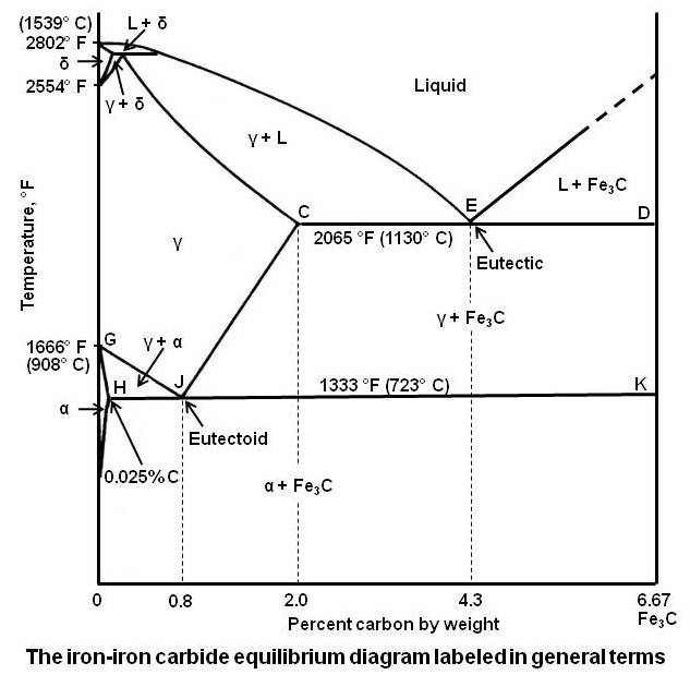
Practical Maintenance » Blog Archive » The Iron-Iron Carbide ...
![Iron-Carbon Phase Diagram Explained [with Graphs]](https://fractory.com/wp-content/uploads/2020/03/Iron-carbon-phase-diagram-explained.jpg)
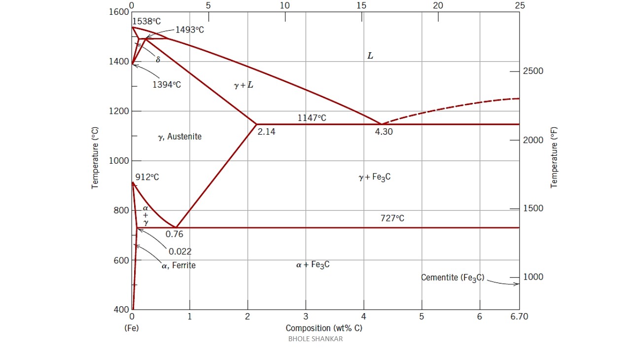
Iron-Carbon Phase Diagram Explained [with Graphs]
![Iron-Carbon Phase Diagram Explained [with Graphs]](https://fractory.com/wp-content/uploads/2020/03/Phase-diagram-of-steel-and-cast-iron.jpg.webp)
Iron-Carbon Phase Diagram Explained [with Graphs]
phase diagram iron carbon | Metallurgy for Dummies
Introduction to Iron Carbon Phase Diagram | Engineering Materials
Fe-Carbon Phase Diagram - ppt video online download

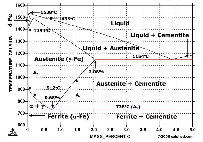
Delta Iron - an overview | ScienceDirect Topics
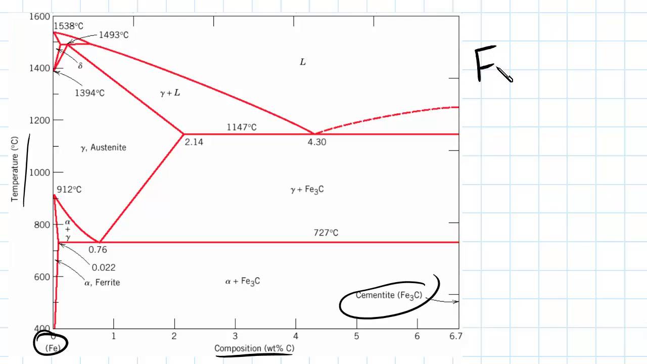
The Iron - Iron Carbide (Fe-Fe C) Phase Diagram
Solved Looking at the iron-carbon phase diagram, below ...

Lecture 7 - Steel & Cast Irons Flashcards | Quizlet

Iron-Carbon Phase Diagram (a review) see Callister Chapter 9 ...

Iron-Carbon Diagram - UK | PDF | Annealing (Metallurgy) | Steel
![Iron-Carbon Diagram Explanation [PDF]](https://mechanicalenotes.com/wp-content/uploads/2020/05/alpha-iron.jpg)
Iron-Carbon Diagram Explanation [PDF]

Can Someone Explain Me About This Iron - Carbon Phase Diagram ...

Delta Iron - an overview | ScienceDirect Topics
Practical Maintenance » Blog Archive » The Iron-Iron Carbide ...

Iron-carbon phase diagram | Value Creation from Uzbekistan
Solved TF Iron - carbon phase diagram TC 2912 2802°F (15390 ...

Iron carbon equilibrium diagram with explanation. ||Engineer's Academy||
IRON –CARBON PHASE DIAGRAM
The Iron-Carbon Phase Diagram – IspatGuru
Iron Carbon Phase or Equilibrium Diagram or Iron Carbide ...

Pearlite - Wikipedia
carbon: iron-carbon equilibrium diagram - Students ...

TPCE Mech Books: IRON CARBON Phase Diagram or Equilibrium Diagram

4 Iron-Carbon phase diagram | Download Scientific Diagram

Phase (matter) - Wikipedia
The Iron - Iron Carbide (Fe-Fe C) Phase Diagram
![Iron-Carbon Phase Diagram Explained [with Graphs]](https://fractory.com/wp-content/uploads/2020/03/Phase-diagram-of-steel-and-cast-iron.jpg)
Iron-Carbon Phase Diagram Explained [with Graphs]
iron carbon phase diagram — Steemit

Phase Diagram - Industrial Metallurgists

What is the carbon concentration of an iron-carbon alloy for ...
IRON-CARBON EQUILIBRIUM DIAGRAM | Engineers Gallery
The C-Fe (carbon-iron) system


Comments
Post a Comment