41 bennett trim tab wiring diagram
Bennett Trim Tabs Wiring Diagrams | Manual E-Books – Bennett Trim Tab Wiring Diagram Wiring Diagram contains several comprehensive illustrations that show the relationship of assorted products. It contains guidelines and diagrams for different kinds of wiring techniques and other things like lights, windows, and so forth. Wiring Diagram Installation Instructions Twisted Extension Cable (Variable Length) ... The port trim tab lowers the starboard side bow, and the ... side bow. Properly sized trim tabs improve the performance of your boat by adjusting the running angle of your vessel. Bennett Marine trim tabs help you get on plane faster, correct listing, improve ...
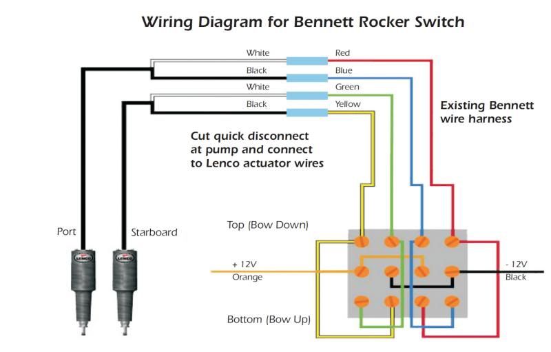
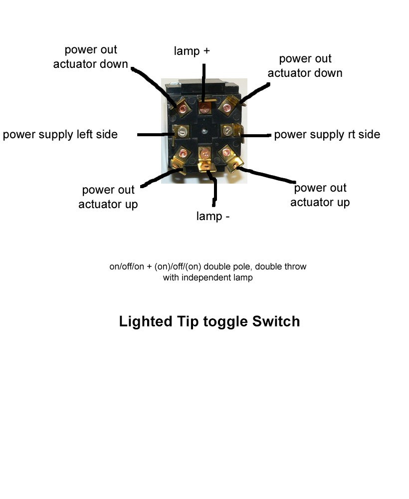
Bennett H Pipe Nipple 75mm (3-inch) . EIC Wiring Harness. Bent Trim Tabs Wiring Diagram Page 2 And Rhrivcasorg: Bennett Trim Tab Switch Lenco Trim Tab Switch Wiring Diagram Testing A Bent V Rhphiltegin. The helm control is wired so that all you have to do is press Bennett Trim Tabs becomes second nature after a short time. Superior . Diagram #.

Bennett trim tab wiring diagram
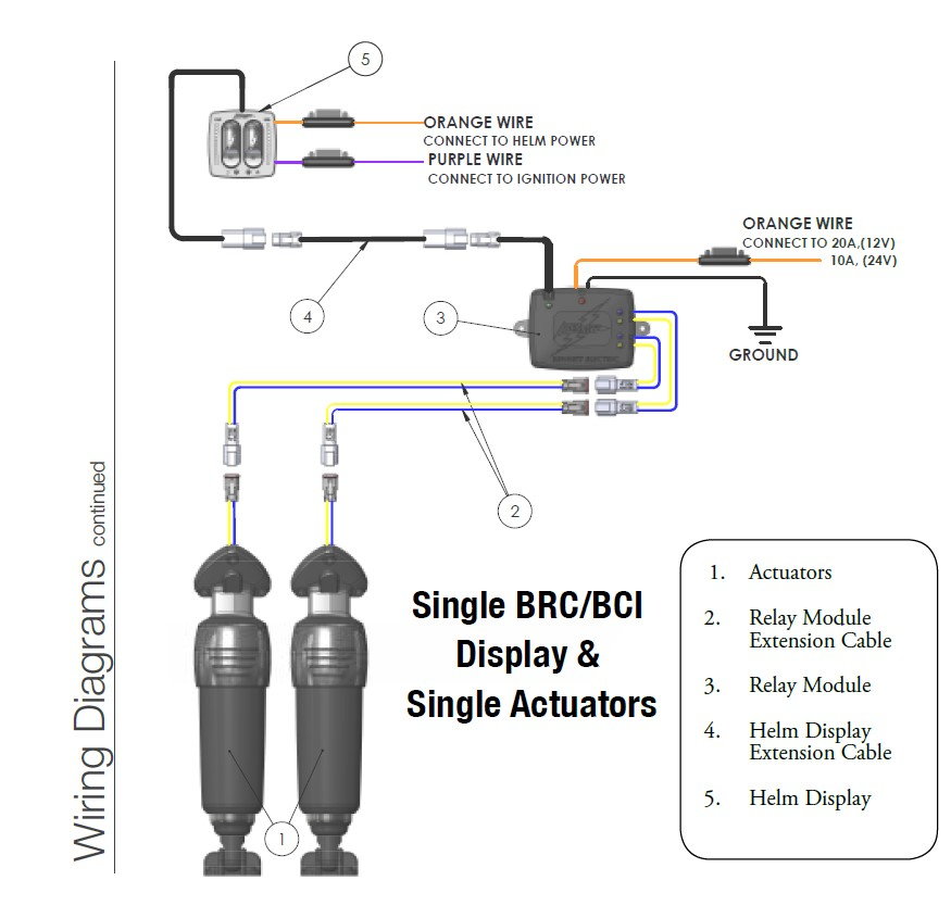
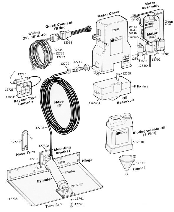
Bennett offers this 22' harness as a solution to connect the control switch to the hydraulic power unit. Key Features 22' wiring harness to connect Bennett trim tab control switches to hydraulic power unit. Wiring diagram for Bennett Trim Tabs using a Carling VLD1 Rocker Switches Navigation Light wiring using LT and LT Switch Operation. The BXT trim tabs may be operated individually so that you can correct for a “listing” ... the wires and the hydraulic ports face away from the transom.16 pages How Trim TaBs work Bennett Trim Tabs are attached to the bottom edge of the transom. When the helm control is pressed, the trim tabs move into position. Water-force on the trim tab surface creates upward pressure, raising the stern and lowering the bow. Properly sized trim tabs improve the performance of your boat in a wide
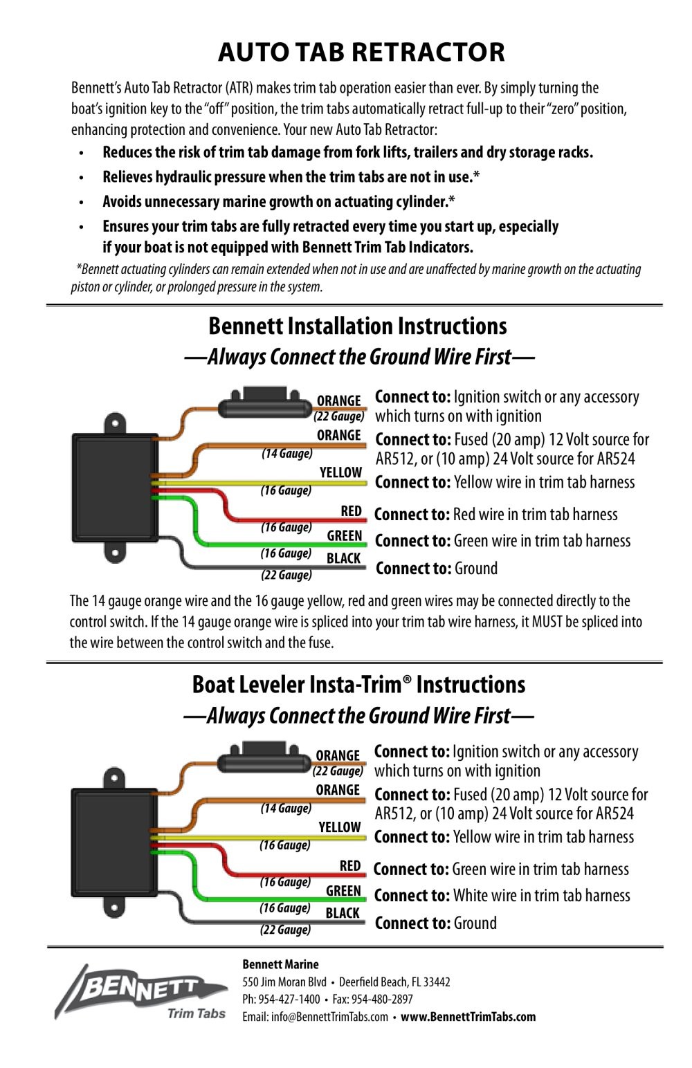
Bennett trim tab wiring diagram. 2.5" Hole saw. Wiring Diagram. Have questions? We're here to help. Visit BennettTrimTabs.com or call (954)427-1400. Installation Instructions.2 pages Bennett Hydraulic Trim Tab Wiring Diagram – wiring diagram is a simplified normal pictorial representation of an electrical circuit. It shows the components of the circuit as simplified shapes, and the facility and signal links amongst the devices. Maximize Performance While Smoothing Out The Ride: Bennett trim tabs enhance the operating economy of ... System Wiring Diagrams & Installation Templates . Please refer to the system diagram on page 13 for detailed system wiring requirements. For detailed information on actuators, trim tabs, ...48 pages
sensor wires. You will do this for each side of the boat: 1. Each trim tab is installed as an extension of the hull. To achieve.16 pages performance with Bennett’s BOLT Electric trim tab systems. BOLT systems feature an innovative actuator seal design built to outlast any electric trim tab system on the market. Kits Include: • (2) 12-volt fixed upper ... Electric Trim Tab System Common Wiring Diagrams BOLT. Congratulations, you are the owner of the finest trim tabs available. ... Product Catalog — with featured accessories and an interactive parts diagram.12 pages Bennett Electric Trim Tab Wiring Diagram – wiring diagram is a simplified gratifying pictorial representation of an electrical circuit. It shows the components of the circuit as simplified shapes, and the facility and signal friends in the midst of the devices.
DescriptionPART#Available Resour...Actuator Upper Hinge (Hydraulic)A1103Replacing Upper...Auto Tab Control (Hydraulic)AC3000, AC3000A, AC3EIC, AC3EICAInstall Instruction...Auto Tab RetractorAR512, AR524Install InstructionsView 42 more rows 6 Bennett Marine | Bolt Electric Trim Tab System How Trim Tabs Work Bennett trim tabs most often attach to the bottom edge of the transom (although other mounting variations are available). When the helm control is pressed, the trim tabs move up or down. Water-force on the trim tab creates an upward pressure, raising the stern and lowering the bow. Blue – Pump pressure (trim tabs down) Yellow – Pump retract (trim tabs up) Red – Port valve . Green – Starboard valve . Orange with 20 Amp Fuse – 12 volts positive . The above wiring is recommended. If the operator prefers different action from the control and tabs, it can be changed as desired. Bennett Marine . 550 Jim Moran Blvd. How Trim TaBs work Bennett Trim Tabs are attached to the bottom edge of the transom. When the helm control is pressed, the trim tabs move into position. Water-force on the trim tab surface creates upward pressure, raising the stern and lowering the bow. Properly sized trim tabs improve the performance of your boat in a wide
Bennett Electric Trim Tab Wiring Diagram - easywiring
The BXT trim tabs may be operated individually so that you can correct for a “listing” ... the wires and the hydraulic ports face away from the transom.16 pages
Bennett Bolt Extension Cables - The Hull Truth - Boating ...
Bennett offers this 22' harness as a solution to connect the control switch to the hydraulic power unit. Key Features 22' wiring harness to connect Bennett trim tab control switches to hydraulic power unit. Wiring diagram for Bennett Trim Tabs using a Carling VLD1 Rocker Switches Navigation Light wiring using LT and LT Switch Operation.
What does the lenco control box do? - The Hull Truth ...
Bennett Trim Tab Wiring Diagram | Wiring Diagram
![[DIAGRAM in Pictures Database] Nfs 320 Wiring Diagram Just ...](https://cimg2.ibsrv.net/gimg/www.thehulltruth.com-vbulletin/1271x953/lenco_6079022b5cbaf317db85f499af320bdf917e4e7a.jpg)
[DIAGRAM in Pictures Database] Nfs 320 Wiring Diagram Just ...

32 Bennett Trim Tab Wiring Diagram - Worksheet Cloud

Carling Rocker switches

Bennett Trim Tab Wiring Diagram - Free Wiring Diagram

Bennett Trim Tab Wiring Diagram - easywiring
Lenco Trim Tab Switch Wiring Diagram - Wiring Diagram Schemas

Bennett Trim Tab Wiring Diagram - Starlynn News

Need wiring diagram for a boat leveler trim tabs.
Bennett Trim Tab Switch Wiring Diagram - Diagram For You
Bennett Trim Tab rocker switch indicator - The Hull Truth ...
Bennett AutoTrim Pro coming? - Page 6 - The Hull Truth ...
Bennett Trim Tab Wiring Diagram | Manual E-Books - Bennett ...
Lenco Trim Tab Switch Wiring Diagram - Wiring Diagram Schemas

Bennett Hydraulic Trim Tab Wiring Diagram Collection
32 Bennett Trim Tab Wiring Diagram - Wiring Diagram Database

Bennett Trim Tab Wiring Diagram
Bennett Trim Tab Wiring Diagram | Wiring Diagram

Bennett Trim Tab Wiring Diagram - easywiring

Bennett Electric Trim Tab Wiring Diagram - easywiring

Bennett Trim Tab Rocker Switch Wiring Diagram
Lenco Trim Tab Switch Wiring Diagram - Wiring Diagram Schemas

Lenco Trim Tabs Wiring Diagram | Fuse Box And Wiring Diagram
What does the lenco control box do? - The Hull Truth ...

Hey Tabman, need help - The Hull Truth - Boating and ...
![[DIAGRAM] Lenco Trim Tab Wiring Diagram FULL Version HD ...](https://diagramweb.net/img/bennett-trim-tab-rocker-switch-wiring-diagram-9.jpg)
[DIAGRAM] Lenco Trim Tab Wiring Diagram FULL Version HD ...

Bennett Trim Tab Wiring Diagram | Wiring Diagram
Bennett V351 Wiring Diagram
Bennett Trim Tabs Wiring Diagrams | Manual E-Books ...
Boat leveler trim tab works only when both switches are ...
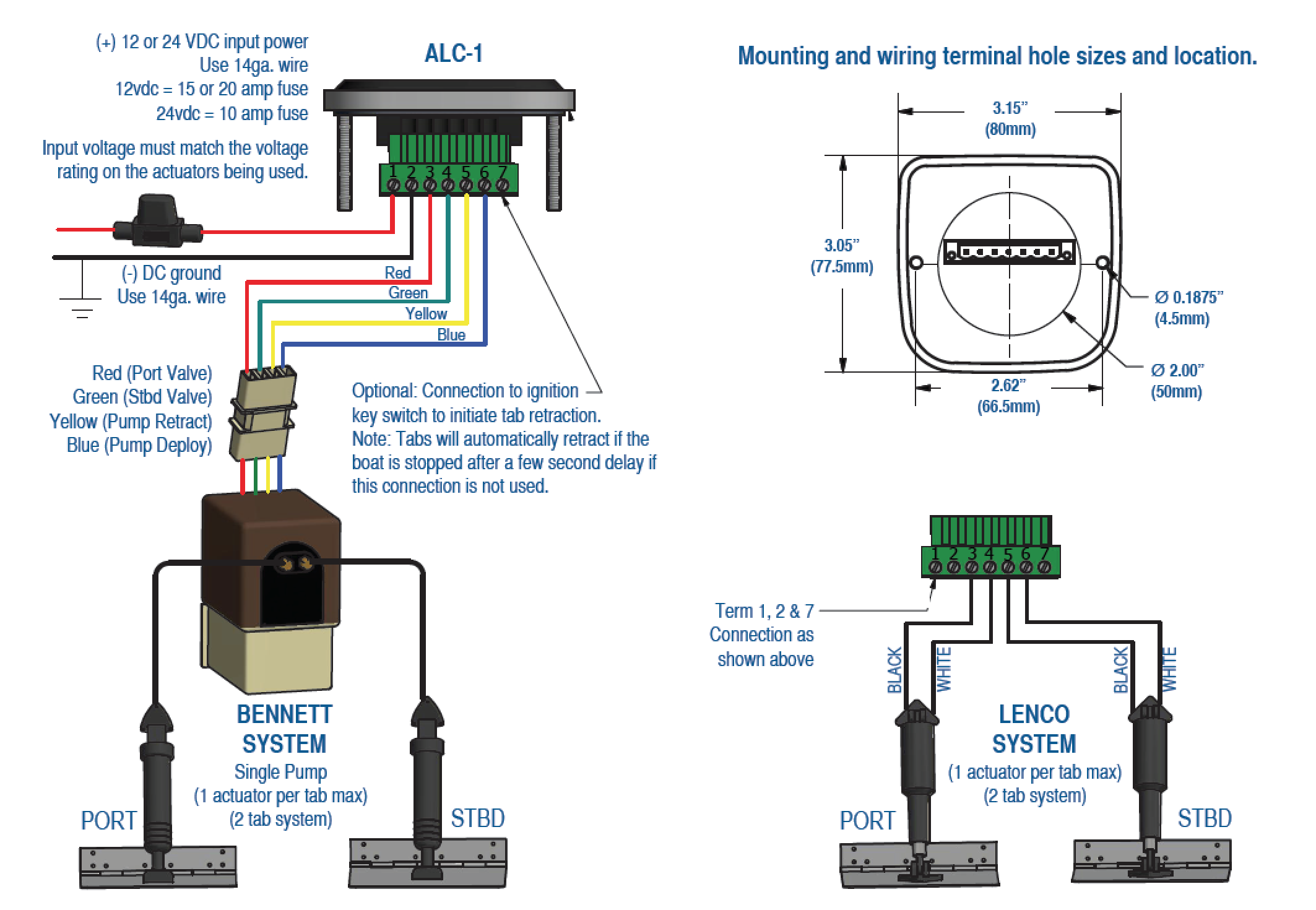
Automatic Level Control For Lenco and Bennett - Products ...
Bennett Hydraulic Trim Tab Wiring Diagram - WEEINKLING

Need wiring diagram for a boat leveler trim tabs.

Bennett Trim Tab Wiring Diagram - easywiring

Bennett Trim Tab Switch Wiring Diagram - Free Wiring Diagram
Bennett Hydraulic Trim Tab Wiring Diagram - Hanenhuusholli

Bennett Trim Tab Switch Wiring Diagram - Wiring Site Resource

Bennett V351 Wiring Diagram


Comments
Post a Comment