42 electric duct heater wiring diagram
Custom built Model CBK electric duct heaters are available for units with accessories not furnished on Stock-Line electric duct heaters. (Consult representative for price and delivery information). DUCT SIZE LIMITS DIMENSIONS 4.8 240 20.0 4.4 230 19.1 4.0 220 18.3 3.6 208 17.3 5.0 240 12.1 4.6 230 11.5 4.1 220 10.9 3.7 208 10.4 catalog 06 electric duct heaters ul & csa listed electric duct heaters stock- line series • quicksilver series • custom built series warren t e c h n o l o g y , i n c 2050 west 73 street hialeah, fl 33016 • telephone: (305) 556-6933 • fax: (305) 557-6157
Duct Heaters • 00.DMP.NB006 R1 4-2019 Why Would I Choose Greenheck Duct Heaters? • The IDHE series is approved by UL for multiple mounting positions • Hinged access cover with latch • All limit controls are resettable • Proven wire rack system that provides very low pressure drop and extended element life
Electric duct heater wiring diagram
A duct heater must be installed according to the installations instructions, wiring diagram and labeling supplied with the heater. Listed below are some important items when installing an electric duct heater: 1. Never operate a duct heater without airflow. The heater must always be interlocked with the fan. This may be accomplished by either an • DHRS •Slip-in Electric Duct Heater • DHRF Flanged Electric Duct Heater • DHRR Round Electric Duct Heater Duct Size • W x H (Specify) Airflow/Overhang • Horizontal/Left (standard) (default) • Horizontal/Right • Horizontal Bottom Mount (Centered) • Vertical/Panel Down • Vertical/Panel Up Line Voltage/Phase • 120V/1 ph. These duct heaters are not intended for installation in series in the air- stream; the heaters are designed for use only as a single unit within a duct ... Follow the wiring diagram on the inside of the terminal box. 15. ... National Electric Code for 75 °C copper wire with not more than 3 conductors in a raceway. The amperages shown are for ...
Electric duct heater wiring diagram. Duct Heaters. 227 Series IOM. Electric Duct Heater Owner's Manual. Instructions for Electric Duct Heaters with Type 3R Terminal Boxes. User Manual - Process Air Heaters. Instructions for Field Replacement of Resistance Open Coil Elements in Brasch Duct Heaters. Unit Heaters. 233 Series IOM. 233 Series Core Replacement. 233 Series Pole ... TUTCO Inc. "E" Series Electric Single Duct VAV / Duct Heater Installation Instructions Heater Models EVH, ERH, EDH & RHE General for All Models Inspect heater for any possible damage. Check all insulators for breakage and inspect heater element wire(s) for any deformation or damage that could cause a short circuit to ground. Jun 16, 2019 · ELECTRIC DUCT HEATER Wiring Diagrams All wiring diagrams shown are for standard heaters up to 2 stages. However a special wiring diagram for heaters above 2 stages or containing optional components is furnished with each heater. National Electrical Code to eliminate shock hazard. Ambient temperatures must be considered when selecting wiring materials for electric heater circuits. Heating equipment and pro-cesses may cause associated wiring to operate well above ambient temperatures. These temperatures may result from heat conducted from the heater terminals, radiation from
per the wiring diagram. 4. Make sure line and control voltage of system matches that noted on wiring diagram. 5. Wire in accordance with N.E.C. and any existing local codes. 6. Check tightness of all factory and field electrical con-nections. 7. If the heater does not have an air flow switch, please make sure a fan interlock is wired. 8. Use ... 2 - Electrical Installation of THERMOLEC heaters. 2.1 Disconnect all power sources before opening the control box and working within. 2.2 Read the nameplate carefully and consult wiring diagram before starting to wire. 2.3 Supply wires: Use only wires suitable for 75°C. Wires shall be sized according to the Canadian Electrical Code requirements. Electric Duct Heaters. Open coil heaters. Installation Instructions (47.66kb) Download document Tubular element heaters. Installation Instructions (47.66kb) Download document Thermo-Air. Instruction Manual (66.13kb) Download document ... Looking for a replacement part? Please utilize the brand specific parts books below, that contain part numbers for replacement parts for MEP products. To order part (s) contact your local electrical/mechanical distributor or our National Parts Supplier, Carroll Parts. Carroll Parts Phone: 800-654-3545 info@carrollparts.com
May 12, 2018 · A wiring diagram is an easy visual depiction of the physical connections as well as physical format of an electrical system or circuit. It demonstrates how the electric cables are adjoined and also can also reveal where components as well as parts could be attached to.Warren Technology CBK Custom Built Electric Duct Heaters for Commercial HVAC SystemsWarren Duct Heater Cbk Wiring Diagram Collection | Wiring Diagram Sample Heater Selection - This diagram shows typical information that you will need when selecting a duct heater. Pilot Light Pilot lights are installed on the side panel and used to indicate heater conditions as follows: - heater energized - step energized - airflow switch open • Available with 24V or 120V control voltages Time Delay Relay or greater as defined on the wiring diagram. Use aluminum wire only when specifically called for on accompanying wiring diagram. 16. If supply connections are for 250 volts or greater, all wiring must be . insulated for 600 volts. 17. When making line connections to heater element terminals FOR FINNED TUBULAR DUCT HEATERS ONLY, apply a wrench ... Figure 1C SLIP-IN HEATER Step 1. Cut hole in side of duct 1/8" larger than heater body. Step 2. Insert heater until terminal box covers opening. Step 3. Secure heater in place with sheet metal screws. Figure 2C FLANGED HEATER Step 1. Provide flanges on ends of duct matching heater flanges Step 2. Secure heater flanges to duct flanges with sheet metal screws,
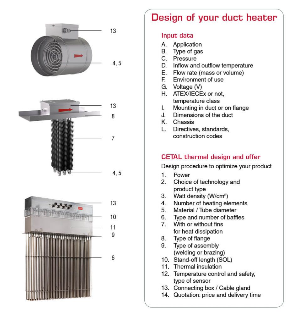
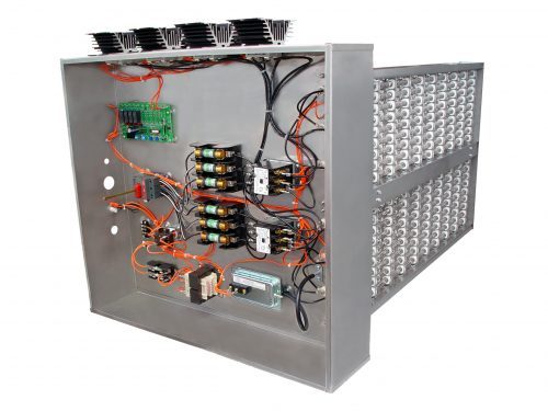
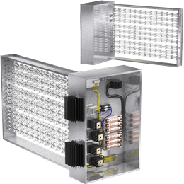
Customized duct heaters - Cetal
Integral electric coils are available on Titus single duct and fan powered terminals. The heater design minimizes stratification and hot spots that can cause nuisance tripping of the thermal cutouts. Each complete terminal, with electric coil installed, is ETL listed and has been tested in accordance with UL standards.

ELECTRIC DUCT HEATERS - PDF Free Download
of open coil and finned tubular duct heaters within minutes. With this software, your local INDEECO representative becomes the source for certified prints, wiring diagrams — complete submittal information. Our heaters and controls range from the simplest standard duct heater to the most sophisticated, custom designed comprehensive system.
Custom Built Electric Duct Heaters – Warren HVAC
fig. 4 - 15kw electric duct heater wiring diagram fig. 5 - 20kw electric duct heater wiring diagram 260 north elm street westfield, ma 01085 (413) 568-9571 • fax (413) 568-9613 7555 tranmere drive mississauga, ontario l5s 1l4 canada (905) 670-5888 • fax (905) 670-5782 fig. 3 - 10kw electric duct heater wiring diagram

QUA & QUZ Standard Open Coil Duct Heaters | Indeeco
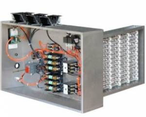
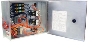
ElEctric coils priceindustries.com | ELEctrIc coILs - Manual 3 iNstAllAtioN AND MoUNtiNG iNstrUctioNs Heater control Panel The heater control panel houses all elements that are required to power up your
Duct Heaters
Warren Duct Heater Cbk Wiring Diagram Collection. July 30, 2018. April 10, 2018 by faceitsalon. Collection of warren duct heater cbk wiring diagram you are able to download at no cost. Please download these warren duct heater cbk wiring diagram by using the download button, or right visit selected image, then use Save Image menu. Wiring diagrams help technicians to view what sort of controls are wired to the system.

ELECTRIC DUCT HEATERS - PDF Free Download
Trench Style Convection Heaters: 9900 Series; Architectural Sill Line Heaters: 9100 Series ... L Series Duct Heater Thermostat SDHW RS 24 Volt Duct Heat Thermostat; Unit Style Heaters: 2600 Series ... Electric Infrared Heaters: FSS Series 14 & 31 ...

Duct Heaters - Wattco
m/s Pa Page 4 | Chap. 1 Product range overview CIRCULAR ELECTRIC DUCT HEATERS Size designation CV 10 CV 12 CV 16 CV 20 CV 25 CV 31 CV 40 Diameter ( ∅ mm) 100 125 160* 200 250 315 400 ** Minimum air flow rate, m³/h 43 70 110 170 270 415 690
TUTCO DHC Series Electric Duct Heater
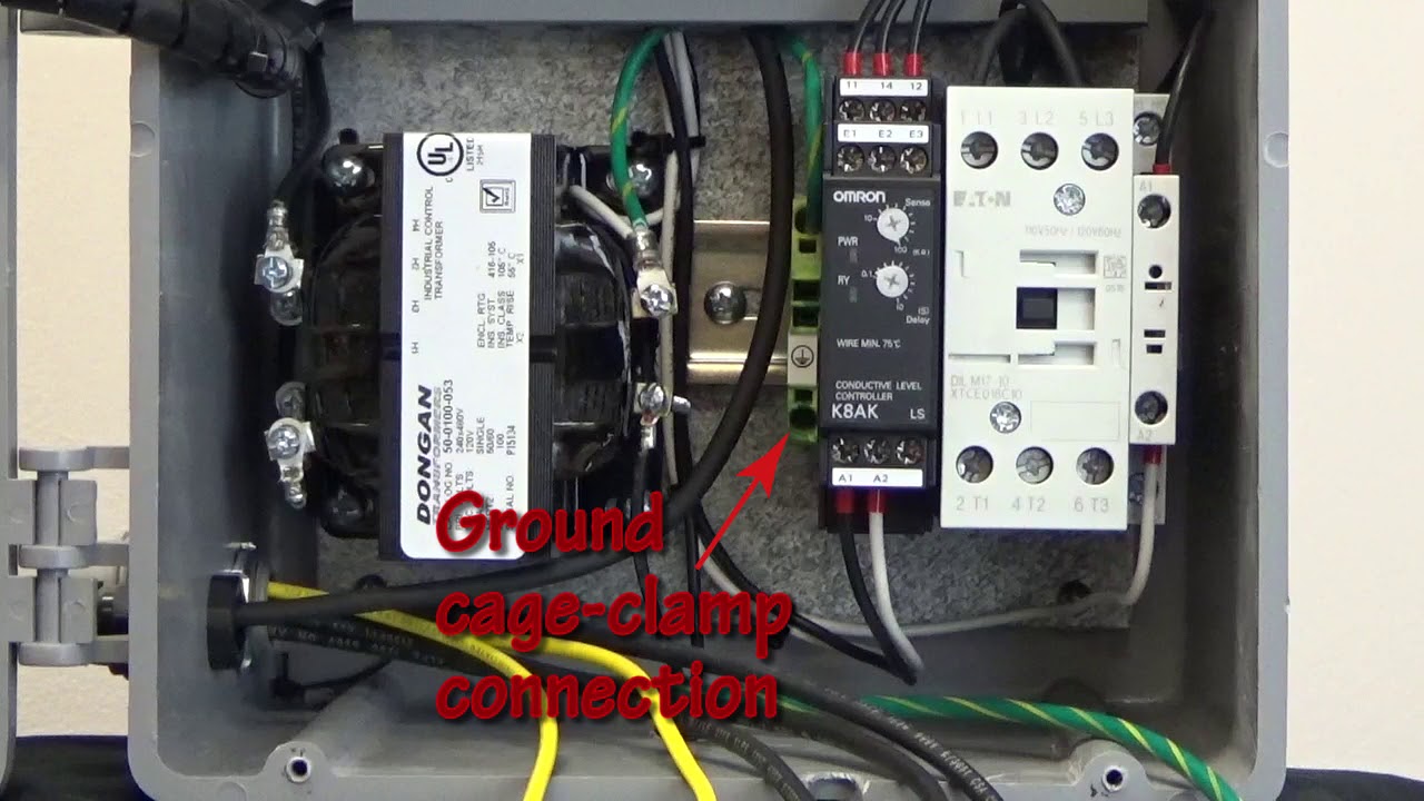
Duct heaters are designed for heating of intake fresh air transported through ... The electric heater wiring diagram is shown at the internal wall of the ...

UL & CSA LISTED ELECTRIC DUCT HEATERS STOCK- LINE SERIES ...
ELECTRIC HEATERS • O. & M. 6 ©March, 2007 Environmental Technologies FIELD WIRING NOTE: Prior to installing any wiring, check the unit name plate for main power voltage, control voltage and maximum overcurrent protection. Operating a heater at other than the specified voltage and phase can result in fire or electrical hazard.

In-line Duct Heater | rickardair
wiring diagram permanently fixed to the control panel of the heater. Heaters must be furnished with proper safety and warning labels to warn of electric shock hazard. Heaters must be furnished by the manufacturer with installation instructions. ELECTRICAL OPTIONS: kW Range .1 to 1000 Power Voltage: 120 to 600 VAC Phase: Single or Three

Anacon Power & Controls - APCSCR Series Power SCR Controller ...
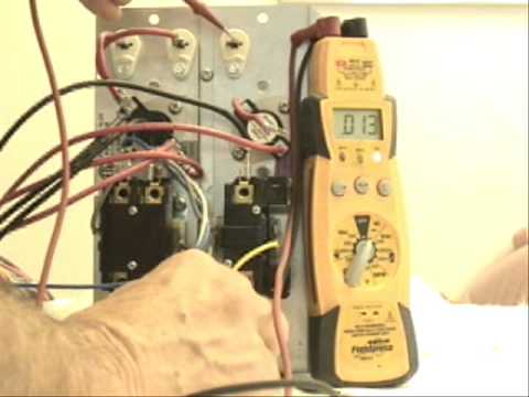
www.supercoolsliderule.com -- This video tutorial will illustrate with a wiring schematic and photos how an electric heater operates. Some troubleshooting wi...
General inspections, all models: Operating requirements ...
duct heater consists of attaching round duct to the inlet and outlet collars and bolting in place. Seal connection and duct joint. Model RCMP (Remote Control Panel) Install the control panel in a suitable location for the specified panel type. The wiring diagrams inside the heater door and the remote control panel door show point-to-point interconnecting
Open Coil Electric Duct Heaters Sales Flyer
Valid Air® High Performance Air Diffusers. Zebra Precision Air Valves. Electric Heating Products. Unitary Electric Heaters. Stock-line Duct Heaters. Quicksilver Duct Heaters. Custom Built Electric Duct Heaters. Resources. Manuals / Diagram / Labels / Drawings / Catalogs.

In-line Duct Heater | rickardair
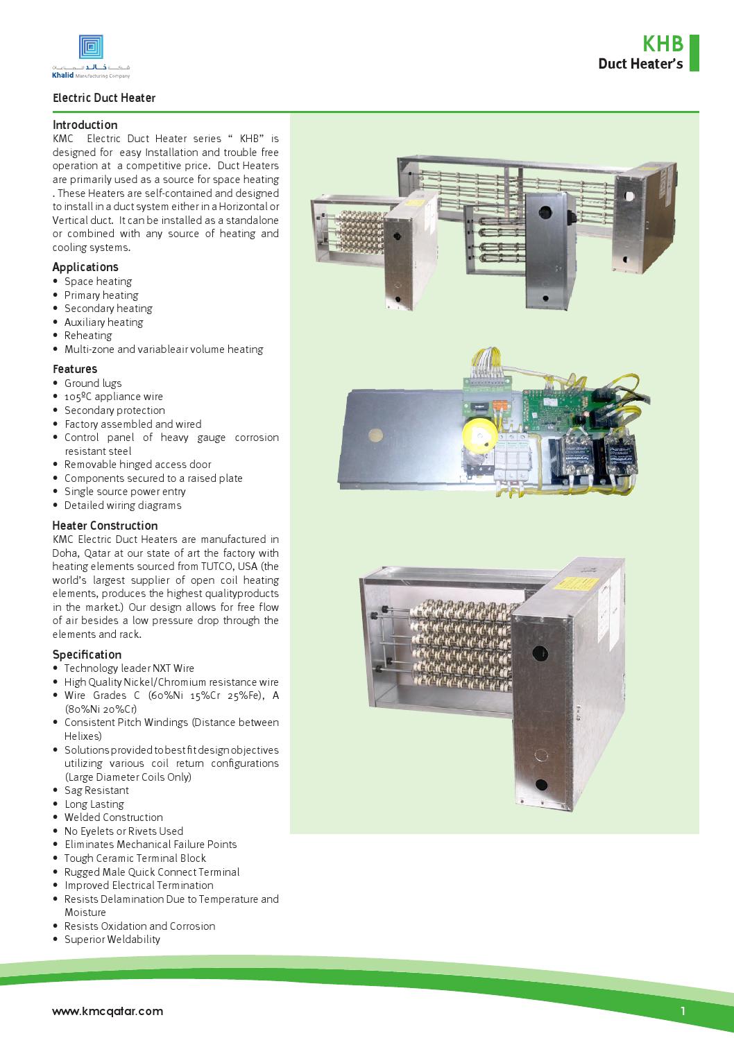
Each electric duct heater's unique design allows air to flow freely for the lowest possible pressure drop. Our heaters are factory-assembled and wired for the electrical specialties and controls of each project, and are available with round duct connection collars. The heaters are shipped loose, can be duct-installed onsite and are designed

Ventilation electric heaters VENTS NK…U (rectangular) |VENTS
the heating section of the heater. Slide the heater into the duct. Use the holes in the controls box as a template for locating the mounting holes in the duct. Remove the heater and drill mounting holes. Replace the heater and mount into the duct with sheet metal screws. Connect the high and low voltage wiring as shown on the attached wiring ...

ELECTRIC DUCT HEATERS - PDF Free Download
These duct heaters are not intended for installation in series in the air- stream; the heaters are designed for use only as a single unit within a duct ... Follow the wiring diagram on the inside of the terminal box. 15. ... National Electric Code for 75 °C copper wire with not more than 3 conductors in a raceway. The amperages shown are for ...
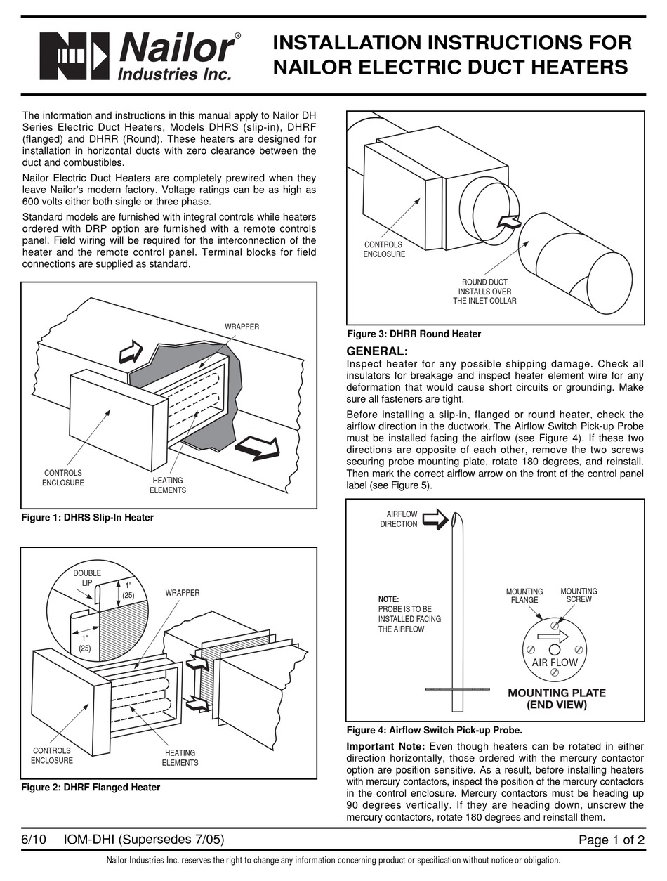
NAILOR ELECTRIC DUCT HEATER INSTALLATION INSTRUCTIONS Pdf ...
• DHRS •Slip-in Electric Duct Heater • DHRF Flanged Electric Duct Heater • DHRR Round Electric Duct Heater Duct Size • W x H (Specify) Airflow/Overhang • Horizontal/Left (standard) (default) • Horizontal/Right • Horizontal Bottom Mount (Centered) • Vertical/Panel Down • Vertical/Panel Up Line Voltage/Phase • 120V/1 ph.
MR Instal Instr 9-10-09 English
A duct heater must be installed according to the installations instructions, wiring diagram and labeling supplied with the heater. Listed below are some important items when installing an electric duct heater: 1. Never operate a duct heater without airflow. The heater must always be interlocked with the fan. This may be accomplished by either an
Custom Built Electric Duct Heaters – Warren HVAC
electric heating and controls

Hotpod electric duct heater installs in existing ductwork ...
HVAC Electric Heat strips
Heater Wiring

Grand Electric Duct Heater - ShanControls
Chromalox

Duct Heater Manufacturer, Duct Heater Manufacturers In India ...

Introduction INDEECO desi

How the duct heater works

Electric/ oil hybrid wiring system - DoItYourself.com ...

Finned Duct Heaters

Warren SL15T Electric Duct Heater
Custom Built Electric Duct Heaters – Warren HVAC
General inspections, all models: Operating requirements ...

Open Coil Electric Duct Heaters Sales Flyer
ELECTRIC DUCT
![Duct Heaters - [PDF Document]](https://reader020.staticloud.net/reader020/html5/20190804/55cf9931550346d0339c19c4/bg4.png)
Duct Heaters - [PDF Document]

Duct Heater description diagram English - Wattco
EK SERIES Electric Duct Heater
General inspections, all models: Operating requirements ...
3 phase immersion heater ke connection|YK Electrical
Electric Duct Heater by Abi Gfx - Issuu
Furnace Gas Heater Wiring Diagram Natural Gas PNG, Clipart ...


Comments
Post a Comment