42 linear actuator wiring diagram
Linear Actuator Wiring Diagram Generator. This handy tool is used to give you the right Linear Actuator wiring diagram depending on your project requirements. Step 1: Select how many actuators you will be using. Step 1b: If you selected 2 or more actuators for step one then you are presented with a few extra questions. Step 2. Here you will find list of wiring diagrams to control linear actuators with the help of switches and remotes. A lot of wiring schemes for your project.
Warner Linear Actuators…Customer Focused, Quality Driven Products designed and manufactured for reliable, long-lasting performance Quality Processes Thomson is proud to offer Warner Linear actuators. We are dedicated to designing and manufacturing “best-in-class” electromechanical actuators and controls.

Linear actuator wiring diagram
connection wiring (wire numbers 17, 17A, 18 or 18A per electrical wiring diagrams Figures 1 and 2 on page 4 and 5). This could cause serious damage to the actuator or the driven equipment. WARNING 11. Do not hammer or gouge the outside surface of the extension rod. This may damage the plating integrity or cause surface irregularities which can Linear Actuator Wiring. Here are a number of highest rated Linear Actuator Wiring pictures on internet. We identified it from trustworthy source. Its submitted by organization in the best field. We assume this nice of Linear Actuator Wiring graphic could possibly be the most trending topic behind we portion it in google help or facebook. Sample Wiring Diagram: This diagram shows a simple wiring diagram that will allow you to manually switch power in either direction of the actuator travel. MPC Linear Actuators for Wiring, Switch and Relay Kit: schematron.org: ECO-WORTHY 12 Inch Linear Actuator 12'' Stroke DC 12V Heavy Duty Pounds . perfect instructions, worked perfectly for my snowblower chute actuator, took.Apr 24, · Showing how to wire linear actuator.
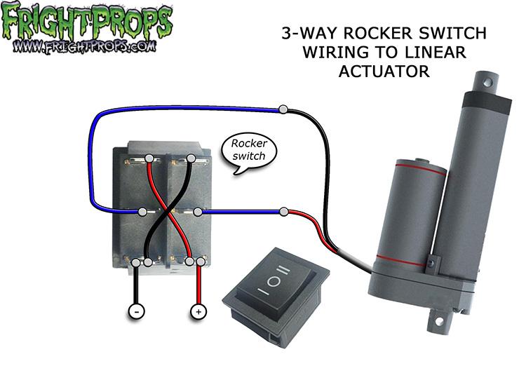
Linear actuator wiring diagram. LRA Linear Residential Actuator Installation Guide - 2 - 228158 Revision X17 8-11-2011 Linear Actuator Operator Overview The Model LRA Residential Linear Actuator is designed to open and close a light-duty residential swing gate. The operator can be used in left-hand or right-hand swing gate Nov 26, 2021 · Wiring diagram of a rocker switch to an actuator The linear actuator wiring diagram above can be achieved by following a few steps: The upper-left and lower-right terminals must be connected to the ground of the power supply. The upper-right and lower-left terminals must be connected to the +12V terminal of the power supply. ML6425, ML7425 SPRING RETURN ELECTRIC LINEAR VALVE ACTUATORS 63-2516—08 4 Fig. 2. Attaching Actuator to Valve Collar. Fig. 3. Securing Actuator to Valve. Fig. 4. Removing Actuator Cover. Fig. 5. Removing Spring Retaining Clip and Releasing Manual Spring Handle. WIRING CAUTION Electrical Shock or Equipment Damage Hazard. Linear Actuator Diagram. Published by. Judith. Thursday, January 20, 2022. figure 5 5 electromechanical linear actuator wiring diagram. Linear Actuator Diagram. Here are a number of highest rated Linear Actuator Diagram pictures on internet. We identified it from honorable source. Its submitted by direction in the best field.
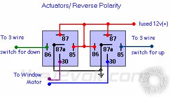
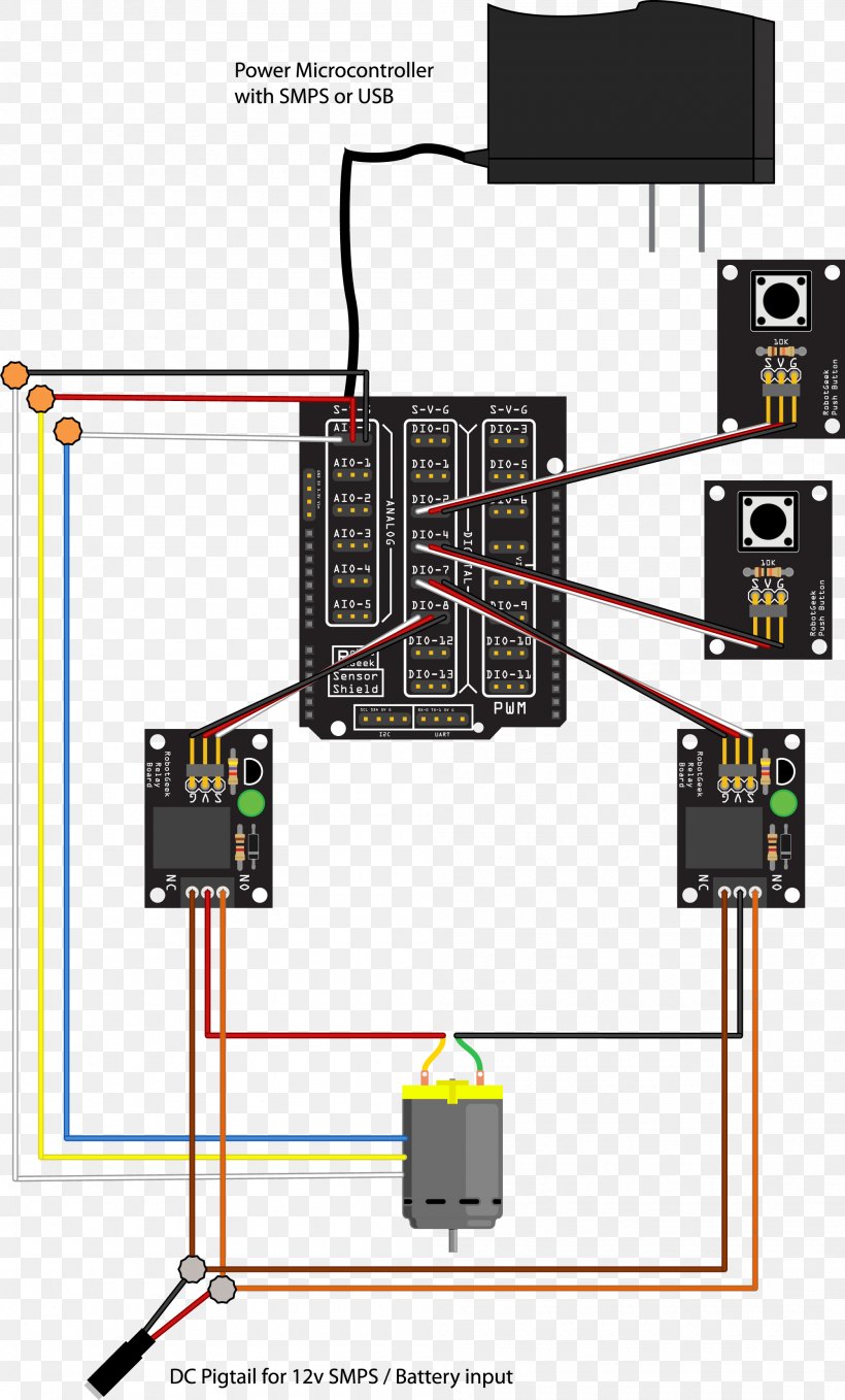
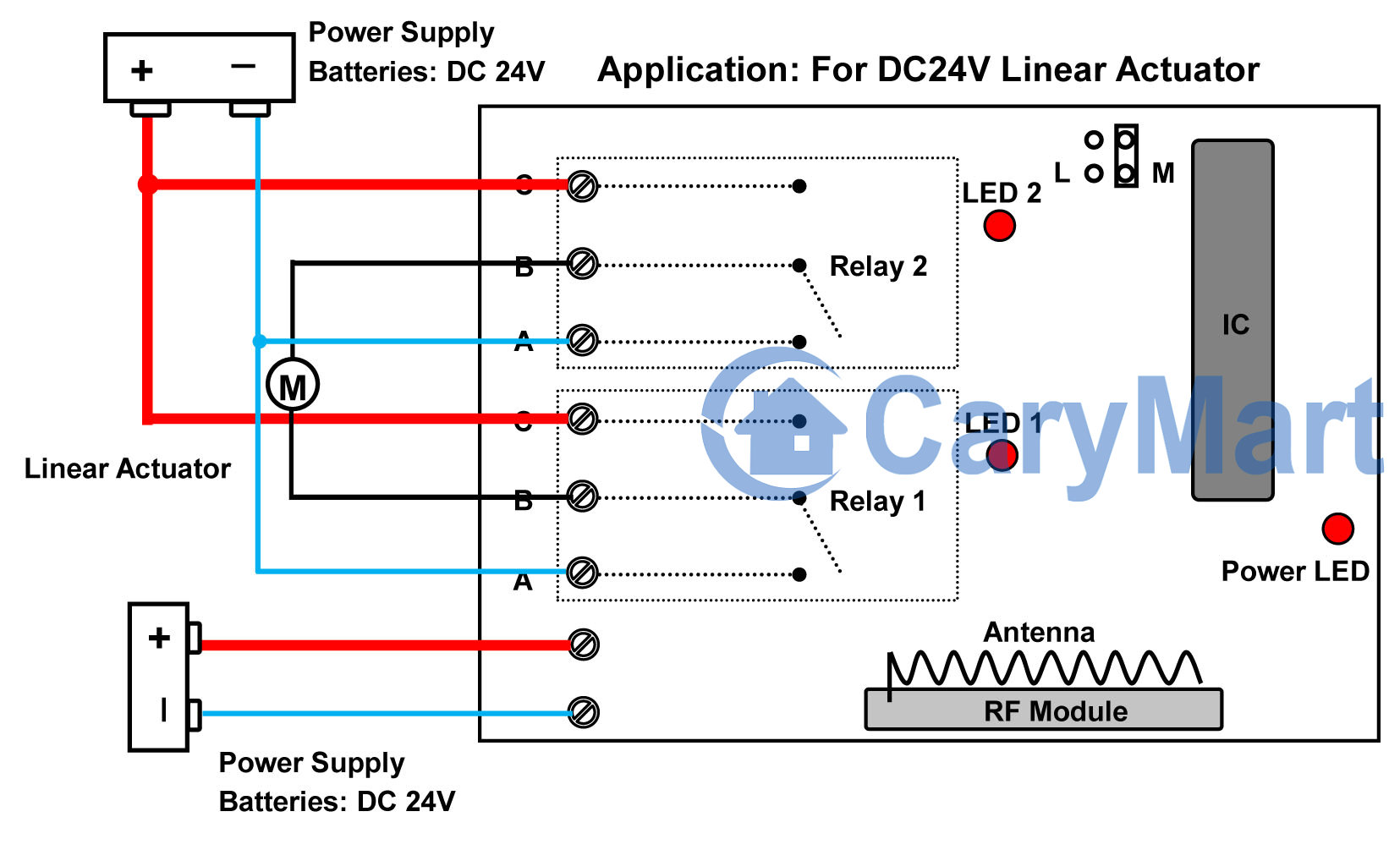
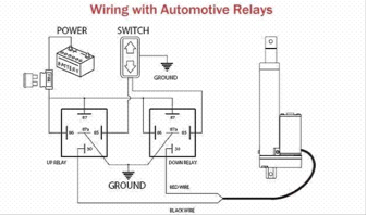
3,563 Posts. #2 · Mar 12, 2017. Howdy gismo, I found two you tube videos and a wiring diagram that might be useful: 1. How to connect a linear actuator to a rocker switch: Full instruction. you tube. 2. How to wire a linear actuator to a 3-way toggle switch. you tube. Do an internet search for each of the above. - Wire the relay according to the diagram above (12V Relay Wiring) - Connect T3 and T7 to the positive terminal (12V) of your power supply - Connect T4 and T8 to pin 8 of the relay - Connect the positive side of the actuator (red wire) to pin 5 of the relay - Connect the negative side of the actuator (black wire) to pin 6 of the relay Ask Question Here is an easy 5 wire setup for anyone to use in any vehicle without the use of any relays. 5 wire actuator diagram. Wiring diagram in our example we use the rocker switch. Connect the negative terminal of the power supply to the t3. Follow the instructions described in the linear actuator wire diagram. Actuator spring door actuator wiring 5 ... Learn how to control linear actuator using Arduino, how to control linear actuator speed and direction, how to connect linear actuator to Arduino, how to program Arduino step-by-step. The detailed instruction, code, wiring diagram, video tutorial, line-by-line code explanation are provided to help you quickly get started with Arduino.
By reversing the actuator's two leads, it's possible to reverse this effect. This would cause the actuator to remain extended full-time, and retract at the push of a button. How To Connect The Actuonix Relay Kit I've included a wiring diagram below that shows you exactly how to connect your actuator to the Actuonix relay kit. Jul 24, 2021 · Wiring Diagram Linear Actuator Actuator Linear . Over 65 years of field service all over the world in oil and gas water and wastewater marine power generation refineries marine and chemical plants emerson s bettis and eim electric actuators have become the industry standard in valve control. ACTUATOR (Terminal Block J1): The actuator and feedback potentiometer are connected to terminal block J1 as shown in the wiring diagram. Terminal 1 should be connected to the motor winding that moves the actuator toward the open position, and conversely, terminal 3 is connected to the winding that moves the actuator toward the closed position. May 30, 2012 · RC-01 Rocker Switch: https://www.progressiveautomations.com/products/rc-03AC-03 12 Volt Battery: https://www.progressiveautomations.com/products/ac-03Learn h...
How to wire up this linear actuator - Quora
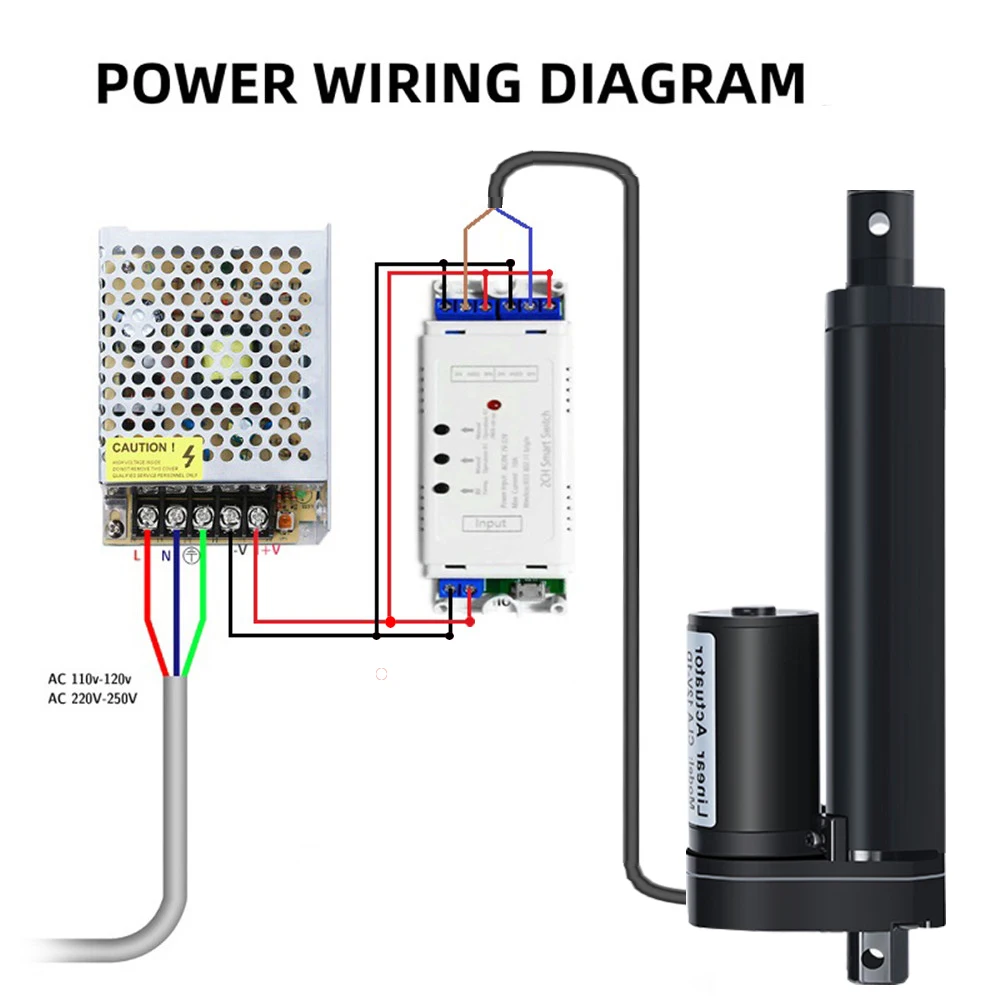
Wiring Thomson linear actuators should be connected in accordance with the diagram show below. Make sure power is off before attempting to wire actuator. WIRE GAUGE SELECTION DC Actuators Long lead wires between the power source and the actuator will result in a voltage drop for DC units.

12 Volt Electric Linear Actuator Wiring : 3 Steps - Instructables
May 04, 2018 · linear actuator wiring diagram – What is a Wiring Diagram? A wiring diagram is an easy visual representation in the physical connections and physical layout of the electrical system or circuit. It shows the way the electrical wires are interconnected and can also show where fixtures and components may be attached to the system.

Arduino - Actuator | Arduino Tutorial
Generate a custom wiring diagram for your linear actuator projects. This handy tool is used to give you the right Linear Actuator wiring diagram depending on your project requirements. Step 1: Select how many actuators you will be using. Step 1b: if you selected 2 or more actuators for step one then you are presented

Potentiometer Feedback Linear Actuator | FIRGELLI
Below is a diagram showing you exactly how to wire up your actuator to a DPDT rocker switch. If you choose to use our lighted push-button switch rather than the rocker, the wiring is almost exactly the same. The terminals have different designations and the switch is round rather than rectangular.

China Waterproof Linear Motor Manufacturers, Suppliers ...
This item: MPC 0462 Linear Actuators for Wiring, Switch and Relay Kit. $34.95. In Stock. Ships from and sold by Amazon.com. FREE Shipping. U-Shape BRK-02 mounting Bracket for Linear Actuator | Made with Iron Steel | Can be Used with Progressive Automations Linear Actuator Model PA-03, PA-04. $12.70.
linear actuator wiring | Tractor Forum
Linear Actuator Wiring - I have a linear actuator (model# lact6p from SPAL)that im trying to make it extend when ignition is on,and down when ignition is turned off.I see that they make a controller for it but i really dont want any switches added.This partiticular model of actuator has five wires n

Actuator Control with External Limit Switch - Progressive ...
This is the suggested schematic. You would need to solder a wire to the junction of the relay coil and it's driver transistor for each relay. The two diodes to the relay coils could be 1N4148s The diodes in parallel with the limit switches need to carry tha actuator current so I would suggest 3 amp rating diodes.

Restrict Stroke Length of Linear Actuators with External Limit Switch Kit
Jun 03, 2020 · warner linear actuator wiring diagram – What’s Wiring Diagram? A wiring diagram is a form of schematic which uses abstract pictorial symbols to demonstrate all of the interconnections of components in a very system.
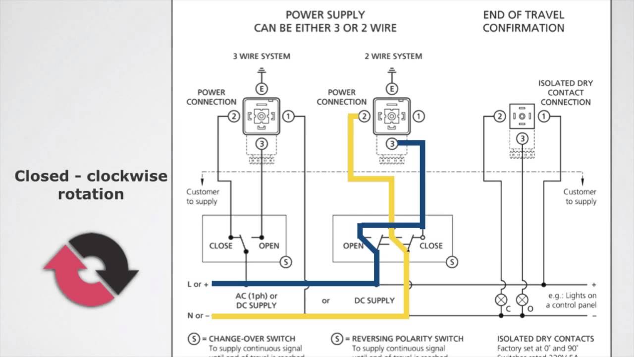
S4 Multi-Voltage Reversible Electric Actuator Wiring Instructions
Firgelli Automation is proud to present our Linear Actuator Wiring Diagram Generator. This generator has been developed to show you how to connect your linear actuator (s) to our control system products to meet the specific needs of your project. Along with our Linear Actuator Calculator, our online tools will make designing your next project a breeze.
wiring linear actuators to alarm
2-3. Wiring Connections-Single Phase All wiring connections must be made to the pigtail electrical cable. Refer to the following table for wire ... as shown in the diagram, bridging W2,U2, and V2. 3 Phase Motor and Brake Connection 2-5. Limit Adjustments ... LINEAR ACTUATORS ...

15mm Can-Stack Stepper Motor Linear Actuator | Haydon Kerk ...
Step 1: Wiring With a Rocker Switch. The simplest control system for a 12VDC linear actuator for a user to implement will have to be a DPDT (double pole double throw) rocker switch. It can output DC current in both directions from the power supply, therefore it can control the linear actuator to extend and retract.

Linear actuator control box - Motors, Mechanics, Power and ...
This handy tool is used to give you the right Linear Actuator wiring diagram depending on your project requirements. Select how many actuators you will be using. (If you selected 2 or more actuators, you will be presented with a few extra questions) Pick which control options you wish to use. Add on any additional features, such as a speed controller or external micro limit switch, or even speed control.

Components Of Electric Linear Actuator – Progressive Automations
Sample Wiring Diagram: This diagram shows a simple wiring diagram that will allow you to manually switch power in either direction of the actuator travel. MPC Linear Actuators for Wiring, Switch and Relay Kit: schematron.org: ECO-WORTHY 12 Inch Linear Actuator 12'' Stroke DC 12V Heavy Duty Pounds . perfect instructions, worked perfectly for my snowblower chute actuator, took.Apr 24, · Showing how to wire linear actuator.
Actuator LA36/LA37
Linear Actuator Wiring. Here are a number of highest rated Linear Actuator Wiring pictures on internet. We identified it from trustworthy source. Its submitted by organization in the best field. We assume this nice of Linear Actuator Wiring graphic could possibly be the most trending topic behind we portion it in google help or facebook.

Using a Shelly 2.5 to control a linear 12v actuator... wiring ...
connection wiring (wire numbers 17, 17A, 18 or 18A per electrical wiring diagrams Figures 1 and 2 on page 4 and 5). This could cause serious damage to the actuator or the driven equipment. WARNING 11. Do not hammer or gouge the outside surface of the extension rod. This may damage the plating integrity or cause surface irregularities which can
Linear Actuator Arduino Wiring Diagram Relay, PNG ...
12V DC Motor Linear Actuator Wireless Remote Control DPDT ...
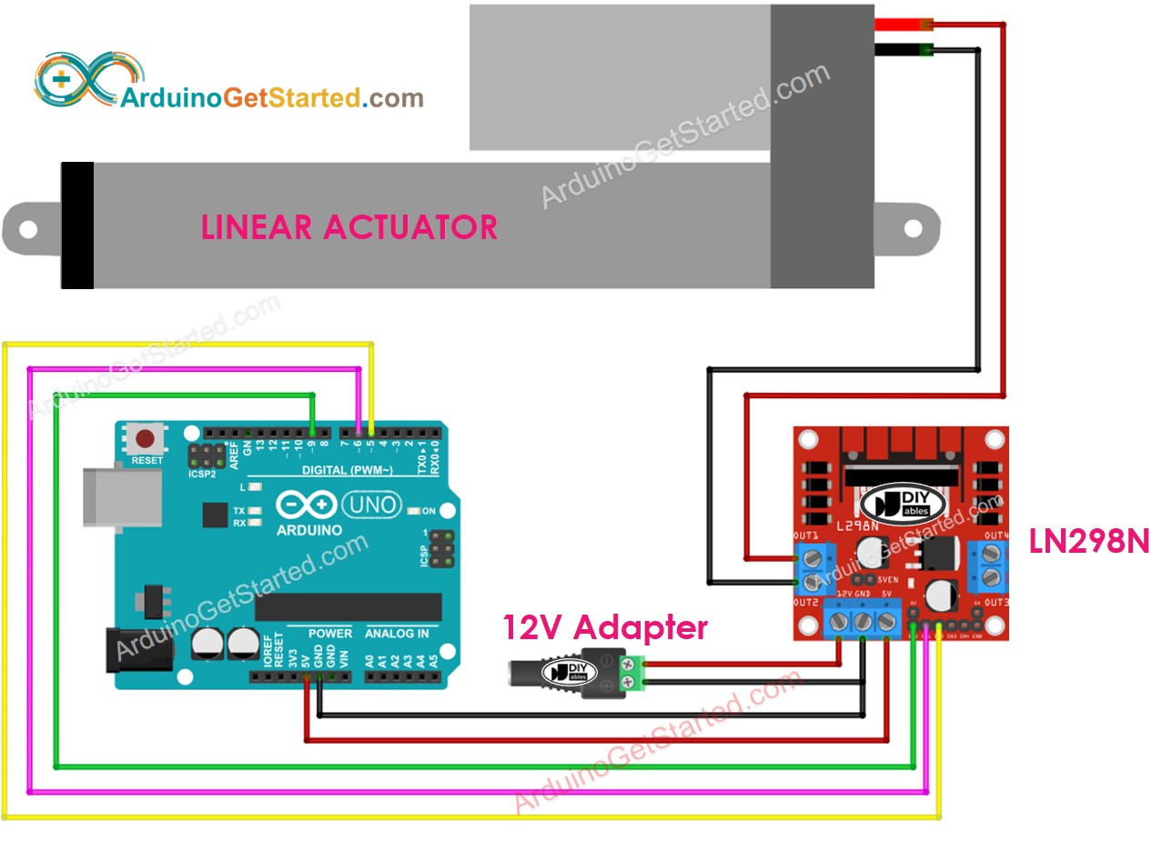
Arduino - Actuator | Arduino Tutorial

Ektroniksigaram: Ac Linear Actuator Wiring Diagram

Dual Linear Actuator Controller - Northern Tool Pages 1 - 6 ...

External Limit-Switch Kit for Actuators | Linear actuator ...

Connecting a Linear Actuator to a Rocker Switch - Instructables
Linear Actuator

GLA1500-N High Force Low-Noise 12V DC Linear Actuator ...

Valve actuator Wiring diagram Butterfly valve Control valves ...
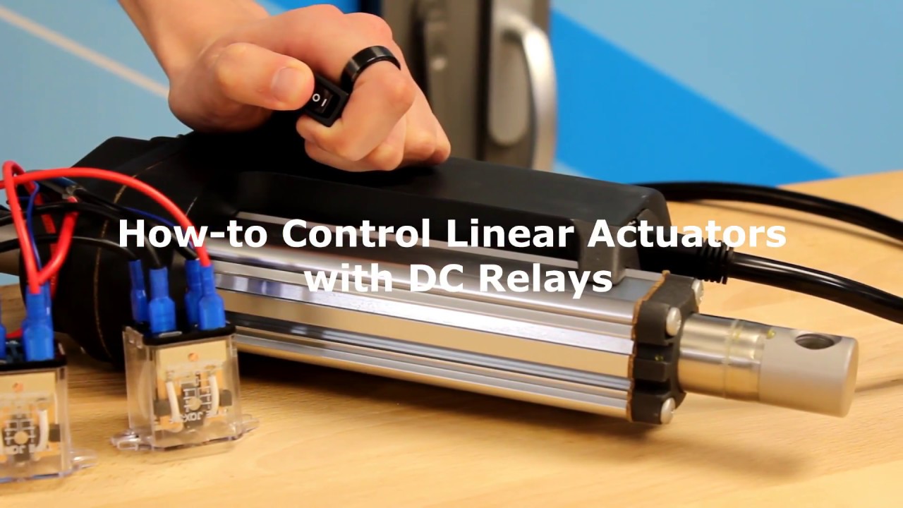
How To Control Linear Actuators with 12 VDC Relays

Actuator, Actuators, Linear Actuators, Electric Linear ...
FrightProps | FrightProps Support & Training Center
linear actuator – Remote Control Everything
Linear Actuator 12V Wifi DIY Smart Wireless Remote Switch linear actuator Controller Module Work with Alexa Google Home eWeLink

External Limit-Switch Kit for Actuators | Linear actuator ...

Wiring a Servocity Linear Actuator with Feedback to an ...

Linear Actuator Manufacturing Wiring Diagram Bearing PNG ...
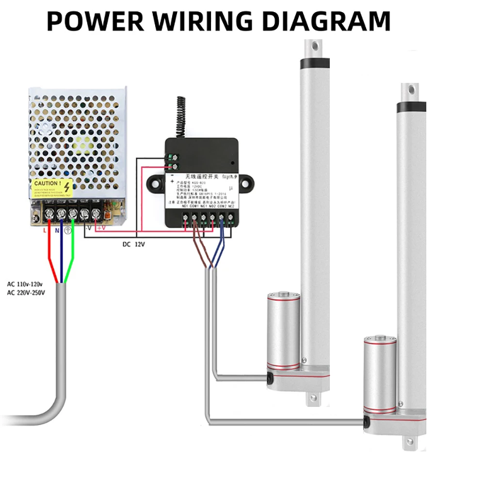
1*RF Remote Controller + 2*Linear Actuator 12V +Power Supply 800mm 900mm 1000mm stroke Electric DC Synchronous Motor

12 Volt Electric Linear Actuator Wiring Diagrams ...

Amazon.com: WindyNation Linear Actuator or DC Motor Power ...

DIY Linear Actuator Controller

12 Volt Electric Linear Actuator Wiring : 3 Steps - Instructables
How to Power a Micro Linear Actuator - The Engineering Projects
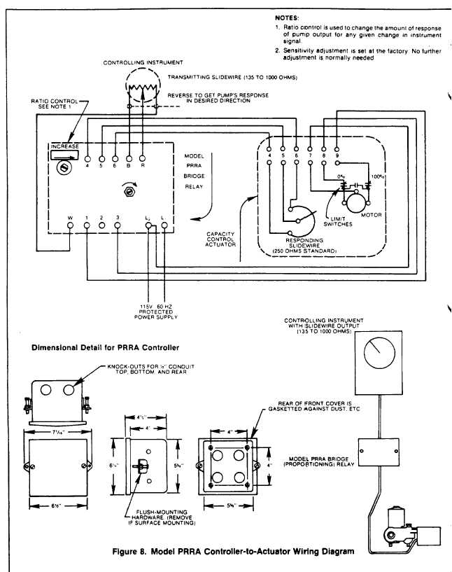
Figure 8. Model PRRA Controller-to-Actuator Wiring Diagram
Linear Actuator
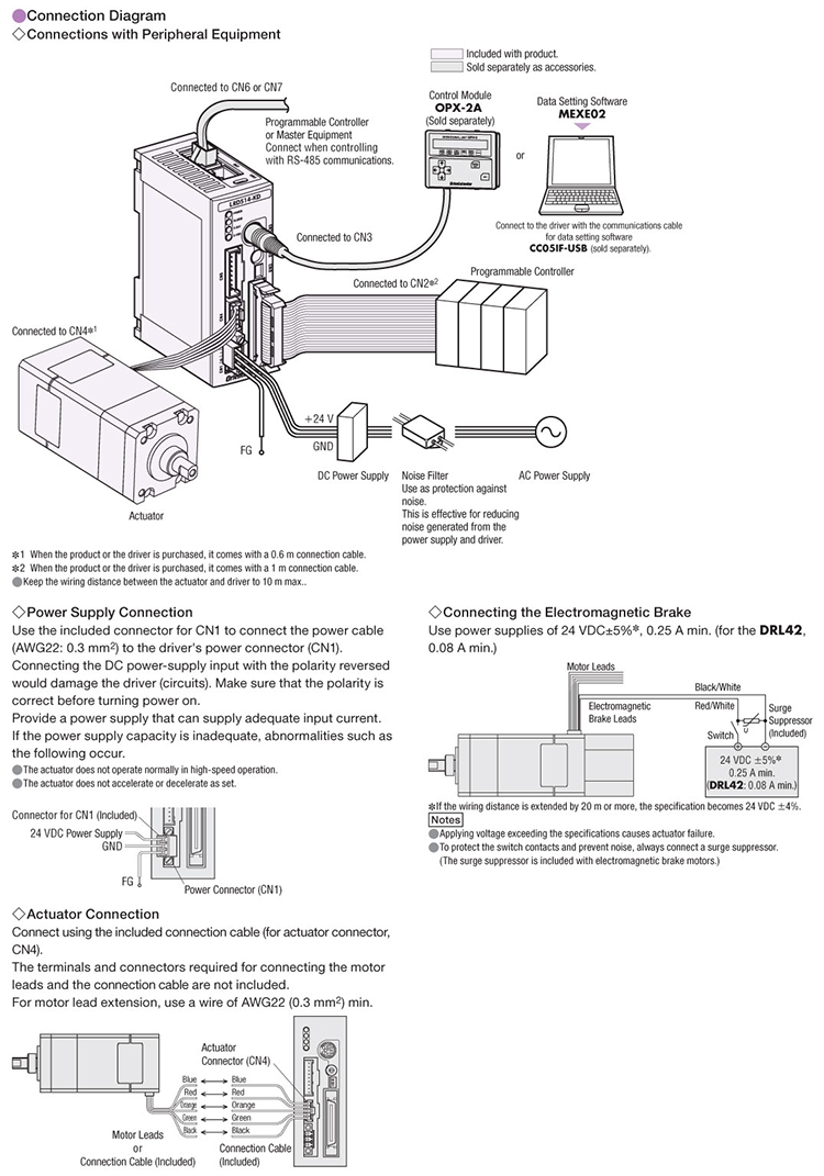
DRL60G-05B4P-KD Compact Linear Actuator and Driver


Comments
Post a Comment