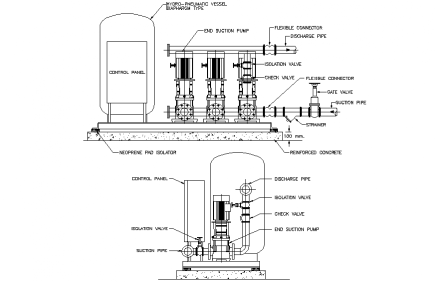
43 booster pump installation diagram
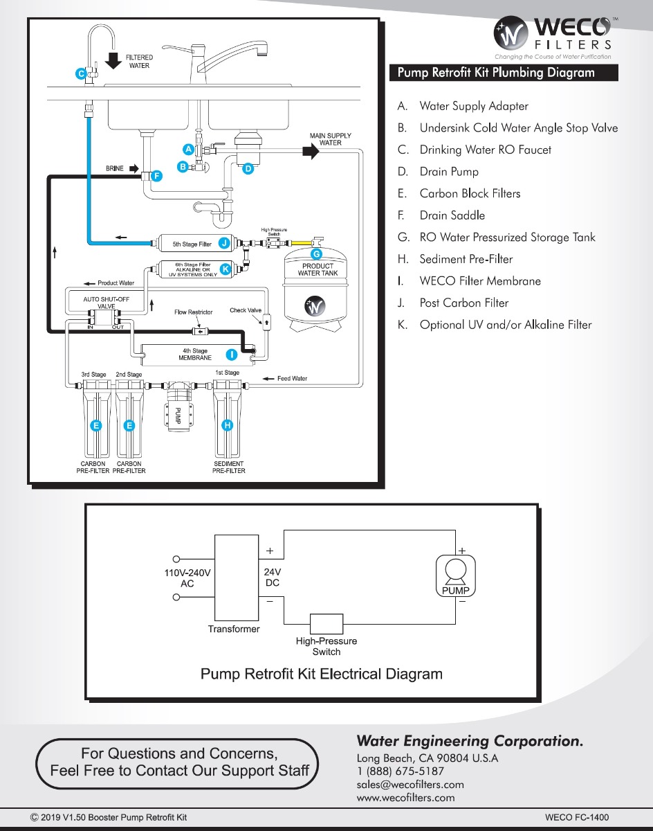
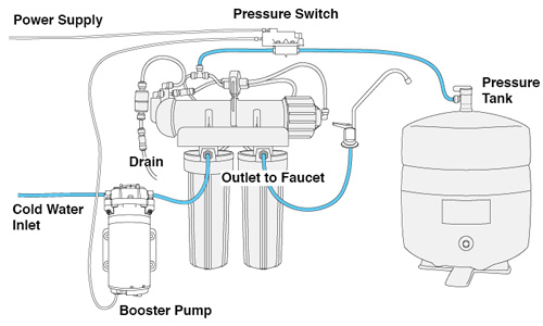
13) Congratulations, you have completed installation of the vacuum pump! Before you start the vehicle, review the simplified wiring diagram pictures below to make sure all of your connections are correct: To ground (-) Relay terminal 3 To vacuum switch Relay terminal 1 To (-) pump (black) Relay terminal 5 (+) 12 volt Relay terminal 2 To ... Open the ledge faucet and keep it open to relieve pressure. Position the pump so that the inlet tube — the 1/4 tube that supplies water to the RO unit — can be routed through it. Observe the directional arrows on the quick-connect fitting ports at the front of the pump, cut the inlet tube squarely and insert the ends into the appropriate ports.
3. Cut the 3/8" factory brake booster hose again and insert the supplied Y-connector (Fig. #2) between the check valve and the brake booster. 4. Connect 1/8" hose from vacuum pump. (Fig. #3) 5. Next connect the red wire from pump to 12 volt source. For more information about wiring look at other side of this paper. 6.
Booster pump installation diagram
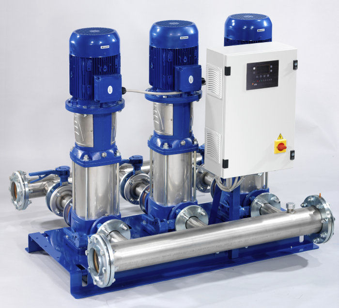
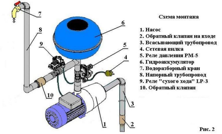
straining element. They are used in pipelines to protect pumps from solid dust and waste materials entering the pump and the pressure tank. It is strongly recommended to install Strainers to avoid clogging, so it doesn't disturb the functioning of Pressure Boosters. Before starting; pre-filling of the pump with water is mandatory, INSTALLATION WIRING DIAGRAM - 115VAC - TWO-WIRE PUMPS For 115 Vac motors exceeding 16 full load amps, use magnetic starter to avoid damage toMascontrol®. See separate magnetic starter wiring diagram.! WARNING 22 Remove pressure switch from surface pump and wire Mascontrol® directly to pump. IMPORTANT AUTOMATIC PRESSURE BOOSTER PUMP • The automatic pressure switch is governed by the water pressure in the pipe line • The 5-way connector holds the pressure switch and pressure guage and the hydrospere screws ontop (see diagram below) • The water inlet (25mm) is connected to the front of the pump, and the outlet to the
Booster pump installation diagram. heater discharge (see the Typical Installation diagram). DO NOT TAP THE BOOSTER PUMP INLET INTO THE THREE-FOOT SECTION OF HEAT SINK PIPE THAT COMES DIRECTLY OUT OF THE HEATER. Installation with a Solar System The booster pump must be installed so it is always in the water flow (see the diagram below). Some solar heating systems are designed to use Note: The attached specification sheet shows a typical R.O. system diagram for reference. If you want to retrofit another type of R.O. unit (a manifold type) or if your system has another configuration of hydraulic shut-off valve, or if you are using an electric booster pump, consult factory for instruction. 1-800-955-8561. Mon - Fri • 9:00 AM - 5:30 PM ET. sales@h2odistributors.com. The Polaris booster pump supplies high pressure water to The booster pump motor is factory wired for cleaner, refer to the Typical Installation diagram. I have a new polaris pb booster pump that I bought to replace an PB Q, both V old pump had wire diagram for connections.
The installation of a booster pump on a city water system, or even a rural water system, that uses gravity-fed water, is quite easy. All you need to do is take the main water line as it enters the house and feed it into a booster pump. The output of the pump goes to a water-pressure tank, and the output of the tank then goes to the house water ... Booster Pump Installation Instructions 1. Install pressure switch in tank line. (See diagram on back for where to place the pressure switch). 2. Pump must be located within 2 feet of pressure switch and within 6 feet of power outlet. A. Pump can be mounted to the wall horizontally in either direction or vertically only one way ~ with pump head and After guidelines have been met, connect the booster pump wiring to the motor contractor located in the control panel (ref control wiring diagram in the control panel). Connect the three-phase power source to the Main ON/OFF switch located inside the control panel. Connect the flow switch wiring to the control Good day, ladies and gentlemen. For your consideration, I'd like to present what I believe to be the safest and mod-friendly wire diagram for a custom ESC installation, in this case 24V. I believe I have wired in two separate fail safes, both of which can be triggered by driver and one of which can be triggered remotely if desired. My wiring diagram can be used for 12V or 24V installations but for 12V you need to basically correctly choose your relays, ESC, and put the 12V LEDs in parallel so t...
Diagram of a 4 stage Reverse Osmosis system with Booster Pump and Permeate Pump. Click on the PDF emblem and you will be transferred to the diagram. There is additional information on this web site for installation of the RO system. Click on Instruction Manuals and you can mouse down and locate the RO Installation Instructions. Multistage Booster Pump System KQ Series ISO 9001 Certified KQ200/400 KQ800 . 1 ... bolt the booster pump securely. The installation place must be dry with good ventilation and adequate space for future maintenance and service. A proper ... diagram shown below or inside the cover. We are in the process of buying a row house in Northern Liberties, and during the inspection today, we found that the water pressure on the third story of the house is rather low. The basement, first, and second floors' water pressures are all fine, so this seems like a straightforward height limitation, not a breakdown (the house is also 6 years old, so pipe age is unlikely to be a factor). Is getting a booster pump the right answer here? Would it be on the main line, or is there way to add a ... 12 Volt Vacuum Pump Installation Instructions Instructions: 1. Mount the vacuum pump. 2. Connect the vacuum fittings, hoses, switch, and filter as shown in the diagram. 3. Connect the black wire from the vacuum pump to a ground. 4. Connect the red wire from the vacuum pump to one of the terminals on the vacuum switch. 5.
Installing FC-1400 RO Booster Pump Retrofit Kit - Video
Booster Pump The Reverse Osmosis in line booster pump will increase the incoming water pressure after pre-turbidity and carbon filtration stages to 100psi for maximum efficiency and production quality through the Reverse Osmosis TFC membrane TDS removal process. Power standard outlet plug 110V / 60Hz is required. Faucet

Installation scheme of a centrifugal pump station (Booster No ...
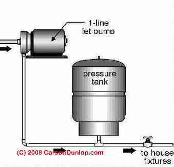
Diagrams --Typical Pump Installations. The information provided here is for educational purposes only. Technically qualified personnel should install pumps and motors. We recommend that a licensed contractor install all new systems and replace existing pumps and motors. Failure to install in compliance with local and national codes and ...
Tsunami Pump Water Pump Home Water Pump Automatic Home CMH2-30K Water Booster Pump Automatic Water Pam Air Rumah
Looking to have a ductless mini split installed to reduce heating costs (baseboard and gas fireplace now). Wondering if anyone has had a good experience with any local contractors and what I should expect to pay for a unit with 4-5 heads. Thank you!

Aquatec booster pump installation question | REEF2REEF ...
the LA01N booster pump it manufactures, including all parts and components thereof, to be free of defects in material and workmanship. The warranty commences on the date of installation of the pump and shall remain in effect for a period of twelve months, but in no

Zamboanga City Water District - SCHEMATIC FOR PROPER ...
Submersible Pump Control Box Wiring Diagram For 3 Wire Single Phase Submersible Pump Submersible Electrical Circuit Diagram. Automatic Water Level Controller Wiring Diagram For 3 Phase Motor Submersible Pump Water Pump Motor Submersible Pump Electrical Installation. Booster Pump Explain New 2017 Youtube Well Pump Refrigeration And Air ...
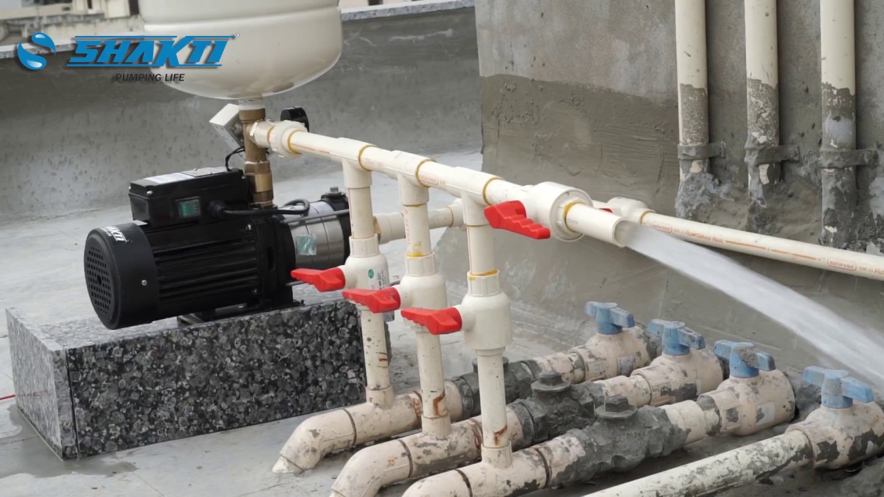
How to Install SH Pressure Booster Pump? Learn From the Video
† Example: If PB0508A031 pump is connected to supply line of sufficient capacity, carrying water at 40 PSI, and the output of the pump is held to 7.3 GPM by a gate valve, the pump will add 40 PSI to line pressure for a total output pressure of 80 PSI. * Operation of pump in this range may result in reduced pump life and/or motor damage.

Warthog Booster Pump Maintenance
Hey androidapps community, I am a part time indie developer. I created a pretty niche app to help my work, and I am keen for new users and feedback. I am not really focused on the money, and I am willing to give out free licenses to the app for those who spread the word and give feedback. To be frank, I put my heart into this project, worked really really hard on it, but by now I am deeply fatigued and tired of it. But I still... I want to serve some justice to it by promoting, so I hope that s...
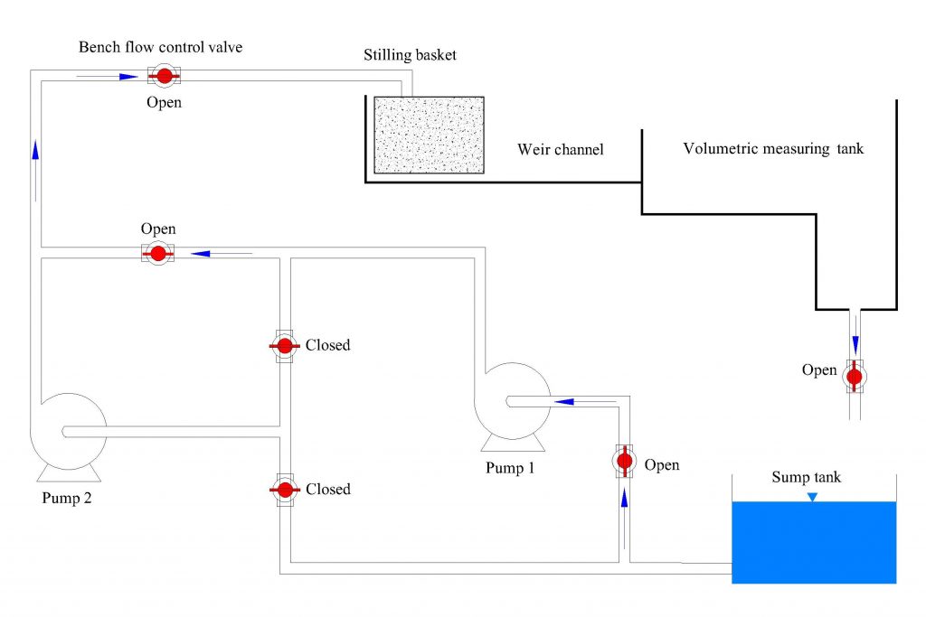
Experiment #10: Pumps – Applied Fluid Mechanics Lab Manual
• Pump is exceptionally quiet, and uses up to 40% less electricity than competitive booster pumps. • Pump design allows for easy installation and service. • Suitable for use with all pressure cleaners requiring a booster pump. • Tall mounting base allows for increased motor ventilation as well as protection from flooding.
Manual for Installation, Operation and Maintenance of
What did it cost you to remove an HVAC system and replace with a heat pump? Looking online is a race to the bottom on price, it seems. I'm not freakin' and I'm not calling beacon. I have a 2400-ish sqft house, and we like it on the chilly side up in here. We have a heat pump in a cabin we go to, so I know the trade-offs. I'm not really interested in hearing how long the energy savings will take to offset the cost. I'm strictly looking to stop burning fossil fuels where I can. Thanks to those w...

Shower booster pumps
Thanks to reader Ahmed Hamza for discussing the use of water pressure booster pumps and the installation of water pumps in series to improve water pressure on upper building floors. Mr. Hamza is in Cairo, Egypt where although he is not a plumbing professional, he works work with Calpeda Pumps , an Italian company that produces a wide range of ...

water tank installation | Water storage tanks, Water storage ...
A water booster pump is essential to boosting up water pressure and therefore increasing water flow to certain areas of the home. This is very helpful when you have a swimming pool, a fountain or small pond. Installing one at a home requires wiring it to the electrical supply.
5 Stage Point of Use RO System with Feed Booster Pump
The starting current of the booster pump motor may exceed 15 amps. It is recommended that a 20 amp service breaker be used for the pump. The booster pump motor is factory wired for 240 volts, but can be wired for either 120 or 240 volts. To rewire to 120 volt, follow the instructions on the name plate

schematic diagram of the new system with one booster pump for ...
Booster Pump Owner S Manual Model 6060. Booster Pump Package Operating Installation Instructions. Schematic diagram of the new system with one booster pump for each two scientific zamboanga city water district proper installation pumps a laws on use philippine clean act 2004 sanitation code philippines typical 𝐒𝐑𝐊 ...
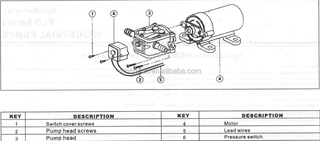
Starflo Flo-2202a 4.0lpm 80psi 12 Volt Mini Manual Electric ...
Internal Wiring Diagram Inline 400 Inline 400 Model No. 92061501 / 92061503 92061502 / 92061504 ... The Inline 400 is a simple to use "plug-and-play" water pressure booster system. At the heart of this fully integrated booster system is a trusted ... Decide on a location for the pump installation that is suitable based on the enclosure ...

Installation scheme of a centrifugal pump station (Booster No ...
How to install a Pressure Booster PumpKnow how to pump up the water pressure in your home with the help of a pressure booster pump. Pumpkart. Com is not only...
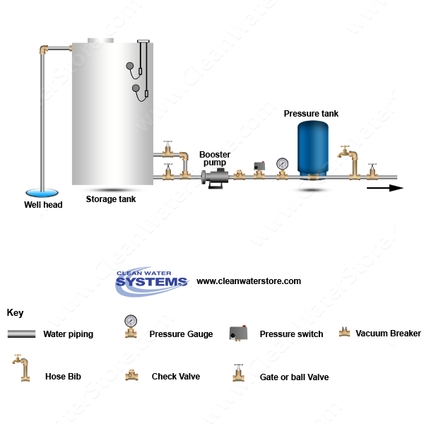
Well Water Diagram |Well > Storage Tank > Booster Pump ...
Due to space concerns (old Halifax homes), I can't install a Heat pump directly to an exterior wall. I was wondering if anyone here had experience with (or knows a contractor that does) installing a heat pump with the condenser mounted on a flat roof? The current contractor I've been working does not have experience with this - although they are very helpful and interested in pursuing with the help of a roofer. If possible I would prefer to work with someone with experience due to the possibi...
Booster Pump - Installation Instructions – Pure Water ...
Check my new video https://youtu.be/EqNenMs_Wrk booster pump repair,booster pump and pressure tank,booster pump installation,booster pump for washing machin...
Water pressure booster pump and tank guide - water pressure ...
Does anyone have a wiring diagram for the fuel pump on a 2017 6.7? After a lot of googlefication all I can find is for 7.3, 6.0, and 6.2. I’m installing a kill switch run to an upfitter switch in the cab for theft prevention.

The Booster Pump | ecexproblemsolved
AUTOMATIC PRESSURE BOOSTER PUMP • The automatic pressure switch is governed by the water pressure in the pipe line • The 5-way connector holds the pressure switch and pressure guage and the hydrospere screws ontop (see diagram below) • The water inlet (25mm) is connected to the front of the pump, and the outlet to the

Grundfos CM5-4PT Water Booster Pump Supply & Install ...
INSTALLATION WIRING DIAGRAM - 115VAC - TWO-WIRE PUMPS For 115 Vac motors exceeding 16 full load amps, use magnetic starter to avoid damage toMascontrol®. See separate magnetic starter wiring diagram.! WARNING 22 Remove pressure switch from surface pump and wire Mascontrol® directly to pump. IMPORTANT

Pressure pump installation user guide.
straining element. They are used in pipelines to protect pumps from solid dust and waste materials entering the pump and the pressure tank. It is strongly recommended to install Strainers to avoid clogging, so it doesn't disturb the functioning of Pressure Boosters. Before starting; pre-filling of the pump with water is mandatory,
AUTO RESTART PUMP CONTROL

WECO Reverse Osmosis (RO) Pressure Booster Pump Kit: Amazon ...
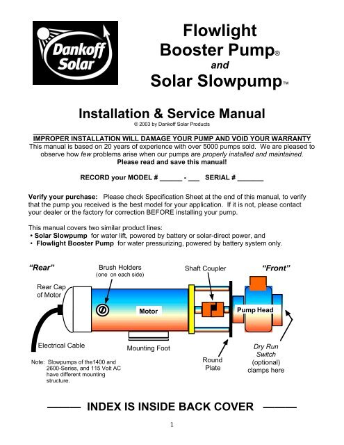
Conergy Slowpump Manual - Energy Matters
METHOD STATEMENT FOR INSTALLATION OF WATER SUPPLY PUMP (HOT ...

Diagram for REVERSE-OSMOSIS-BOOSTER-PUMP - H2O Distributors

Universal Booster Pump Mounting Bracket - China Mounting ...
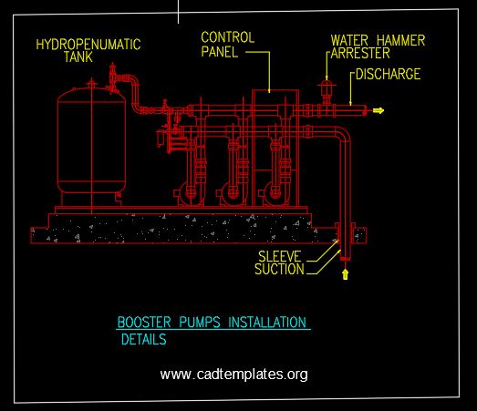
Booster Pumps Installation Details CAD Template DWG - CAD ...

ð’ð‘ðŠ ð„ð§ð ð¢ð§ðžðžð«ð¢ð§ð ð‚ð¨ð§ð¬ð®ð¥ððšð§ðœð² ...

Pin on Repair

Electric Porsche: Brake Booster Pump Installation
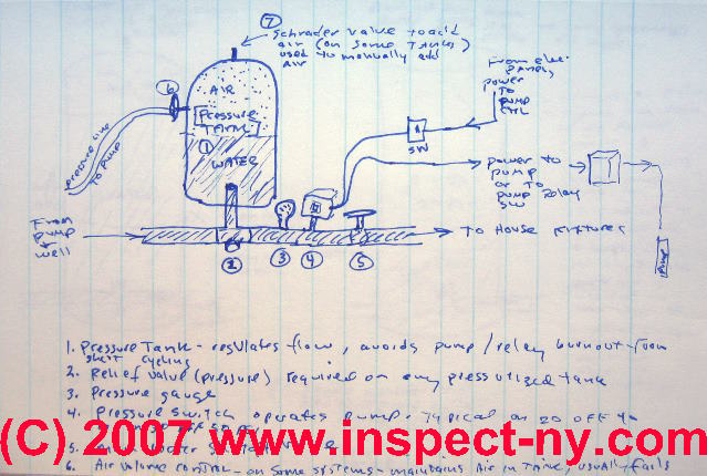
How to Find & Adjust or Repair the Water Pump Pressure ...
Booster water pump electric installation and plumbing details ...

Reverse Osmosis Exploded Diagram with Booster Pump | Reverse ...

Buying Guide - Storage Water Heater - JOVEN Home Appliances

Jet Pumps / Centrifugal Pumps Installation shallow well or ...
Buy boosting pumps for cold water supply. Boost pumps and ...
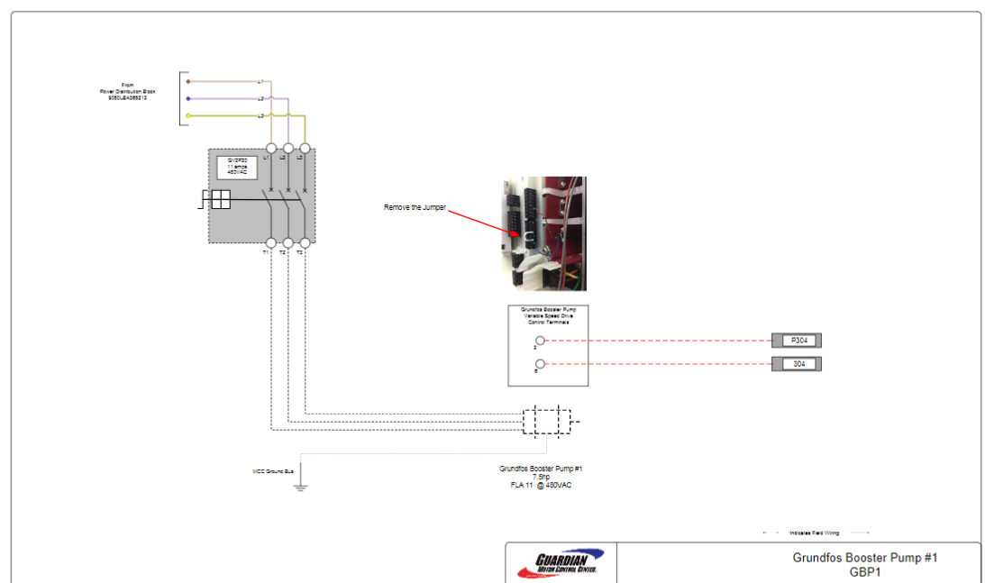
Wiring: Grundfos Booster Pump – Tommy Car Wash Systems

Primo Pumps - Davey HS Pumps
Packaged Pressure Booster Systems
RO Booster Pump DP-125 24VDC for water filter, pump penapis ...

What is a Booster Pump? | How does a Water Pressure Pump work?

WECO Economy Booster Pump Retrofit Kit for Reverse Osmosis ...


Comments
Post a Comment