43 pitot static system diagram
Cessna 172: Composed of a heated Pitot tube on the lower surface of the left wing. An external static port is located on the lower left side of the forward fuselage. Pitot Tube consists of a heating element, a 5-amp switch/breaker, and associated wiring. Alternate static (below throttle) provides pressure from inside the cabin. An aircraft pitot-static system comprises a number of sensors which detect Diagram of a pitot-static system including the pitot tube, pitot-static. The pitot tube is utilized to measure the total combined pressures that are present when an aircraft moves through the air. Static pressure, also.
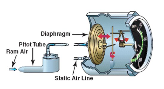
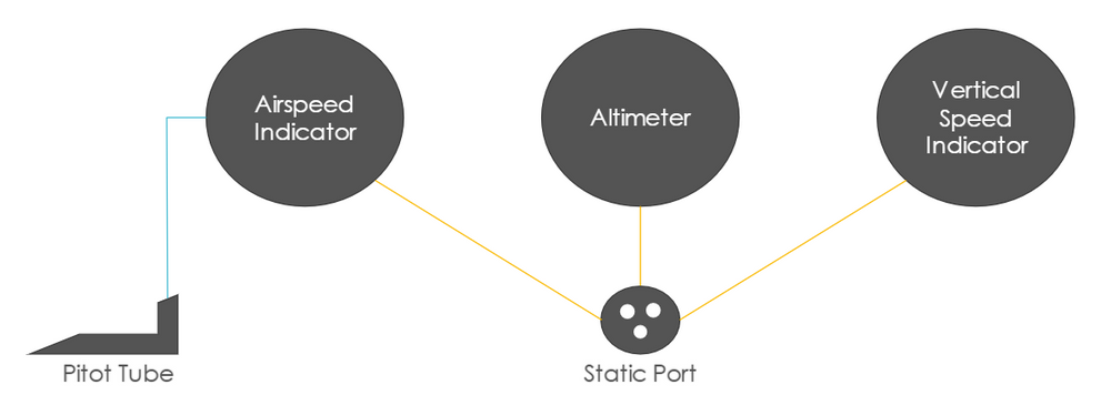
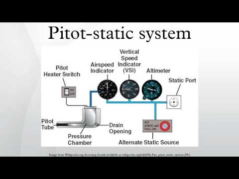
The pitot-static system includes a few components: a pitot tube and one or more static ports—which you've likely checked numerous times during the preflight inspection—and the associated lines that run from the pitot tube and the static ports to the airspeed indicator, vertical speed indicator, and altimeter.

Pitot static system diagram
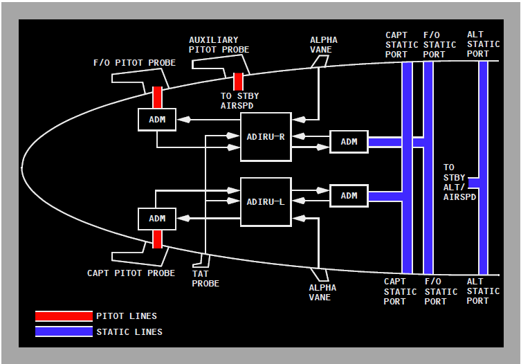
Pitot-Static System Installation Notes Some pitot static tubes are made with built-in heater elements. These are electrically powered and must be hooked to the electrical system. The pitot heat would then be controlled by an appropriately labeled instrument panel switch . . . but why a heated pitot-static tube if you don't fly IFR? The pitot-static system pressure lines and components are shown in a block diagram on Figure 1. PITOT HEADS Two pitot heads are mounted, one on each side of the fuselage nose and provide independent supplies of pitot pressure to the following: Left Pitot Head (P1) • Air Data Computer No. 1 Right Pitot Head (P2) • Air Data Computer No. 2 Pitot/static system for a small aircraft. 12-53. PITOT/STATIC TUBES AND LINES. The pitot tube (see figure 12-6) is in-stalled at the leading edge of the wing of a sin-gle-engine aircraft, outside the propeller slip-stream or on the fuselage of a multiengine air-craft with the axis parallel to the longitudinal axis of the aircraft, unless ...
Pitot static system diagram. Download scientific diagram | Pitot-static system and instruments II. MATERIAL & METHODS Altimeter The altimeter is an instrument that measures the height ... An aircraft pitot-static system comprises a number of sensors which detect Diagram of a pitot-static system including the pitot tube, pitot-static. The pitot tube is utilized to measure the total combined pressures that are present when an aircraft moves through the air. Static pressure, also. The heated pitot tube and static port are located underneath the left wing. An alternate static source is located inside the cabin under the left side of the instrument panel for use in the event of static port blockage. When using the alternate static source, the storm window and cabin vents must be closed, and the heater and defroster must be ... The kit consists of a pitot tube, static port and enough materials and supplies to connect the airspeed indicator, altimeter, and rate of climb to the pitot tube and static port. For an illustration of the basic components included in this kit, see Fig. 2.
The GDC 74A is the ADC for the system and receives the standard pitot and static system inputs as well as the outside air tempera-ture (OAT) input. This allows the system to automatically perform most E6B calculations, such as that of density altitude and true airspeed. Failure Mode(s) Diagram of a pitot-static system including the pitot tube, pitot-static instruments and static port These include: Altitude ( Altimeter) Airspeed ( Air Speed Indicator) Mach Number ( Machmeter) Vertical speed ( Vertical Speed Indicator ). Pitot and static pressure are also used in other equipment, such as the Autopilot and the Cabin Altimeter. The pitot static system is a network of pipes, sensors, and instruments that measure air pressure in different forms. These various measurements are displayed on calibrated instruments to provide meaningful data to the pilot. This data will include things such as: Altitude Rates of Climb and Descent Airspeed What is the pitot-static system? The pitot-static system is a pressure-based aircraft system that measures and compares ram air pressure and static pressure. That data is then transmitted to aircraft instruments in the cockpit, giving the pilot information on aircraft altitude, airspeed and vertical speed.
Diagram of a pitot-static system including the pitot tube, pitot-static instruments and static port Contents 1 Pitot-static pressure 1.1 Pitot pressure 1.2 Static pressure 1.3 Multiple pressure 2 Pitot-static instrument 2.1 Airspeed indicator 2.2 Altimeter 2.3 Machmeter 2.4 Vertical speed indicator 3 Pitot-static errors 3.1 System malfunctions SkyView system SkyView SE system (Hereafter, the EFIS-x and FlightDEK-D180 are referred to as "EFIS unit".) AOA/Pitot Probes and AOA products from Advanced Flight Systems, Inc. (AFS) The Dynon Avionics AOA/Pitot Probe (P/N 100141-000) is functionally equivalent to the AFS Pitot Probe Unheated - Underwing, P/N 44300. Jun 30, 2020 — An aircraft's pitot-static system measures total pressure and static pressure separately, from which dynamic pressure can be easily calculated ... This page shows a schematic drawing of a pitot tube. Pitot tubes are used on aircraft as speedometers. The actual tube on the aircraft is around 10 inches (25 centimeters) long with a 1/2 inch (1 centimeter) diameter. Several small holes are drilled around the outside of the tube and a center hole is drilled down the axis of the tube.
Articles - Pitot-Static System Blockages and Failures - Page 4
A pitot-static system is a system of pressure -sensitive instruments that is most often used in aviation to determine an aircraft's airspeed, Mach number, al...
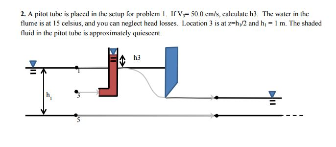
Solved: A Pitot Tube Is Placed In The Setup For Problem 1 ...
uh-1-75-16 11-75 pressurizing pitot / static system uh-1-75-18 11-75 tail rotor grip assembly 204-011-728-19 uh-1-75-19 11-75 incorrect part number on main servo uh-1-75-20 11-75 record keeping on servo's uh-1-75-21 12-75 tail rotor pitch change silent chain uh-1 76-01 01-76 kit b for ir suppressor

Pitot static system
AD FREE ANIMATIONSPLEASE SUBSCRIBE-DONATE请订阅和捐助Steve Karp Animation-illustration

Is it possible to detect a pitot static failure (blockage ...
The accuracy of a pitot-static system depends on many factors. One obvious one is that the nose of the aircraft may not point in exactly the same direction as the plane's motion. It could have a sideslip both vertically and horizontally. Also, the value static pressure can depend on where the static port is placed on the plane, and each ...

landscape photography of train passes on railway
AOA, Pitot, Static Installation Guide - Plumbing Kit 3 102708-000 Rev A Installation Static Port Static air pressure is obtained through both of the static port fittings provided by Dynon which will be mounted into the side of the aircraft. They should be mounted appropriately and in

Metrics, Signal Creation and Measurement
Pitot static system and instruments. The pitot-static system uses a heated total pressure (pitot) head mounted on the lower surface of the left wing, external static ports mounted on the left side of the forward fuselage and associated plumbing to connect the GDC 74A Air Data Computer and the conventional pitot-static instruments to the sources.

Pitot-static system - Wikipedia
The Pitot and Static Systems Tester is a pneumatic testing system that simulates aircraft airspeed from 0-400 knots; also be tested for leakage. The control panel of the Tester contains the three (3) appropriate aircraft instruments: Rate
Aerospaceweb.org | Ask Us - Types of Airspeed
PITOT-STATIC TEST SET INFORMATIONAL LETTER . The . Barfield 1811 series Pitot-Static Testers. are not advertised for use to comply with FAR 91.411. The Test Sets do fully meet the requirements of DOT Advisory Circular 43-203B for performing Altimeter and Static System Tests and Inspections. However, the personnel
CFI Brief: Pitot-Static Systems and Flight Instruments ...
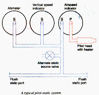
From our earliest days as student pilots, the instructor probably explained how pitot-static instruments work as well as the "plumbing." During my private checkride the examiner asked me to diagram the system and explain its operation. A Quick Review The pitot tube is only connected to the airspeed indicator, allowing ram air from the slipstream […]
Pitot Static System - QT
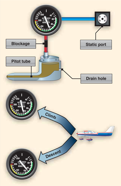
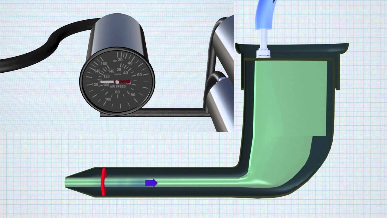
This is a diagram of a traditional pitot-static system using "steam gauges." Note the single static source and alternate static valve. The pitot system senses the pressure caused by the airplane moving through the air, which is vital to the airspeed indicator and the air-data computer if present.

white and brown house on green grass field during daytime
So, there is three flight instruments that ultimately use this pitot-static system – the airspeed indicator, the altimeter, and the vertical speed indicator.
CFII PTS - Technical Subject Areas: Aircraft Flight ...
Pitot-Static System Explained. In the diagram below you'll see how the ram air from the pitot tube and the static ports are connected to each of pitot-static system gauges. Attitude Indicator (Gyroscopic System) The Attitude Indicator, which is also sometimes called the "Artificial Horizon" gives the pilot a site picture of the aircrafts ...
1. Pitot-Static tube working principle | Download ...
RV- 7A Pitot Static system Installation Drawing. I am wanting to preview the Pitot Static system installation. Can someone share the Van's drawing associated with this kit? #2 01-23-2019, 08:40 AM BillL : Join Date: Sep 2007 ...
Pitot static system
21 environmental system 1f18 22 autoflight 1i6 23 communications 1i11 24 electrical power 1j3 25 equipment/furnishings 2a17 27 flight controls 2a24 28 fuel 2d10 32 landing gear 2e16 33 lights 2g8 34 navigation & pitot/static 2h14 piper aircraft pa - 2 8 - 1 8 1 airplane maintenance manual introduction page 6 reissued: july 30, 1994 1a6 island ...
Pitot static system
Pitot/static system for a small aircraft. 12-53. PITOT/STATIC TUBES AND LINES. The pitot tube (see figure 12-6) is in-stalled at the leading edge of the wing of a sin-gle-engine aircraft, outside the propeller slip-stream or on the fuselage of a multiengine air-craft with the axis parallel to the longitudinal axis of the aircraft, unless ...

black and gray speaker with blue light
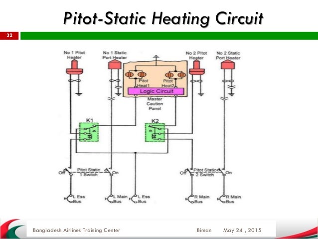
The pitot-static system pressure lines and components are shown in a block diagram on Figure 1. PITOT HEADS Two pitot heads are mounted, one on each side of the fuselage nose and provide independent supplies of pitot pressure to the following: Left Pitot Head (P1) • Air Data Computer No. 1 Right Pitot Head (P2) • Air Data Computer No. 2
Pitot-static system - YouTube
Pitot-Static System Installation Notes Some pitot static tubes are made with built-in heater elements. These are electrically powered and must be hooked to the electrical system. The pitot heat would then be controlled by an appropriately labeled instrument panel switch . . . but why a heated pitot-static tube if you don't fly IFR?

Top: diagram of a monoalveolar "lung" and airway ...

What is a Pitot Tube or Total Pressure Probe ...

5): Correction of Pitot-Static Tube Distance [38 ...

Our AME: Pitot Static System In Aircraft

Pitot-Static System Failures - Aviation Safety
Leeham News and Comment

Schematic of the pitot tube | Download Scientific Diagram
Pitot-static system | Wiki | Everipedia
Pitot Tube Working Principle Instrumentation Tools

What Happened to Air France 447? | Legal.com
How it Works Pitot-Static System - YouTube

1. Pitot-Static tube working principle | Download ...

Basic Flight Instruments Explained: The “Six Pack ...

black Sony Xperia android smartphone

Pitot Static Tube Diagram
How is a stagnation point created at the tip of a pitot ...

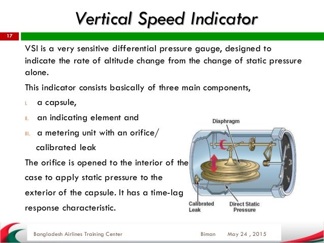
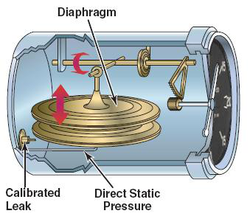
Altimeter Vertical Speed Indicator (VSI) The VSI, which is ...

Instrument, Elektrik Dan Radio Pesawat Terbang: PITOT ...

Hindusthan Institute Of Technology: Pitot-Static Tube
Pitot static system

Pitot Static System
Typical stagnation, Pitot and static pressure traces (the ...

stars during nighttime

Pitot Static System ~ Electronic Note

Pitot Static System and Transponder Tests - Firkus Aircraft

Metrics, Signal Creation and Measurement


Comments
Post a Comment