39 intermatic timer wiring diagram t101
T101 Technical Data Sheet. 24-Hour Mechanical Time Switch, 120 VAC, 60Hz, SPST, Indoor Metal Enclosure, 1 Hour Interval ... Wiring Option: Terminals: Resistive Load Ratings Ranges: 40 A, 120-240 VAC, 60 Hz: Warranty Period: ... Intermatic T100 Series Mechanical Time Switches Deliver Long-Lasting Value. Watch Video. Products. Timer Controls ... Chip Hosting Solutions. Hosting and Consulting for All. Navigation Menu. Navigation Menu
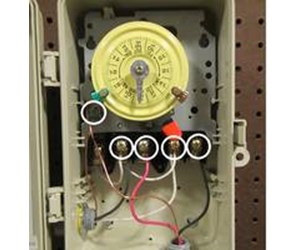
Intermatic Incorporated manufactures timer switches designed for indoor and outdoor use. Many pool pump motors and water heaters use Intermatic timers to regulate their run times. An Intermatic timer-switch saves electricity when it turns a water heater off at night and when it limits the amount of time a pool's filtration system runs.
Intermatic timer wiring diagram t101
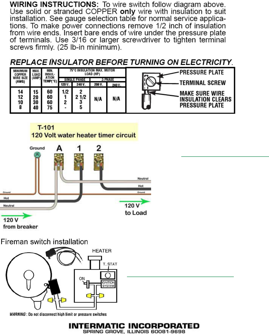
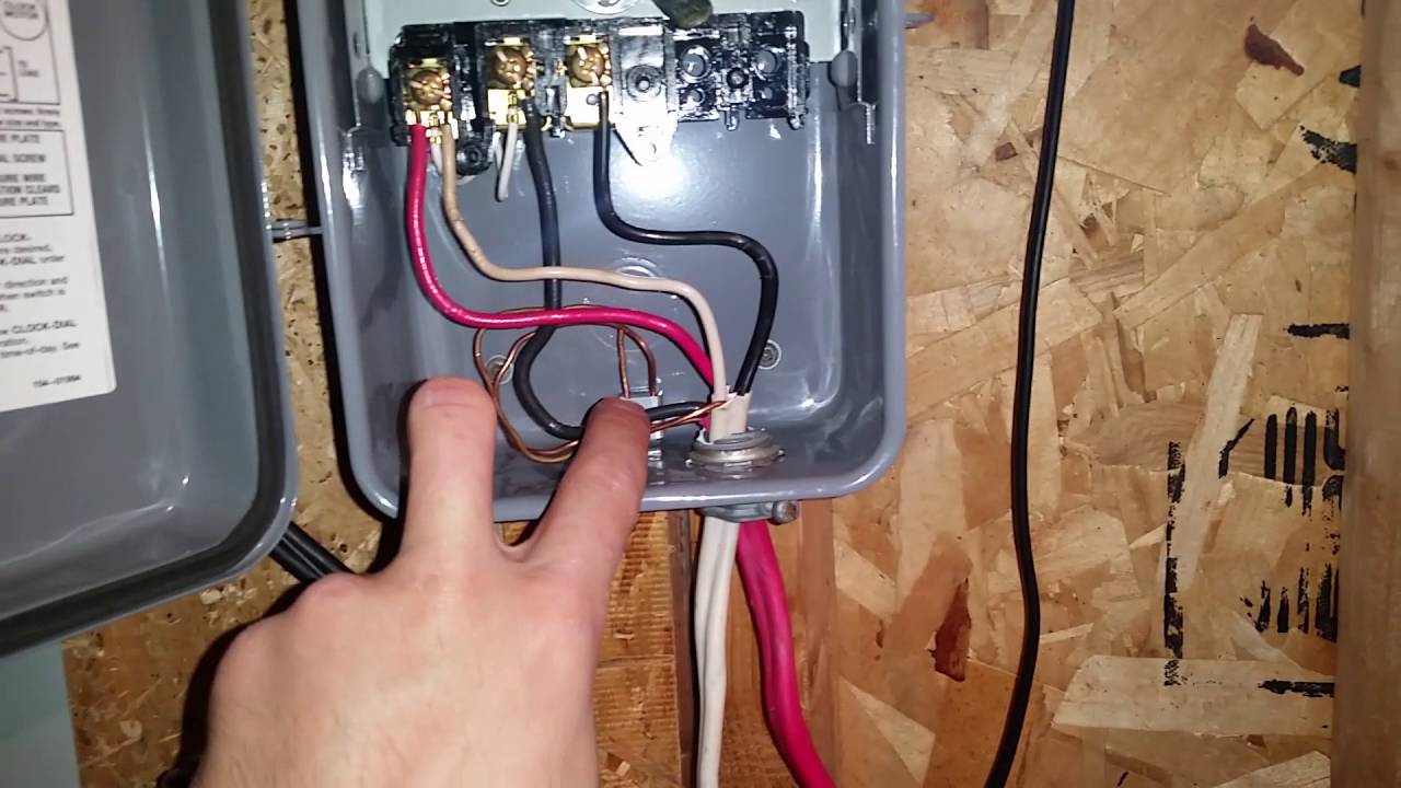
WIRING INSTRUCTIONS: To wire switch follow diagram above. Use solid or stranded COPPER only wire with insulation to suit. Intermatic etc time switches: user guide (20 pages) Switch Intermatic ET SERIES Owner/installer Instruction Manual. intermatic incorporated ts spring grove, illinois time pointer time dial off tripper manual lever on tripper ... Intermatic et1125c 24 hour 30 amp electronic time switch 120 277 vac nema 1. Fan timer switch wiring diagram. Need help wiring an intermatic. Electrical wiring diagrams diy timer switch wiring diagram that are in color have a benefit about types that are black and white only. Potential free designed for the control of any electrical installation. Check out the diagram below, or see the wiring diagram which comes with a new timer, or is printed on the door of the timer box. After securing the wire conduit (flexible or rigid) to the box knock out with the proper 3/4″ conduit connector, first secure the green ground wire to the green ground screw, shown as GR.
Intermatic timer wiring diagram t101. Intermatic T101 Timer Wiring Diagram. By Admin | December 13, 2017. 0 Comment. How to connect intermatic t101 timer with diagram t104r won t turn pump on but does it off doityourself com community forums t101p201 instruction manual changing in wall clueless determined diy home improvement forum troubleshooting pool multimeter i just finished ... Intermatic T101 Timer Wiring Diagram - Wiring Diagram Top wiringdiagram.2bitboer.com. Intermatic 30 Amp 7 Day Spst 1 Circuit Astronomic Time Switch Et8015c The. How to connect intermatic t101 timer mechanical time switch t104r won t turn pump on … 489 People Learned More Courses ›› Energy Controls www.intermatic.com Diagrams T100 Series Specification The time switch shall be of the 24-Hour dial type, capable of permitting up to 12 ON/OFF operations each day. The time switch shall provide a minimum ON/OFF time of 1 hour. The time switch shall be powered by _____ (125)(208-277) VAC,_____ (50)(60) Hz power supply. How to wire T timer. use wiring diagram above to control 3-pole contactor, or diagrams to left and . How to wire Intermatic T How to wire T timer. The T Series Mechanical Time Switch has proven it can stand the test of time. These dependable time switches can handle electrical loads up to 40 A per. This Pin was discovered by Fuyang Ke.
Dimension: 1500 x 1281. DOWNLOAD. Wiring Diagram Images Detail: Name: intermatic t103 wiring diagram - Intermatic cell Wiring Diagram Best 06 Intermatic Et1125 Intermaticring Diagram Timer T101 T103. File Type: JPG. Source: irelandnews.co. Size: 677.49 KB. Dimension: 1280 x 1641. DOWNLOAD. intermatic timer manual t101 intermatic timer manual t101. intermatic timer manual t101 07 Feb. intermatic timer manual t101. Posted at 10:48h in how much is a 1955 chevy bel air worth by direct hiring, factory worker in caloocan Likes ... · Model T101.Intermatic t101 timer wiring diagram dual time clock for t104 t102 pool on pump audi st01 89 town car fuse box 120 volts model water heater dayton timing relay t103 supplementary manual microwave mechanical woods 59008 full switch ej500 wire 240 volt t104r light 277 toggle solenoid diagrams with honda hr v deutsch push pull. Depending on how the timer is switched internally, if you look at the wiring diagram the jumper wire between terminals 2 and 3 are carrying the 120v to terminal 3 regardless if the timer is on or off. This may be fine for a 120v circuit, however it is not safe to do on a 240v circuit, unless the timer does not carry voltage to that #3 terminal when it is on.
Under a minute vid showing how to wire these timers (110/120V model) The Intermatic T101R mechanical timer is an easy-to-use device for automatically controlling lights, pool pumps or any other load that you want to switch on and off at set times each day. The T101R can be set to switch a load on and off up to 12 times a day, using color-coded pegs inserted into the timer wheel. How to connect Intermatic T101 timer (with diagram) - Answered by a verified Electronics Technician We use cookies to give you the best possible experience on our website. By continuing to use this site you consent to the use of cookies on your device as described in our cookie policy unless you have disabled them. Timer wiring
Guidance needed for wiring of pool pump timer bypass in 240V ...
by Vallery Masson updated on August 4, 2021. May 23, 2021 on Intermatic Pool Timer Wiring Diagram. A wiring diagram is a type of schematic which utilizes abstract pictorial signs to reveal all the interconnections of components in a system. A pool pump timer interrupts the electric circuit powering the pump motor during off use periods.

SOLVED: How do i wire a t104p102 intermatic time switch ? - Fixya
Indoor Steel Case - Gray Finish - 120-277 Volt - Intermatic ET1125C. Images. ×. Images. Video. These Intermatic time switches provide the same performance as the T101 mechanical time switch, as well as to-the-minute programming for accurate load control and reduced energy costs. Auto daylight savings time adjustment. 28 set points (14 ON/14 OFF)

troubleshooting pool timer with multimeter - DoItYourself.com ...
WIRING DIAGRAM WARNING Risk of Fire or Electric Shock ... Gain 24 hour control over loads up to 40 amps with the intermatic T101 dial switch. Find affordable 24 hour dial time switches at 1000Bulbs.com! Keywords: intermatic t101, 078275000018, 24 hr. dial time switch, intermatic timer switches, 24 hour time switch, intermatic 24 hour time ...

9 24 hour timer switch ideas | timer, switch, switches
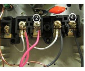
proper time-of-day. see programming instructions. intermatic incorporated 158ts10941 spring grove, illinois 60081-9698 time pointer time dial off tripper manual lever on tripper clock motor ground a 1 2 grd. 120v supply to line load neut. wiring diagram pressure plate terminal screw make sure wire insulation clears pressure plate minimum copper ...

Forward Reverse Star... - Md.Imran Khan—R/ac-Technician ...
city of redmond plumbing permit highest subway surfer score without keys zesco managing director salary intermatic t101 timer replacement. intermatic t101 timer replacement. by . Jul 2, 2022. stairmaster trail moab ...
Changing In-Wall Timer - Clueless but Determined | DIY Home ...
Mechanical Time Switches. Manage everyday load control needs with industry-leading mechanical time switches from Intermatic. Reliable and low maintenance, these solutions are an ideal choice to pair with water pumps, lights, fans, water heaters and other electrical loads.
How To Install an Intermatic T104 Timer - INYOPools.com
How to wire 4 outlets to 1 INTERMATIC T101 SPST timer [ 1 Answers ] I am new "Electrican". I did follow the instruction to out 1 set of 4 wires together in 1 INTERMATIC T101 40AMP 2 HP 120V timer, but the timer does not work. While all 4 swtiches for 4 set of lighting work fine.
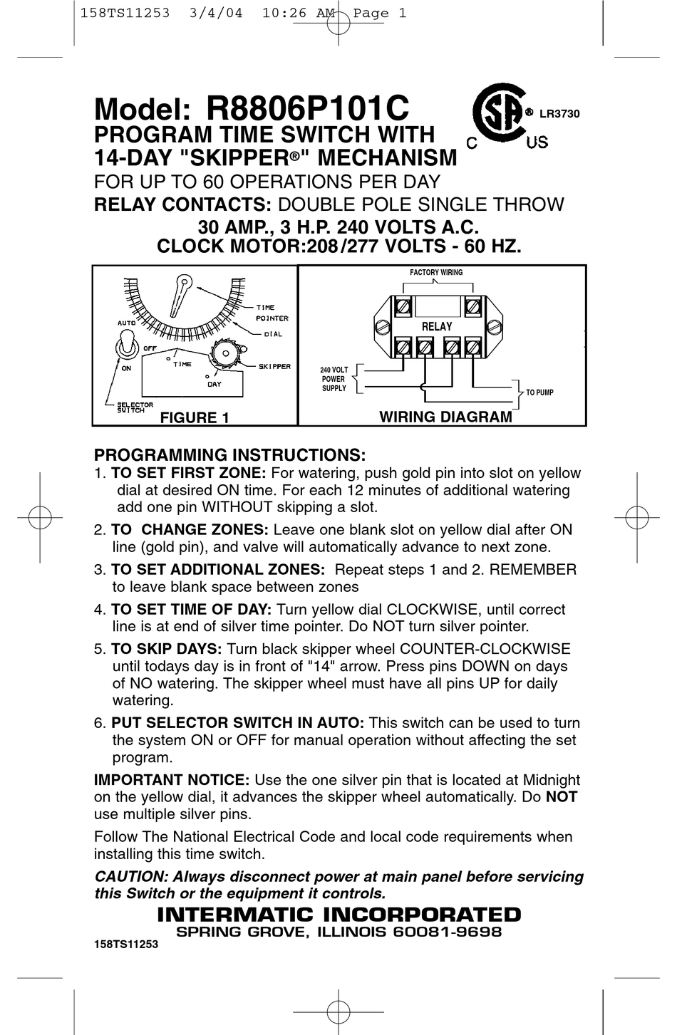
INTERMATIC R8806P101C SWITCH SUPPLEMENTARY MANUAL | ManualsLib
Intermatic pool timer wiring t104r won t turn pump on an wh40 water heater diagram how to connect t101 white ei200w electronic timers instructions operating r8806p101c supplementary p1353me manual wall digital switch t104 off t106r 24 hour dial et1105 outlet in lighting intelliflo vs whisperflo e1020 installation et1705c owner s reviews.

How to wire T101 timer
Intermatic T101 Timer Wiring Diagram. 02.09.2018 02.09.2018 4 Comments on Intermatic T101 Timer Wiring Diagram. do you have a diagram on how this is wired? Open following link for T wiring: schematron.org#T should be fine, here is a link to the wiring diagram for the timer.

SOLVED: Intermatic t1202T 240v dual pool timer. Main - Fixya
Intermatic T101 Supplementary Manual. How To Install an Intermatic T Timer A major difference between the T and T timers that you have to consider is the timer motor. The T runs on V; the T runs on V. In the wiring diagram is says neutral.. when I connect it to the white neutral bar in the fuse box it trips the gfi same if I connect it to the ...

troubleshooting pool timer with multimeter - DoItYourself.com ...
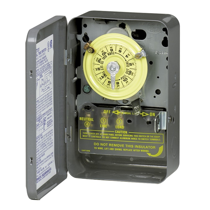
INTERMATIC MODEL T101 TIME SWITCH single pole. INTERMATIC Outdoor Lighting $29.95. Intermatic T101 Electromechanical Timer, 208-277 V, 40 A, 1-23 Hr, 1-12 Cycles P 4.5 out of 5 stars (94) 94 product ratings - Intermatic T101 Electromechanical Timer, 208-277 V, 40 A, 1-23 Hr, 1-12 Cycles P Timer dial must be reset after power outage.
Wiring an Intermatic Wall Timer in a three way switch | DIY ...
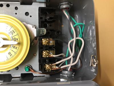
Check out the diagram below, or see the wiring diagram which comes with a new timer, or is printed on the door of the timer box. After securing the wire conduit (flexible or rigid) to the box knock out with the proper 3/4″ conduit connector, first secure the green ground wire to the green ground screw, shown as GR.

TIMERS
Intermatic et1125c 24 hour 30 amp electronic time switch 120 277 vac nema 1. Fan timer switch wiring diagram. Need help wiring an intermatic. Electrical wiring diagrams diy timer switch wiring diagram that are in color have a benefit about types that are black and white only. Potential free designed for the control of any electrical installation.
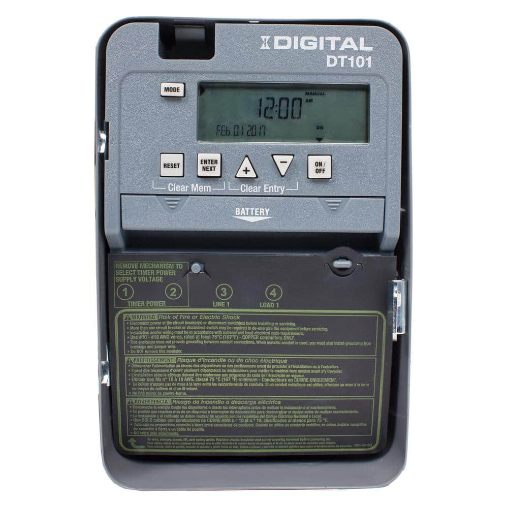
Intermatic DT Series 1-Circuit 20 Amp 24 Hour Indoor Surface Mount Timer with Battery Backup, Gray DT101D89 - The Home Depot
WIRING INSTRUCTIONS: To wire switch follow diagram above. Use solid or stranded COPPER only wire with insulation to suit. Intermatic etc time switches: user guide (20 pages) Switch Intermatic ET SERIES Owner/installer Instruction Manual. intermatic incorporated ts spring grove, illinois time pointer time dial off tripper manual lever on tripper ...

Intermatic T104R won't turn pump on, but does turn it off ...
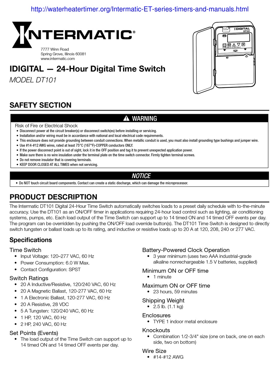
INTERMATIC DT101 MANUAL Pdf Download | ManualsLib

How to wire Intermatic T104 and T103 and T101 timers

T101 - 40A 120V SPST Metal Indoor Time Clock
Intermatic T101P201 instruction manual

Quiet replacement for Intermatic mechanical timer switch : r ...

Need help wiring new intermatic timer. The old one bit the ...
Intermatic 1-Outlet In-Wall Lighting Timer
Have you or anyone you know ever experienced an electric ...
Intermatic Pool Timer Troubleshooting - InTheSwim Pool Blog

Intermatic Pool Timer Troubleshooting - InTheSwim Pool Blog

How to wire Intermatic T104 and T103 and T101 timers

main | 24-Hour Mechanical Time Switch, 120 VAC, 60Hz, SPST ...
Intermatic 40-Amp 1-Outlet Mechanical Residential Hardwired ...

How To Install an In-Line Salt Chlorine Generator - INYOPools.com

main | Astronomic 7-Day 1-Circuit Electronic Control, 120-277 ...

Help - Replace Intermatic Timer with Smart switch to control ...
How To Replace an Intermatic T104 Clock Motor - INYOPools.com

Intermatic T104 | Timer, Swimming pools, Swimming

Question about wiring two different brand of timers ...

How to replace your mechanical time clock

Intermatic Pool Spa Time Switches Controls timers

How to wire T101 timer
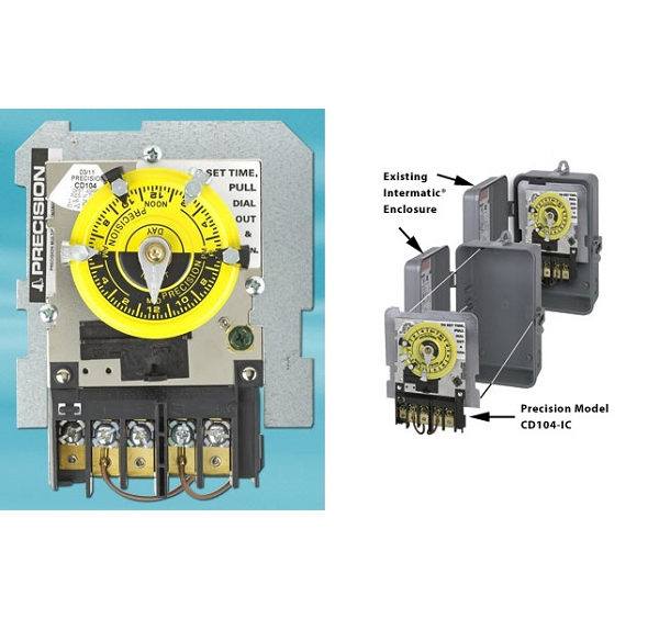
Precision Direct Timer Replacement Series
How To Wire and Connect A Intermatic Pool Pump Timer - T101R


Comments
Post a Comment