39 Lathe Axis Diagram
PDF Lathe - University of Michigan axis position is measured by means of rotating encoder emitting 1000 pulses per revolution, of which 125 are utilized in ordinary operation. Therequired accuracyis 1 pulse, equivalentto 0.01 mm. I. GENERALDESCRIPTION AGENERAL block diagram of the proposed system is shown in Fig. 1. Two control units, one for each axis, are connected to the ... The 8 Parts of a Lathe Machine (With Diagram) - Woodwork ... A lathe machine is a machine tool that serves one very basic, but very broad, purpose: rotating a workpiece all around a fixed axis that holds a tool bit. Rotating a workpiece around a fixed axis that contains a tool bit allows for a number of different functions to be performed.
PDF DIGITAL DIGITAL READOUTREADOUTREADOUT Operation Manual as shown in the following diagram. Or Key and enter the coordinate number directly. Enter the number Key digit keys, such as 6.66..6. Centering FunctionCentering Function ... Radius/Diameter mode on lathesmode on lathesmode on lathes. ... X axis datum on the center line. 1) Cutting tool in position A. 2) Key

Lathe axis diagram
X, Y, Z On A Lathe - The Hobby-Machinist 'The axis parallel to the spindle axis is always Z, whether its a mill or lathe. And, for the lathe, the axis that controls the diameter is always X.'' Does that mean the 'up and down' adjustment when using a milling attachment on the lathe is the Y axis? Terrywerm Registered. Registered. Joined Jan 16, 2020 Lathe machine - The ultimate guide for beginners In a lathe machine, the job is held between two centers. These centers support the job and hold it firmly in place. The job needs to be held down securely. The job rotates about its own axis. The cutting tool is placed on the tool post. (Check out the diagram for a four-way tool post below.) PDF Lathe Programming Workbook - Haas Automation The diagram at left shows a front view of the grid as it would appear on the lathe. This view shows the X and Z axes as the operator faces the lathe. Note that at the intersection of the two lines, a common zero point is established. The four areas to the sides and above and below the lines are called "QUADRANTS" and
Lathe axis diagram. 4 Axis CNC Machining in 2021: The Definitive Guide 4th Axis + Lathe Chucks. For round parts, and for many things that go 'round, lathe tooling is where its at. After all, it's optimized to do workholding along a rotating axis. Hence, it's very common to mount lathe chucks on your 4th Axis: Machining a gear with a 4th axis… PDF Block Diagram Model of Lathe Machine - WSEAS The derived model consist of the controller, axis drive and the spindle drive of a CNC turning machine and their connection through the cutting process. The overall model uses a modular multi-model approach to prototype the machine tool and its process. Keywords: Block-diagram, Lathes, modelling, simulation, dynamic 1 Introduction Lathe Machine: Definition, Parts, Types, Operation ... The distance between the lathe axis and the lathe bed is called the height of the center. c) Swing Diameter over the bed: It is the maximum diameter of the workpiece that can we turned on a lathe without hitting the lathe bed. d) Maximum bar diameter: It is the maximum diameter of the workpiece that can be passed through the hole in the headstock. Definition of each lathe axis - Practical Machinist The axis parallel to the spindle axis is always Z, whether its a mill or lathe. And, for the lathe, the axis that controls the diameter is always X. C is the most common on a Lathe, as it relatively easy to turn the chuck into a C axis. Yes, Z and X are what I've heard the most of in the manual world.
Y-Axis Lathes - Haas Automation Haas Y-axis lathes combine ±2" of Y-axis travel, full C-axis motion, and high-performance live tooling to create versatile done-in-one machining solutions for any shop. Easily perform secondary milling operations on your lathe - such as off-center milling, drilling, and tapping - to boost throughput and increase accuracy. Lathe Machine - All Parts And Functions With Diagrams And Uses Lathe Machine. The removal of material from metal is called Machining, and the process usually happens in a machine shop that has special equipment.. Parts of lathe machine Headstock: The headstock is fixed on the machine and it consists of many pulleys, lever, spindle, chuck, and gear box. Identifying Parts of a Lathe Machine (with Illustrated ... Here is a diagram with all the important parts of a lathe machine. There are six major parts of a lathe machine. These are the bed, the head stock assembly, the main spindle, the tail stock, the carriage, and overload safety devices. Let's take a closer look at each main part. The foundation of the lathe machine where its various operational ... (PDF) Block Diagram Model of Lathe Machine - Academia.edu Block Diagram Model of Lathe Machine M EBRAHIMI, W MOUGHITH AND J VICTORY School of Engineering University of Bradford, West Yorkshire, UK Abstract: This paper presents a computer aided method for the analyses and simulation of a non-linear mathematical model of a CNC Lathe machine tool. The derived model consist of the controller, axis drive ...
4-axis lathe, 4-axis turning center - All industrial ... vertical 4-axis for shaft machining. CNC turning center. VTC 100. Diameter: 0 mm - 160 mm. Spindle speed: 0 rpm - 6,000 rpm. The VTC 100- 4 is a four- axis vertical turning machine. It has a main spindle in the central part of the upper section with a tailstock on the bottom. The shafts are made with a main spindle ... PDF Axis Designation in Nc Part Programming considered an axis only when controlled from tape / cd instructions and having open loop or closed loop drive. how to define an axis. 5. caretsian co -ordiante system for designating main axes of nc m/t two axes vertical lathe. how to define an axis. 6. Basic Lathe Operations | Lathe operation Explained Basic Lathe Operations | Lathe operation Explained. Lathe is a machine tool which causes workpiece to revolve so that when cutting tool comes in contact with the workpiece it removes the metal in the form of chips. Workpiece can be held securely and rigidly on the machine tool between centres or by means of chuck. Diagram of a Lathe with explanantion of components DIAGRAM OF LATHE MACHINE. Explanation of the standard components of most lathes: • Bed: Usually made of cast iron. Provides a heavy rigid frame on which all the main components are mounted. • Ways: Inner and outer guide rails that are precision machined parallel to assure accuracy of movement. • Headstock: mounted in a fixed position on ...
Find Cnc Lathe & A366-11 / B366-11 High Efficiency Double ...
Lathe Machine-Introduction,Working Principle,Parts ... Bench lathe is a small lathe usually mounted on a bench. This is using for small and precision work. 2. Speed lathe machine. Speed lathe is the simplest of all types of lathe in construction and operation. It consists of a bed , a head stock, a tail stock and a tool - post mounted on an adjustable slide. The spindle speed is about 4000 rpm.
An Introduction to Mill-Turn Technology
PDF Lathe Machine: Definition, Introduction, Parts, Operation ... Schematic diagram of the lathe machine: Lathe machine tool Now discuss the operations performed in a Lathe 5/19. Here is the comprehensive list of lathe operation. Although as any operation ... with lathe axis. 2. Hold the cutting tool on the tool post and set the cutting edge at the job axis or slightly above it. 3. Set the spindle as per ...

CNC | Work Coordinate System - Cnc Code questions and answers ...
CNC Milling Machine Axis Explained [Complete DIY Guide ... CNC Milling Machine Axis Explained [Complete DIY Guide] [ CNC Milling Machine Parts Home] A CNC Milling's Axes are attached to the Machine Frame.. Their role is to provide motorized motion in each dimension as commanded by the control panel or g-code program through the controller.
CNC Lathe Resources
Vertical Cnc Milling Machine Diagram Vertical Cnc Milling Machine Diagram - Factory, Suppliers, Manufacturers from China. We support our consumers with ideal good quality merchandise and large level provider. Becoming the specialist manufacturer in this sector, we have attained wealthy practical encounter in producing and managing for Vertical Cnc Milling Machine Diagram, Cnc ...

Axis Designation for CNC Machine (3D Animation)
PDF Lathe machine specification with diagram Lathe machine specification with diagram Do £ the slats to be confused with a thin wooden pedaço. For other uses, see around (desambiguaçà £ o). máquinas tool that turns the work Used Parts on its axis This article has vários problems. Please help improve it or discuss these problems on the discussion page.
NX 12 CAM - How to tilt tool in 4 axis, but output Gcode in ...
All Parts of Lathe Machine | Lathe Machine Diagram ... All Parts of Lathe Machine. A lathe machine is a machine tool used to rotate various workpieces about one axis to perform operations like facing, turning, cutting, taper turning, knurling, drilling, etc to make a finished object. In a lathe machine, various individual parts are contributing or in action to give you a finished product.
CNC Swiss Lathes | Used Screw Machines | Graff-Pinkert.com
CNC Lathe Series Training Manual Haas TL Series Tool Room ... Productivity Inc Haas CNC TL Series Lathe Operator Manual Page 4 The Cartesian Coordinate System The first diagram we are concerned with is called a NUMBER LINE. This number line has a reference point zero that is called ABSOLUTE ZERO and may be placed at any point along the line. Fig-1 - 1 Horizontal number line Z Axis
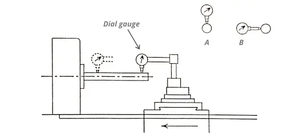
Lathe Alignment Test (A Short and Simple Guide)
PDF Lathe Series Training Manual Haas CNC Lathe Programming Productivity Inc - Haas Lathe Programming Manual Page 8 X Axis The diagram above shows the operator's view of X and Z grid standing in front of the lathe. At the intersection of the X and Z axis is the Part Zero or Reference Point. Note there is four different quadrants with different positive and values for X and Z.

China 5 axis 380V/12KW citizen Swiss CNC lathe machine price ...
Instruction and Parts Manual - Summit Machine Tool Summit Machine Tool, 518 N Indiana Ave Oklahoma City, OK 73106. Toll Free: 800-654-3262 Local: 405-235-2075 Fax: 405-232-5169

CNC turning machine - MSY-Ⅱ series - Tsugami - 3-axis ...
Lathe Machine (PDF): Definition, Parts, Types, Operations ... The "T -lathe" is used for machining rotors for jet engines. The axis of the lathe bed is at right angles to the axis of the headstock spindle in the form of a T. CNC Lathe Machine: CNC stands for Computerized numerically controlled. This is widely used as a lathe in the present time because of its fast and accurate working.

CNC Program Block - Helman CNC
Lathe Machine Operations [Complete Guide] with Picture & PDF 3. Conclusion: A lathe is a machine that rotates the workpiece about an axis to perform different operations such as turning, facing, taper turning, knurling, grooving, parting off, thread cutting, reaming, etc. Let's discuss all lathe machine operations one by one as follows. To perform different lathe machine operations on a lathe, the ...
![Workspace with axis [5] | Download Scientific Diagram](https://www.researchgate.net/profile/Matus-Beno/publication/265179362/figure/fig2/AS:295849839087629@1447547506897/Workspace-with-axis-5_Q320.jpg)
Workspace with axis [5] | Download Scientific Diagram
PDF Lathe Programming Workbook - Haas Automation The diagram at left shows a front view of the grid as it would appear on the lathe. This view shows the X and Z axes as the operator faces the lathe. Note that at the intersection of the two lines, a common zero point is established. The four areas to the sides and above and below the lines are called "QUADRANTS" and
CNC Milling Machine Axis Explained [Complete DIY Guide ...
Lathe machine - The ultimate guide for beginners In a lathe machine, the job is held between two centers. These centers support the job and hold it firmly in place. The job needs to be held down securely. The job rotates about its own axis. The cutting tool is placed on the tool post. (Check out the diagram for a four-way tool post below.)

Methods of shaping polygons on universal CNC lathes, a) plain ...
X, Y, Z On A Lathe - The Hobby-Machinist 'The axis parallel to the spindle axis is always Z, whether its a mill or lathe. And, for the lathe, the axis that controls the diameter is always X.'' Does that mean the 'up and down' adjustment when using a milling attachment on the lathe is the Y axis? Terrywerm Registered. Registered. Joined Jan 16, 2020

Lathe machine - The ultimate guide for beginners
CNC Turning Basics
CNC Turning and CNC Turning Center Basics

Lathes - an overview | ScienceDirect Topics

Structural layout of four-axis ultra-precision drum lathe ...

MEA Parthivi - DIAGRAM OF LATHE MACHINE Explanation of the ...
Important User Concepts

Star GB - The SR-20JII Type B CNC Sliding Head Lathe
CNC Lathe Jib Adjustment
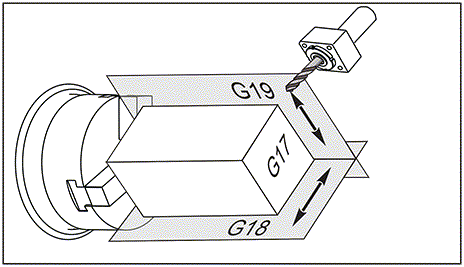
G17 XY / G18 XZ / G19 YZ Plane Selection (Group 02)
Chp 02-01 Numerical Control Programming
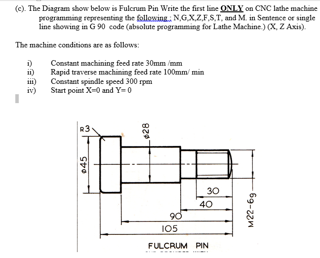
Solved (C). The Diagram show below is Fulcrum Pin Write the ...
Tool path generation of turning optical freeform surfaces ...

Lathe Machine (PDF): Definition, Parts, Types, Operations ...
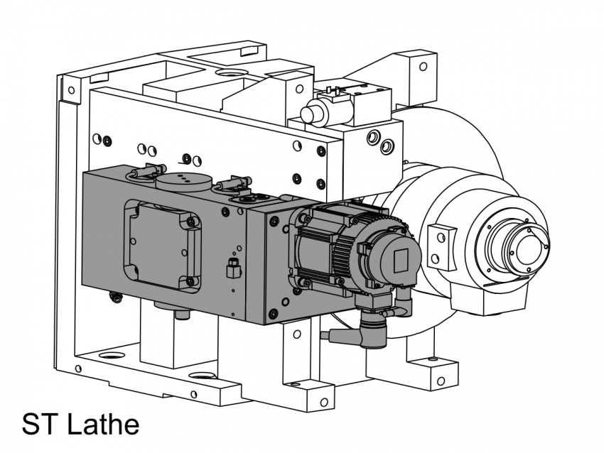
C Axis - Gear Mesh Contact - Load Adjustment - ST - SL

What is Lathe Machine? Main parts, Operations and Working ...

How many axis are in a CNC lathe? - Quora

Siemens CNC Lathe | Cycle95 Example | Z axis Parallel Cutting ...

lathe-diagram - ijohnsen.com Info...

How Does a CNC Swiss-Type Lathe Work & Why is It Useful ...

CNC Lathes—What You Need To Know - Hwacheon Asia Pacific Pte ...
Chp 02-01 Numerical Control Programming

CNC Lathe Router Rotary Rotational Axis A-axis 4th-axis 3Claw ...
Lathe Series Training Manual Haas CNC Lathe Programming

XYZ Axis 600*900*80mm Spindle Clamp 80mm Engraving Machine ...


Comments
Post a Comment