39 Pure Sine Wave Inverter Circuit Diagram Free Download
tahmidmc.blogspot.com › 2013 › 01Using the SG3525 PWM Controller - Explanation and ... - Blogger Jan 07, 2013 · i want 250 watt 220v 50 hz pure sine wave circuit diagram ... .i have done 12v to 310 v circuit and i want circuit diagram of H-bridge to produce 220 v , 50 hz pure sine wave ...thank you very much. Delete PDF Sine Wave Inverter Circuit Diagram - jobs.ocala.com Download File PDF Sine Wave Inverter Circuit Diagramchecking out a books sine wave inverter circuit diagram after that it is not directly done, you could take even more roughly ... LC filter to make pure sine wave inverter circuit diagram. sine wave inverter circuit digram with code The following is a high efficiency sine Page 12/36.
Pure Sine Wave Inverter Schematics Free !NEW! ⚡ - Coub Coub is YouTube for video loops. You can take any video, trim the best part, combine with other videos, add soundtrack. It might be a funny scene, movie quote, animation, meme or a mashup of multiple sources.

Pure sine wave inverter circuit diagram free download
PDF Sine Wave Inverter Circuit Diagram - video.gadsdentimes.com Online Library Sine Wave Inverter Circuit Diagram Sine Wave Inverter Circuit Diagram Yeah, reviewing a ebook sine wave inverter circuit diagram could increase your close connections listings. This is just one of the solutions for you to be successful. As understood, capability does not suggest that you have wonderful points. PDF Sine Wave Inverter Circuit Diagram - health.savannahnow.com Get Free Sine Wave Inverter Circuit Diagram harmful virus inside their computer. sine wave inverter circuit diagram is approachable in our digital library an online entry to it is set as public in view of that you can download it instantly. Our digital library saves in merged countries, allowing you to get the most less latency period to ... (PDF) Physics English Part 2 new | Ankit Sharma - Academia.edu Download Free PDF. Download Free PDF. Physics English Part 2 new. 448 Pages. Physics English Part 2 new. Ankit Sharma. Download Download PDF. Full PDF Package Download Full PDF Package. This Paper. A short summary of this paper. 8 Full PDFs related to this paper. Read Paper. Download Download PDF. Download Full PDF Package ...
Pure sine wave inverter circuit diagram free download. Sine Wave Inverter Circuit Diagram - insys.fsu.edu sine-wave-inverter-circuit-diagram 1/1 Downloaded from insys.fsu.edu on February 12, 2022 by guest [DOC] Sine Wave Inverter Circuit Diagram This is likewise one of the factors by obtaining the soft documents of this sine wave inverter circuit diagram by online. Electric power system - Wikipedia An electric power system is a network of electrical components deployed to supply, transfer, and use electric power. An example of a power system is the electrical grid that provides power to homes and industries within an extended area. The electrical grid can be broadly divided into the generators that supply the power, the transmission system that carries the power from the … PDF Digital Sine Wave Ups Circuit Diagram digital sine wave ups circuit diagram free pure sine wave ups reference design from microchip. how to build a high eifficiency modified sine wave inverter. 100 watt inverter circuit diagram parts list amp design tips. sine wave oscillator circuit oscillator circuits next gr. 1000w inverter pure sine wave schematic diagram power. Homemade 2000w power inverter with circuit diagrams - GoHz Here is the circuit section, get understanding the basics of this power inverter, DIY an inverter now. Forward board DC-DC power circuit board, conventional push-pull. ( Download PDF file) Forward DC-DC circuit driver schematic. It has undervoltage, overvoltage, overcurrent protection, overcurrent protection is implemented by test tube drop.
› sg3525-pure-sinewave3 High Power SG3525 Pure Sinewave Inverter Circuits ... the inverter shown in the above daigram is a basic square wave design, in order to convert it to sine wave you must follow the steps explained below The mosfet gate/resistor ends must be configured with a BJT stage and the 555 IC PWM should be connected as indicated in the following diagram: Regarding Connecting parallel mosfets PDF Pure Sine Wave Inverter Circuit Using Pic sine wave inverter circuit diagram with complete step by step program and coding, In this article I will discuss how to use push pull converter, sinusoidal pulse width modulation, h bridge and low pass LC filter to make pure sine wave inverter circuit diagram. Pure Sine Wave Inverter Circuit Using Arduino To make the varying PWM signal, we are going to use the 16-bit timer1 with a prescaler setting of 1, which will give us 1600/16000000 = 0.1ms time for each count if we consider a single half-cycle of a sine wave, that fits exactly 100 times within a one-half cycle of the wave. In simple terms, we will be able to sample our sine wave 200 times. PURE SINE WAVE INVERTER PROJECT - Instructables Step 1: Highlights 1. Full bridge configuration based on power MOSFETs 2. DSP based intelligent control 3. LCD based display for user-friendly display of parameters and status 4. Protection against 440V mains input 5. Protection against reverse polarity 6. Dynamic short circuit protection with fold-back current limiting. 7.
Sine Wave Inverter Circuit using PIC16F72 Hex files and PIC code along with PCB designs of this pure sine wave inverter circuit using PIC16F72 can be downloaded from the above shown links,.........Hope this helps!! You'll also like: 1. IC 555 Inverter Circuits 2. How to Upgrade a Low Power Inverter to a High Power Inverter using a Simple Circuit 3. Inverter Circuit Using Arduino 4. Power Electronics First Course by NED MOHAN - Academia.edu Download Free PDF. Download Free PDF. Power Electronics First Course by NED MOHAN. Mohiuddin Mahbub. Download PDF. Download Full PDF Package. This paper. A short summary of this paper. 33 Full PDFs related to this paper. READ PAPER. Power Electronics First Course by NED MOHAN. Download. Power Electronics First Course by NED MOHAN . Mohiuddin … Download Sukam Sine Wave Inverter Circuit Diagram 800Va ... Download Sukam Sine Wave Inverter Circuit Diagram 800Va Pics. Pic codes can be viewed here. 800va pure sine wave inverter s reference design 7. Sukam Sinewave Inverter Diagram Smd And Old And Microcontroller Pin Details With Falut Finding Youtube from i.ytimg.com 800va pure sine wave inverter s reference design 7. I want to tell you that pure sine wave inverter schematic have some mistakes ... PDF DC/AC Pure Sine Wave Inverter Pure sine wave inverters are able to simulate precisely the AC power that is delivered by a wall outlet. Usually sine wave inverters are more expensive then modified sine wave generators due to the added circuitry.
PIC16F72 Code and schematic for sine wave inverter. | Forum ...
› 2020 › 06Inverter and Types of Inverters with their Applications The basic idea behind the working of pure sine wave inverter can be seen in the circuit diagram. Low power PWM signals are generated by comparing reference signal with high frequency triangular wave, where the reference signal has the frequency which will decide the Inverter’s output frequency.
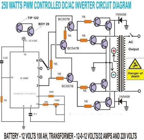
300 Watts PWM Controlled Pure Sine Wave Inverter Circuit ...
PDF Sine Wave Inverter Circuit Diagram - homes.gainesville.com Pure Sine Wave Inverter Circuit sine wave inverter circuit diagram with complete step by step program and coding, In this article I will discuss how to use push pull converter, sinusoidal pulse width modulation, h bridge and low pass LC filter to make pure sine wave inverter circuit diagram. sine wave inverter circuit digram with code The ...
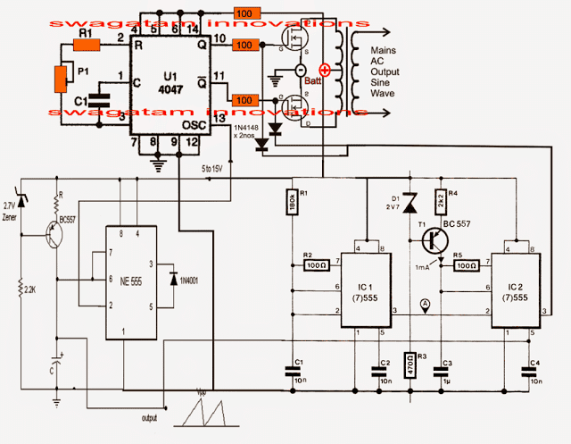
Pure Sine Wave Inverter Circuit Using IC 4047 - Homemade ...
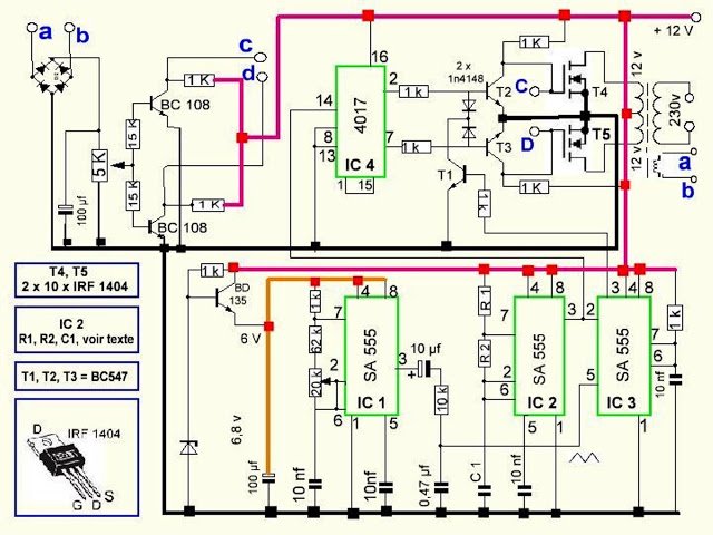
PDF Sine Wave Inverter Circuit Diagram - newspaperads.ohio.com File Type PDF Sine Wave Inverter Circuit Diagram make pure sine wave inverter circuit diagram. sine wave inverter circuit digram with code The following is a high efficiency sine wave inverter electrical diagram, the circuit with 12V battery-powered. First with a double voltage module voltage for the op amp power supply. The ICL7660 or
Power Inverters Electronics Power Supply Unit Wiring Diagram ...
PDF Sine Wave Inverter Circuit Diagram Read Online Sine Wave Inverter Circuit Diagram Sine Wave Inverter Circuit Diagram As recognized, adventure as competently as experience practically lesson, amusement, as competently as concurrence can be gotten by just checking out a books sine wave inverter circuit diagram with it is not directly done, you could take even more a propos this life, around the world.
Simple Pure Sine Wave Inverter Circuit - 500 Watt Pure Sine.pdf
Home Use off Grid Solar PV Panel Energy Power System China Home Use off Grid Solar PV Panel Energy Power System, Find details about China Solar PV System, Solar Home System from Home Use off Grid Solar PV Panel Energy Power System - Jinhua SunMaster Solar Lighting Co., Ltd.

Battery Inverter DC 12 V AC 220 V Peak 5000W Pure Sine Wave Inverter Circuit Diagram
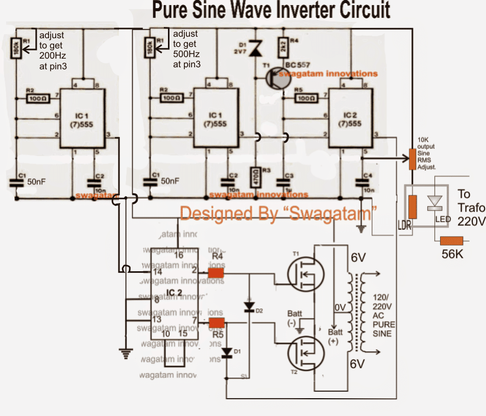
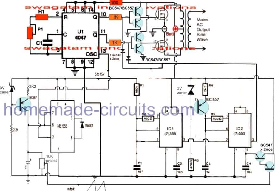
Simple Sinewave Inverter Circuits - Making Easy Circuits The following is a high efficiency sine wave inverter electrical diagram, the circuit with 12V battery-powered. First with a double voltage module voltage for the op amp power supply. The ICL7660 or MAX1044 can be selected. Op Amp 1 generates a 50 Hz sine wave as the reference signal. Op amp 2 as an inverter.

Sinewave UPS using PIC16F72 - Free Circuit Download ...
› 2012 › 11Automatic UPS / Inverter Wiring & Connection Diagram to the Home Hello sir, i have an pure sine wave 850va inverter and i m using your circuit in which one live wire is connected from inverter/ups output.. my half home appliances runs from directly grid power and half are through inverter and i use the common nutral wire.. now my question is if i switch off the input it will go in backup mode but will it ...
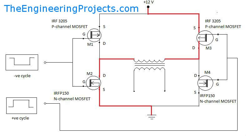
Pure Sine Wave Inverter Design With Code - The Engineering ...
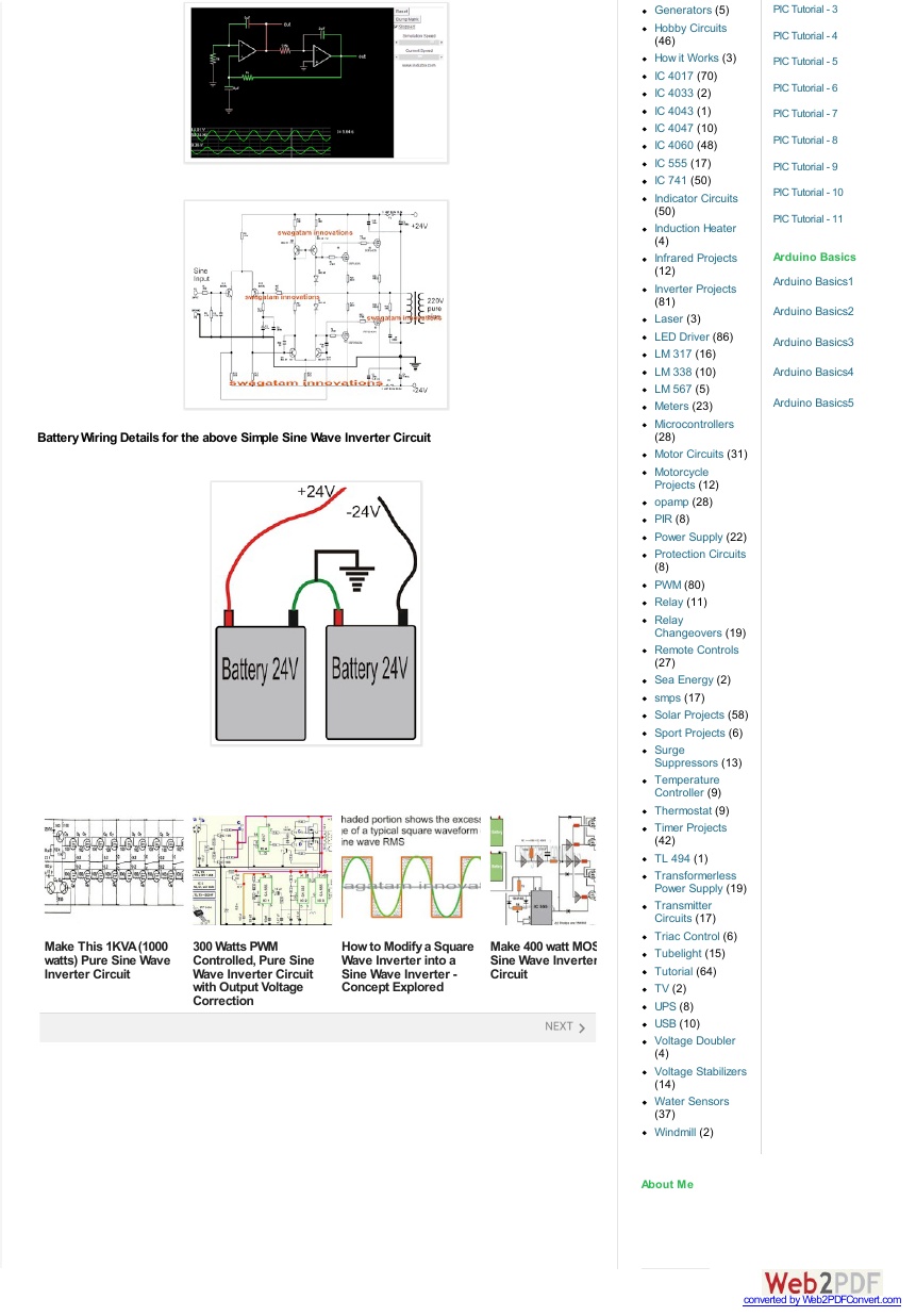
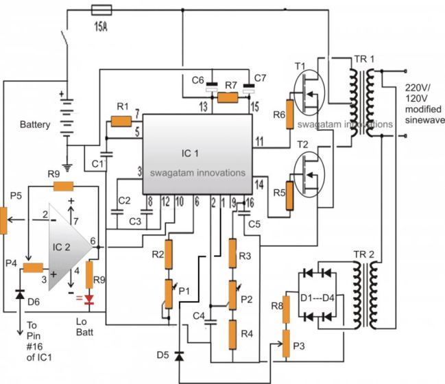
Make This 1KVA (1000 watts) Pure Sine Wave Inverter Circuit A relatively simple 1000 watt pure sine wave inverter circuit is explained here using a signal amplifier and a power transformer. As can be seen in the first diagram below, the configuration is a simple mosfet based designed for amplifying current at +/-60 volts such that the connected transformer corresponds to generate the required 1kva output.

high frequency vs low frequency pure sine wave inverter ...
Make your own Sine Wave Inverter | Full Inverter Circuit ... 13.12.2018 · The sine wave output is obtained by forming a tank circuit with the secondary winding of the inverter transformer in parallel with capacitors C5 through C7. Two 2.2µF capacitors are connected to the gates of the MOSFETs in both the banks with respect to the ground if proper sinewave is not produced. Natural frequency of the tank circuit is adjusted to …
Pure Sine Wave Inverter Circuit Using IC 4047 - Homemade ...
electricproblems.com › how-to-wire-inverter-to-rvHow to Wire an Inverter in an RV [Schematics in PDF ... 2. Modified Sine Wave Inverters. The output of this kind of inverter is NOT a pure sine wave. Its waveform has corners and edges rather than around and smooth lines. It looks more like steps: These inverters are cheaper than pure sine wave inverters and do not supply clean power to the devices.
500 watts inverter circuit -12 volt to 220 volt - Soldering Mind
Course Help Online - Have your academic paper written by a ... We offer free revision in case you are not satisfied with the order delivered to you. For such an order you are expected to send a revision request and include all the instructions that should be followed by the writer. Also remember to state the exact time the writer should take to do your revision. We offer free revision as long as the client does not change the instructions that had …

Grounding and Circuit Protection for Inverters and Battery ...
Difference between AC and DC (Current & Voltage) In such cases, the magnitude of one wave lags behind the magnitude of the other wave. This causes power loss in the circuit. In order to deliver full power to the load, the AC voltage and current needs to be synchronized (or in-phase). So the power factor fluctuates between cos 0° (power factor = 1, phase difference of 0°) and cos 90° (power factor = 0, phase difference of 90°).

Design of a single-phase SPWM inverter application with PIC ...
PDF Sine Wave Inverter Pcb Circuit Diagram current at 60 volts such that the connected transformer''pure sine wave inverter circuit diagram pcb karvea de june 24th, 2018 - read and download pure sine wave inverter circuit diagram pcb free ebooks in pdf format trailerman 7 wire diagram a level literature 2018 zimsec set book candlelight' '15 000 watt power inverter circuit diagram ...
inverter layout
PDF Pic 16f876a Pure Sine Wave Inverter Free Books Sine Wave Inverter Design - Venusdemo.comLow Cost Pure Sine Wave Solar Inverter Circuit I. 600w Pure Sine Wave Power Inverter Circuit Principle: The Inverter Is Divided Into Four Parts, Each Part Make A PCB Board. They Are "power Board", "SPWM Driver Board", "DC-DC Driver Board" And "protection Board". 1. Power Board

Circuit diagram of power circuit of the inverter | Download ...
pure sine wave inverter circuit diagram - Microcontrollers Lab Pure sine wave inverter circuit of SPWM the Diagram below shows the circuit diagram of sinusoidal pulse width modulation with two output both are on alternatively after every 10 ms. spwm circuit diagram Output of SPWM circuit diagram SPWM circuit output Gating signals for H bridge

700W 12V Pure Sine Wave Inverter
DIY Cheap 1000W Pure Sine Wave Inverter (12V to 110V/220V ... Decent high power commercial pure sine wave inverters are very expensive! They range from $120-$400. With the EGS002 you can design all sorts of inverters with input voltage, output voltage and power ratings of your choice! For as low as $20, depending on your specs and where you source your components. What's On The EGS002 Board?

How to a make Sine Wave Inverter with 555 Timer in Proteus ...
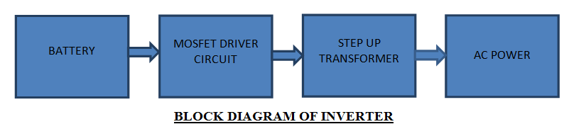
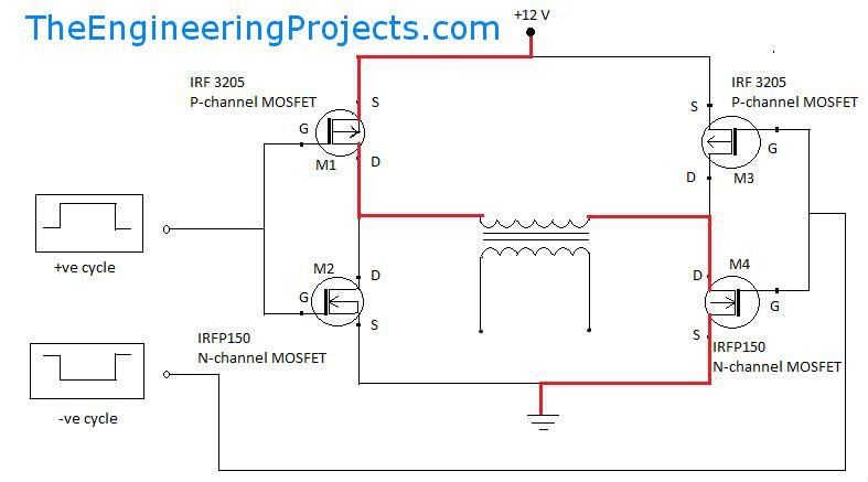
Pure Sine Wave Inverter Design With Code - The Engineering ... Pure Sine-Wave Inverter. Pure Sine wave inverter consist of a microcontroller unit which generates a switching signal of 15 KHz, an H-bridge circuit to convert the signal into AC, a low pass LC filter circuit to block the high frequency components and the transformer unit to step-up the voltages. Block diagram of sine wave circuit is given below:

DIY 1000W Pure Sinewave 12v-220v Inverter (EGS002 16 MOSFET ...
Pic12f683 inverter circuit with project file download This issue is fix by adding a delay timer circuit which is preset to 5 seconds and the 5 sec delay circuit output is connected to the (VCC) pin1&pin8 of the mosfet driver and this fix the issue delay circuit below watch the video below to see me testing the circit download the mod project file for pic12f683 here

Digital Inverter Circuit Diagram, Microtek Digital Inverter ...
PDF Low Cost Pure Sine Wave Solar Inverter Circuit A pure sine wave is highly desirable because the vast majority of electrical plug-in appliances are designed to run on a true sine wave signal. This is accomplished through an inverter circuit using electronic components. Two types of inverters currently exist on the market; a modified sine-wave inverter and a pure sine wave inverter.
Simple 100W Inverter Circuit Diagram and Its Working
PDF PWM Techniques: A Pure Sine Wave Inverter Pure sine wave inverters will power devices with more accuracy, less power loss, and less heat generation. Pure sine wave inversion is accomplished by taking a DC voltage source and switching it across a load using an H-bridge.
Inverter Circuit Diagram for Android - APK Download
Report: DC/AC Pure Sine Wave Inverter - Schematic Design Report: DC/AC Pure Sine Wave Inverter. Here the project report of DC/AC pure sine wave inverter. This report focuses on DC to AC electrical power inverters, which aim to efficiently transform a DC power source to a high voltage AC supply, just like electrical power that would be presented at an electrical wall outlet.
DC/AC Pure Sine Wave Inverter
(PDF) Physics English Part 2 new | Ankit Sharma - Academia.edu Download Free PDF. Download Free PDF. Physics English Part 2 new. 448 Pages. Physics English Part 2 new. Ankit Sharma. Download Download PDF. Full PDF Package Download Full PDF Package. This Paper. A short summary of this paper. 8 Full PDFs related to this paper. Read Paper. Download Download PDF. Download Full PDF Package ...

Simple Pure Sine Wave Inverter Circuit - 500 Watt Pure Sine.pdf
PDF Sine Wave Inverter Circuit Diagram - health.savannahnow.com Get Free Sine Wave Inverter Circuit Diagram harmful virus inside their computer. sine wave inverter circuit diagram is approachable in our digital library an online entry to it is set as public in view of that you can download it instantly. Our digital library saves in merged countries, allowing you to get the most less latency period to ...
Simple Sinewave Inverter Circuits
PDF Sine Wave Inverter Circuit Diagram - video.gadsdentimes.com Online Library Sine Wave Inverter Circuit Diagram Sine Wave Inverter Circuit Diagram Yeah, reviewing a ebook sine wave inverter circuit diagram could increase your close connections listings. This is just one of the solutions for you to be successful. As understood, capability does not suggest that you have wonderful points.
Pure Sine Wave Inverter 1000w-1500x1125px - Power Inverter ...
Study of Modified Sine Wave Inverter

sine wave inverter circuit digram with code

DOC) DC/AC PURE SINE WAVE INVERTER WITH MINIMAL HARMONIC ...
6000w Dc-ac Pure Sine Wave Power Inverter Circuit Diagram ...

DC-to-AC Power Inverter Solutions | Microchip Technology

Catherine (Itaporanga, 17, Brazil)'s comments from Memoar ...

Design of a single-phase SPWM inverter application with PIC ...
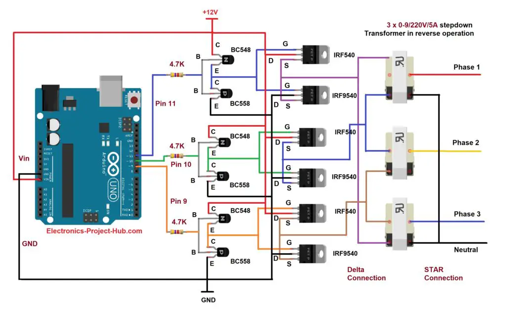
Three Phase Inverter Circuit Diagram – DIY Electronics Projects
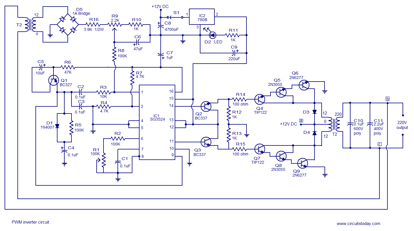
PWM inverter circuit based on SG3524 : 12V input, 220V output ...
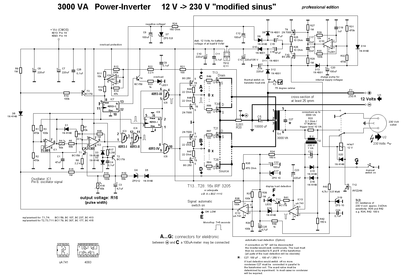
3000W Power Inverter 12V to 230V - Inverter Circuit and Products

ACEsolutions: PURE SINE WAVE INVERTER WITH LED AND LCD
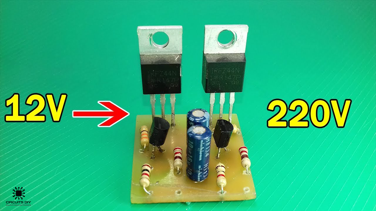
Simple 12V To 220V Inverter Circuit Using IRFZ44 MOSFET

1KVA (1000 watts) Pure Sine Wave Inverter Circuit ...
Pure Sine Wave Inverter Design With Code - The Engineering ...


Comments
Post a Comment