40 air brake chamber diagram
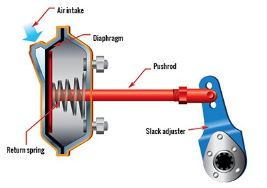
Long Stroke Brake Chambers Watch your brake chambers! Most new vehicles are now being equipped with long-stroke brake chambers.This allows more stroke than older models. You will find clamp type 20 and clamp type 16 long stroke chambers on the steering axles and clamp type 24 and clamp type 30 long stroke chambers on other axles. Front Brake Air Chamber. At the right is a typical front brake air chamber installed on the front axle. Below, is a diagram of a front brake air chamber, courtesy of GMC Truck Division. It has a single diaphragm which pushes the push rod to the right when air enters into the chamber from the air inlet. All of these brake chambers have sizing ...
Meritor M820625 SimpleCheck Air Brake Stroke Indicator Tool, 5/8" Pushrods, 1-3/4" OD Part# 650-M820625 Multi-Piece Discount $1.39 USD Meritor M820750 SimpleCheck Air Brake Stroke Indicator Tool, 3/4" Pushrods, 1-3/4" OD Part# 650-M820750 $1.24 USD Bendix K034202 Brake Chamber Dust Cap Part# 060-K034202 $3.17 USD Brake Chamber Tech Info
Air brake chamber diagram
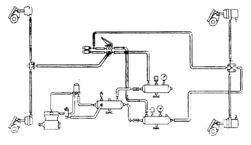
Front Brake Air Chamber. At the right is a typical front brake air chamber installed on the front axle. Below, is a diagram of a front brake air chamber, courtesy of GMC Truck Division. It has a single diaphragm which pushes the push rod to the right when air enters into the chamber from the air inlet. All of these brake chambers have sizing ... Below is a simplified air schematic that shows the drive axle brake chambers and related parts. Shown in this schematic are the lines and components that are involved with just the drive axle brakes. The front and tag axle brakes are not included for simplicity's sake. Piping Diagram Page 6 Wiring Diagrams Page 6 Warning lamp and Page 8 ... Spring Brake Chamber) 7 Drain valve 8 Load Sensing valve - pneumatic 9 Test point 10 MCER Valve. ... 9 8 9 10 9 14 9 13 11 11 11 11 11 11 PIPING DIAGRAM - 2 Line Air Brake system, 3 Axle Semi-Trailer, Spring Brakes, Air Suspension. Fig 5 6 WIRING DIAGRAM - ISO 3731 (24S ...
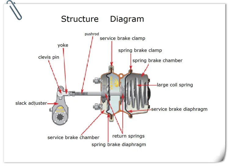
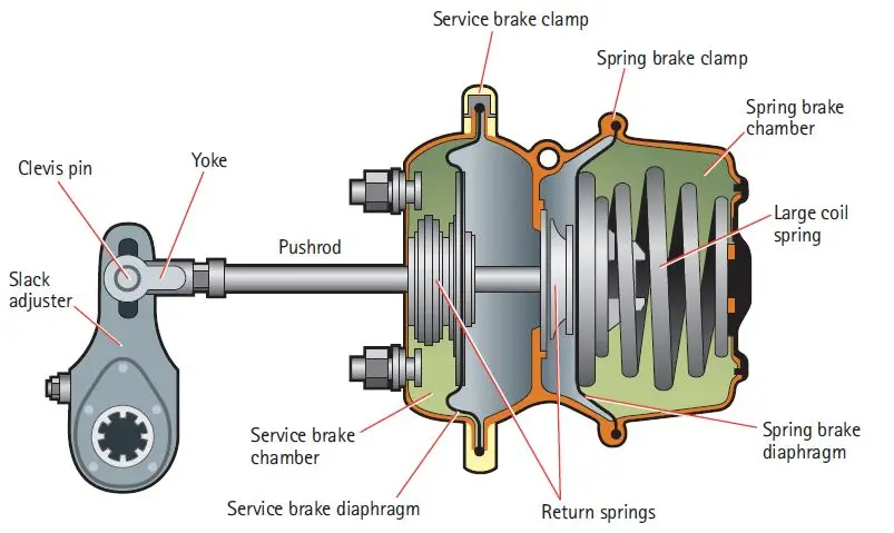
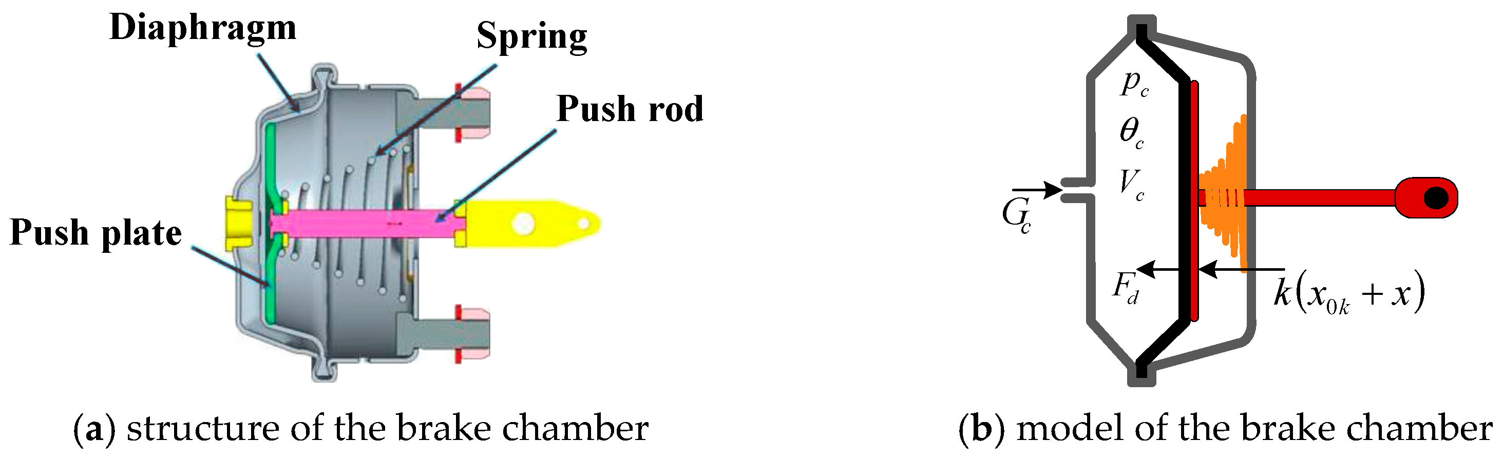
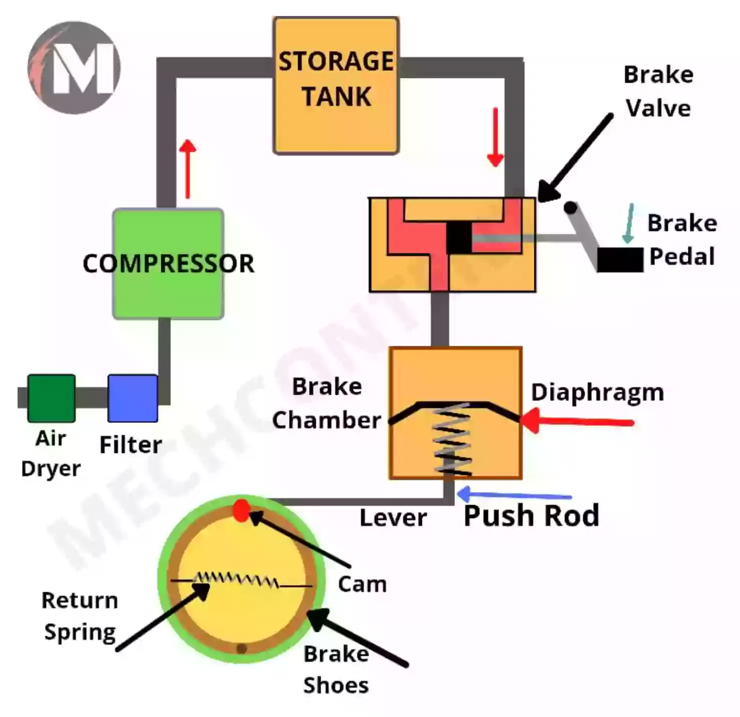
Air brake chamber diagram. Section 15 - Brake Chambers and Components FPA No. Description Application Alternate No. Brake Chamber Wedge Brakes Type 12 CA2503 Brake Chamber Wedge Brakes 1212B-3.00 AN1212B-3.00R ... AIR BRAKE HOSES Diaphragm VH90 Vacuum Brake VH90-4 Hydropowers 885820R1 T Release Bolt Assy T16 - 30/30 Brake 11M011 Chambers FP1003015 Clevis Pin ITAL 33557V diy repairing service break diaphragm (pancake) on type 3030 brake chamber without killing yourself. simple easy cheap repair. on a big semi truck. how to re... Typical 6 Wheel Air Brake System. These diagrams are provided for basic identification only. Always consult a professional technician to properly troubleshoot your system. Typical 10 Wheel Brake System. These diagrams are provided for basic identification only. Always consult a professional technician to properly troubleshoot your system. (v) Brake chamber. Brake chamber is used to transfer the force of compressed air to mechanical linkages. Service-brake chambers convert compressed air pressure energy into mechanical force and movement, which apply the vehicle’s brakes. A brake chamber is a circular container divided in the middle by a flexible diaphragm.
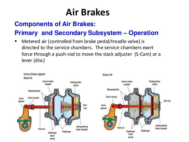
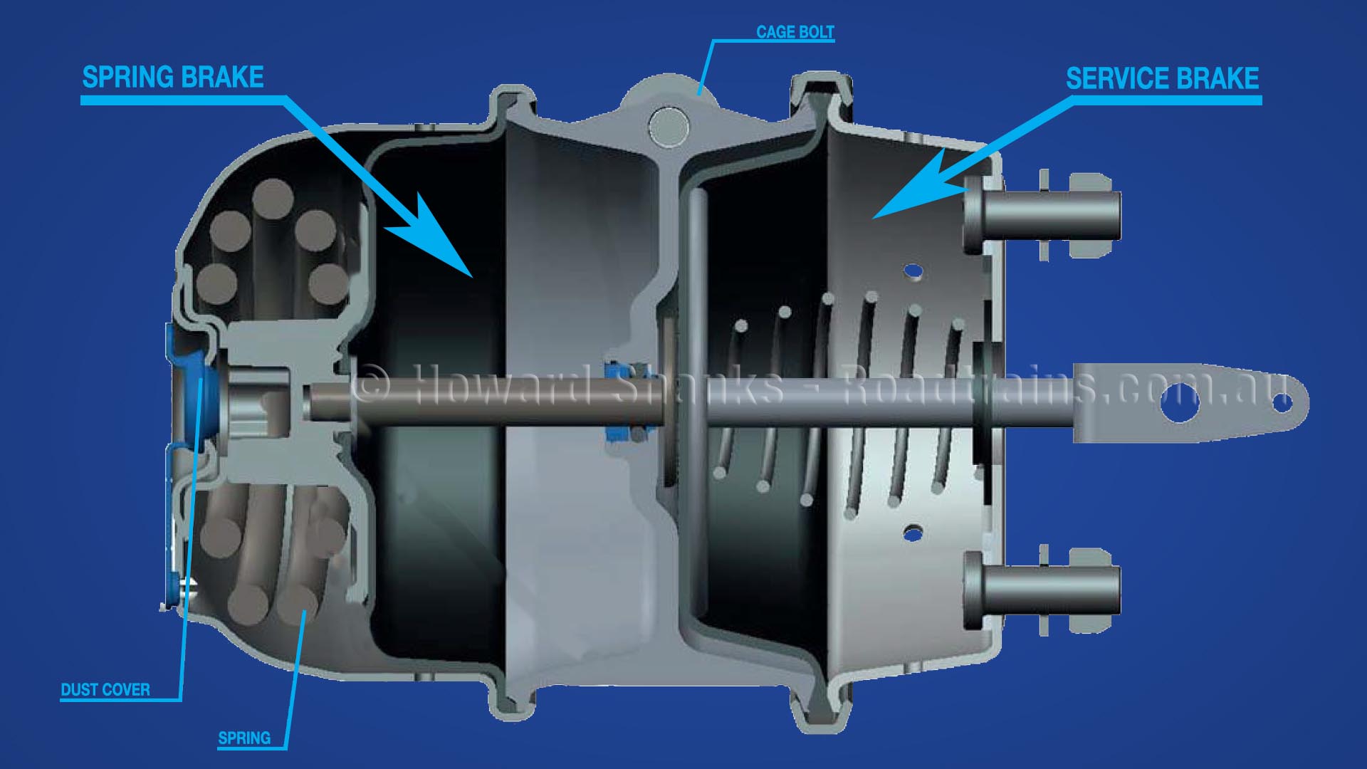
·Used to apply and release service brakes on tractor or trailer ·Crack Pressure 4.6 PSI TWO AND FOUR PORT WITH ANTI-COMPOUNDING ·Built-in anti-compounding two-way check valve for spring brake Control ·Crack Pressure 4.6 PSI TWO PORT WITH INTEGRAL BRACKET ·Used to apply and release service brakes on tractor or trailer The diagram shows the brakes in the applied position. The S-cam is rotated so the high points have acted against the cam rollers and forced the brake shoes against the drum. When the brakes are released, the brake cam shaft returns the brake cam to the normal position. brake chambers and applies force to the push rod, transferring the force to the SCam or air disc brake. (See page 19 for more about foundation brakes.) Frictional forces slow the wheels and the vehicle comes to a stop. When the brakes are released, the air in the brake chambers is able to be quickly rel eased and enable the vehicle to drive away. The service brakes will operate with apply and release air in the service (control) line by the tractor hand control or foot control valve. HOW TO IDENTIFY YOUR SYSTEM All types of trailer air brake systems can be identified for troubleshooting purposes by starting from the brake chamber or spring brake assembly.
hydraulically or with air. Air brakes are similar in some ways to hydraulic brakes except that compressed air is used to actuate the brakes instead of brake fluid. The potential energy of an air brake system is from compressed air. The force delivered to the wheels has nothing to do with the pressure applied to the brake pedal. This video gives a detailed overview of the various components of service chambers and spring brakes. We identify long stroke, standard stoke, and different ... The purpose of an air brake system on heavy duty vehicles is to convert air pressure to mechanical energy to activate the foundation brakes. Federal Motor Vehicle Safety Standard 121 dictates how this is to be done for over-the-road vehicles. The purpose of this book is to help you construct Meritor WABCO Truck and Tractor air systems. 121, Air Brake Systems. Any change or addition to the system may cause the vehicle to no longer be in compliance with these MVSS. MVSS 121 requirements cover (but are not limited to) the following: •Air compressor build-up time •Air reservoir volume •Service brake stopping distance •Brake actuation time •Brake release time
ONTAP - Air Brakes
Standard Clamp Type Brake Chamber Type Adjustment Limit Type Adjustment Limit 9 1-3/8" 24 1-3/4" 12 1-3/8" 30 2" 16 1-3/4" 36 2-1/4" 20 1-3/4" DD-3 2-1/4” NOTE: Long stroke chambers are identified with square air ports or port bosses and special trapezoid ID tags. Long Stroke Type Brake Chamber Type Adjustment Limit Type Adjustment Limit
IICL Chassis Technical Bulletin – CTB 022, June 3, 2015 Title ...
-Brake drum out of round.-Brake chamber diaphragm failure.-Wrong brake lining.-Broken slack adjuster or foundation brake parts. 8.) Air Pressure Will Not Rise To Normal-Faulty air gauge (registering incorrectly).-Excessive valve or fitting leakage.-Governor out of adjustment.-Slipping compressor drive belt.-Faulty compressor.-Broken supply line ...

Air Brake System - Parts, Working, Diagram, Principle, Advantages
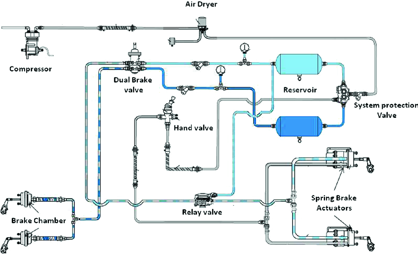
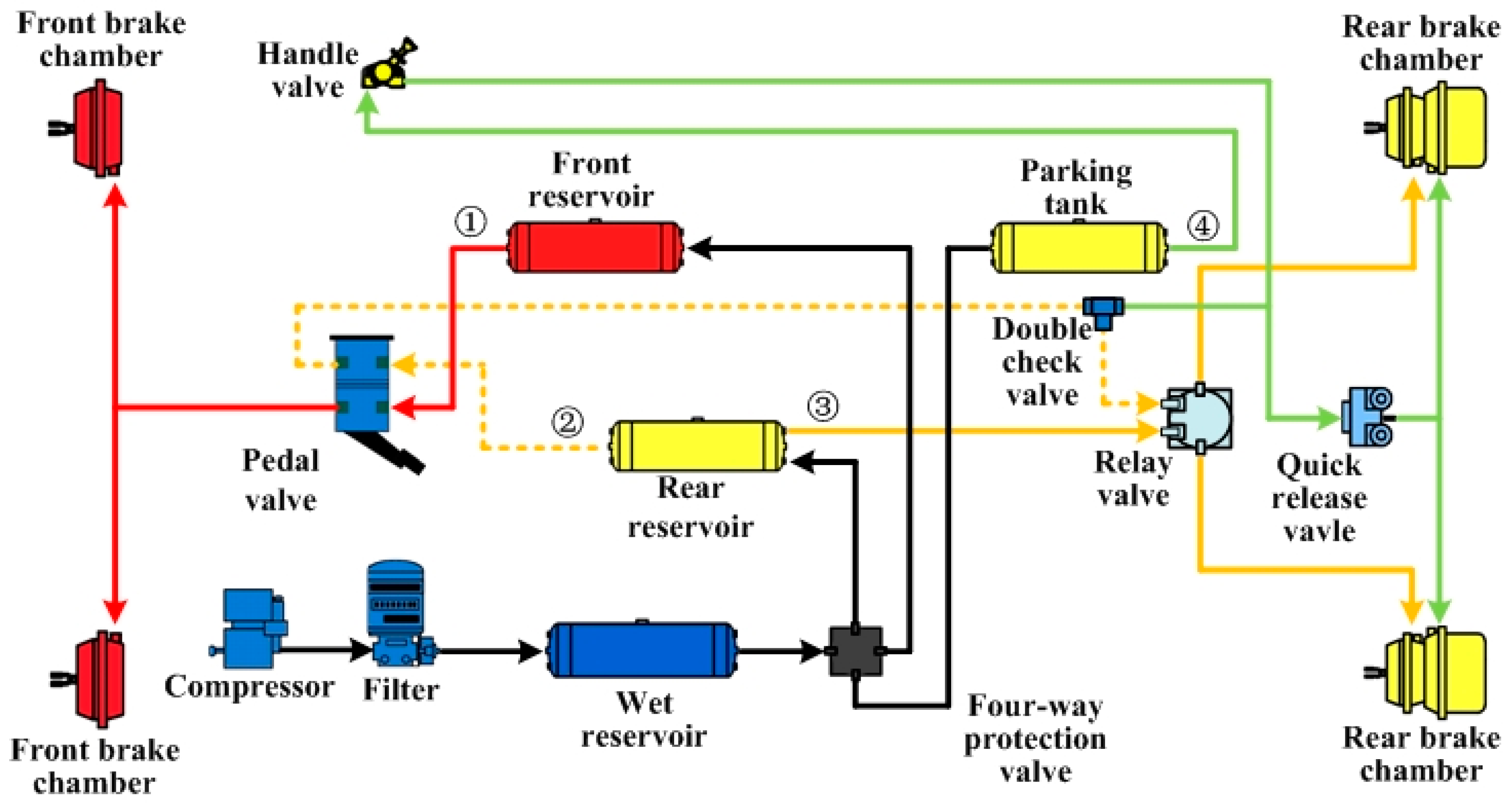
Download scientific diagram | A general layout of a truck air brake system. ... 1) and the quick release valve and finally to the brake chambers mounted on ...
Manual: Bendix Air Brake Systems - Parts, Functions, Diagrams ...
An air brake or, more formally, a compressed air brake system, is a type of frictionbrake for vehicles in which compressed air pressing on a piston is used to apply the pressure to the brake pad needed to stop the vehicle. We are supplying kinds of Air Brake Chamber Types with different size. Types: Single Room Air Brake Chamber & Double Room ...

A model of the relay valve used in an air brake system ...
Piping Diagram Page 6 Wiring Diagrams Page 6 Warning lamp and Page 8 ... Spring Brake Chamber) 7 Drain valve 8 Load Sensing valve - pneumatic 9 Test point 10 MCER Valve. ... 9 8 9 10 9 14 9 13 11 11 11 11 11 11 PIPING DIAGRAM - 2 Line Air Brake system, 3 Axle Semi-Trailer, Spring Brakes, Air Suspension. Fig 5 6 WIRING DIAGRAM - ISO 3731 (24S ...
Hot Sale T24/30dd Brake System Auto Part Air Brake Chamber ...
Below is a simplified air schematic that shows the drive axle brake chambers and related parts. Shown in this schematic are the lines and components that are involved with just the drive axle brakes. The front and tag axle brakes are not included for simplicity's sake.

Effect of Brake Chamber Pressure Area on Dynamic and Static ...
Front Brake Air Chamber. At the right is a typical front brake air chamber installed on the front axle. Below, is a diagram of a front brake air chamber, courtesy of GMC Truck Division. It has a single diaphragm which pushes the push rod to the right when air enters into the chamber from the air inlet. All of these brake chambers have sizing ...

Changing double structure brake chamber T30/30 on semi ...

What Is Air Brake Systems? | Working of Air Brake Systems ...

Basic system components - SGI
Truck Air Spring Rear Brake Chamber 3030 T30/30 - Buy 3030 Brake Chamber,T30/30 Brake Chamber,Spring Brake Chamber Product on Alibaba.com
A MATHEMATICAL MODEL FOR AIR BRAKE SYSTEMS IN THE PRESENCE OF ...
Applied Sciences | Free Full-Text | A New Method for ...

Pneumatic Braking System In Automobile | Air Braking System ...

Air Brake System - Parts, Working, Diagram, Principle, Advantages
Air Brake Service Brake Systems

China Customized Brake Chamber Type 2424 Manufacturers ...
Service Brake Subsystem | Ontario.ca
Hot Sale T24/30dd Brake System Auto Part Air Brake Chamber ...

64 Air brake ideas | air brake, brake, air

Air Brake System Working Diagram - Mechanical Booster

Relay valve - SGI
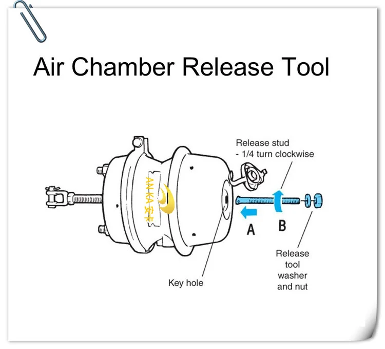
How to Manually Release Truck Brakes – Australian Roadtrains

Technology

http://www.truckt.com Air Brake Chambers Explained
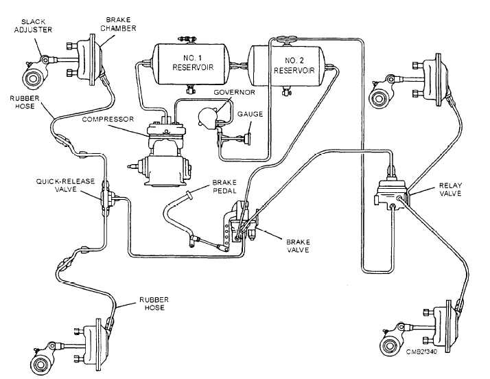
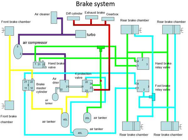
Figure 7-39.Typical air brake system

Hankuk Air Brake

http://www.truckt.com Air Brakes Anti-Compounding Theory
Electronics | Free Full-Text | Pneumatic ABS Modeling and ...

China HOWO Brake Chamber Manufacturers and Suppliers - OEM ...

A general layout of a truck air brake system. | Download ...
Virtual Simulation with Statistical Approach on Performance ...
Pneumatic braking system: Definition, Principle, Diagram ...
Applied Sciences | Free Full-Text | A New Method for ...

Bus Air Brake System Diagram | Air brake, Brake system, System
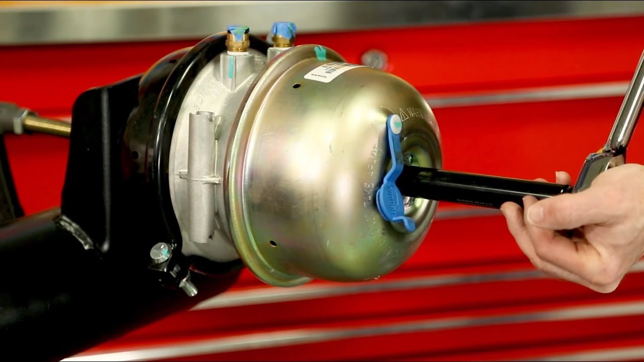
Heavy Duty - Caging Brake Chambers

Air Brake Chamber for America Market (T30) - China Brake Part ...

Chapter 31 Air Brake Servicing. - ppt video online download

Air brake (road vehicle) - Wikipedia
The air flow in truck brake system


Comments
Post a Comment