41 push to exit button wiring diagram
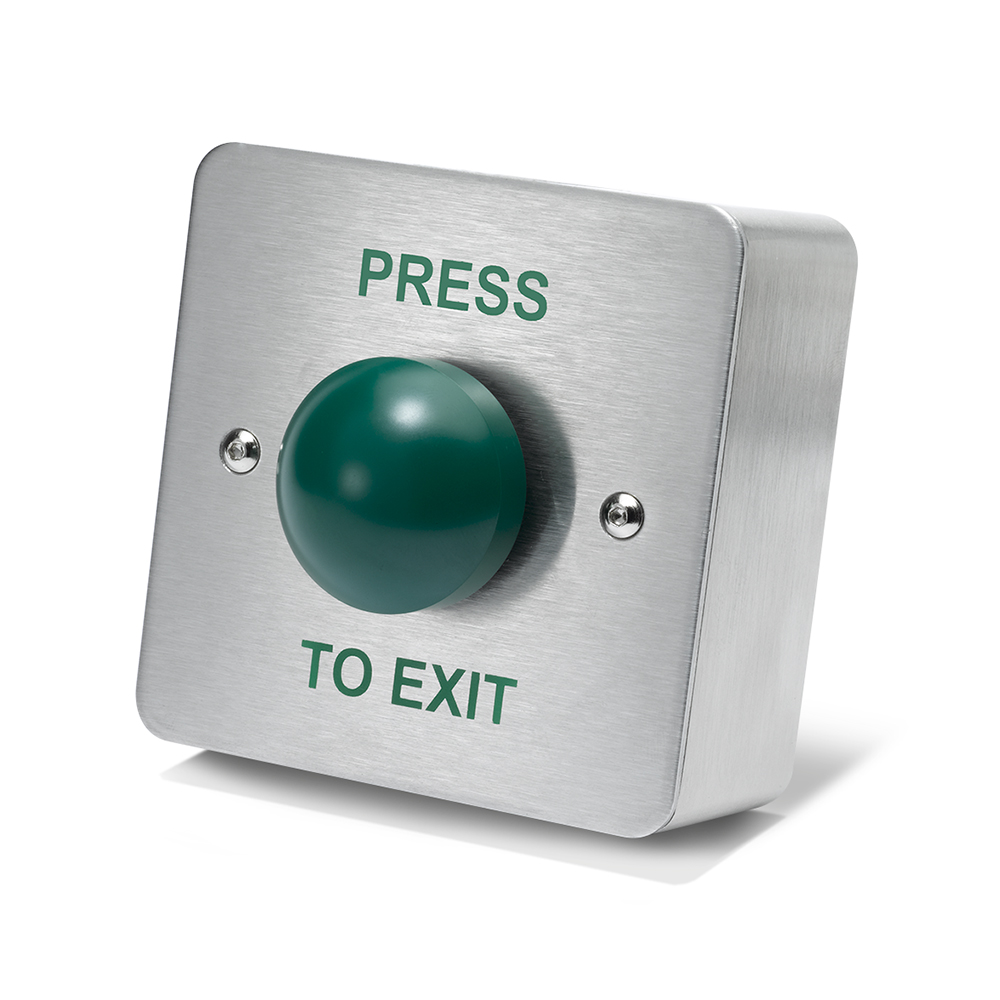
TS-2 Request to Exit Station The TS-2 request to exit station, with square push button, provides a convenient way to add authorized access control to a variety of applications. Features PUSH TO EXIT or REX Button In the event of an emergency, a PUSH TO EXIT or REX button must be included (per code requirements) when connecting a REX device to a maglock. A push-to-exit button does exactly what its name implies: It allows you to exit when you push it if your door doesn't open with the REX or traditional handles.
The push to exit button is connected to the access control application, which controls the locking mechanism of the door, using wires. Any individual that needs to exit the building or pass through the door simply has to push or press the button. When pushed, it momentarily releases the fail-secure or fail-safe lock of the door.

Push to exit button wiring diagram
LED Illuminated Exit Switch, w/ timer. CM-30 Series UL compliant LED illuminated 'request to exit' (REX) switches conform to NFPA code requirements and are ADA compliant. They are designed to control electric locks, electromagnetic locks, electric strikes and low energy door operators. They may also be used for shunting, bypassing alarms ... Wiring Diagram Electromagnetic Door Lock, EM Lock, Push Button, Power Supply 12v, Carane ngonek kunci magnet. SAMPLE WIRING DIAGRAMS. SECURITY DOOR CONTROLS ... HANDS FREE & ADA COMPLIANT LATCH RETRACTION EXIT DEVICE APPLICATION 13 ... Push Button (Exterior) PUSH TO OPEN PUSH TO OPEN Push Button (Interior) (COM) (N/O) (COM) (N/O) GRN (Closed Loop) Remove factory installed jumper 13
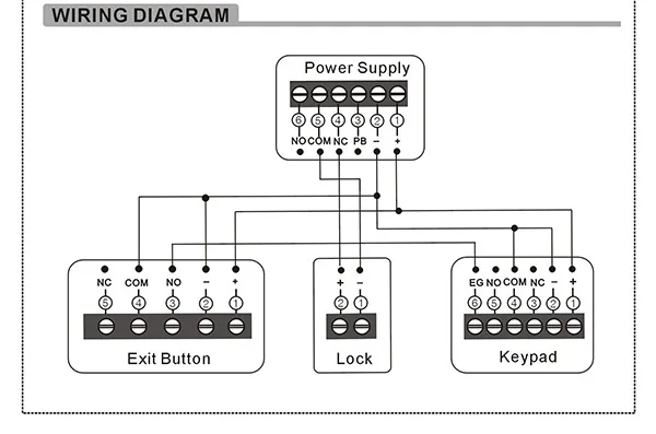
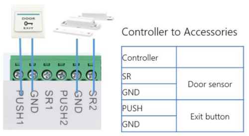
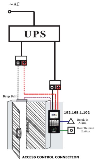
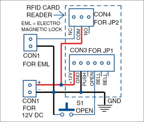
Push to exit button wiring diagram. A crucial step in setting up your push-to-exit button is properly wiring all the components. In an IP system like Kisi, this will involve the door lock, the access reader, the controller, the power supply, and the push-to-exit button (as well as optional contact sensors). A push button (pushbutton) is a simple human interface for controlling some aspect of a machine or process. The push button requires a force to push the button to change the electrical operation from off to on or vice versa. The condition of the output is usually momentarily. Some common everyday pushbuttons we use are keyboards keys. The TS-2T request to exit station with electronic timer and square push button, provides a convenient way to keep the door unlocked for a specified amount of time, allowing for easy entry or egress. The door will relock when the relay time has expired. Features. Standard Features. Switch mounted on single gang wall plate with 430 stainless ... 2, The wiring diagram from a push exit button to access controller. we suggest to use 2 cores cable, the diameter is above 0.3mm². 3, The wiring cable from the electric door lock to access controller. We suggest to use 2 cores electronic cable, sectional area is above 1.0 mm².
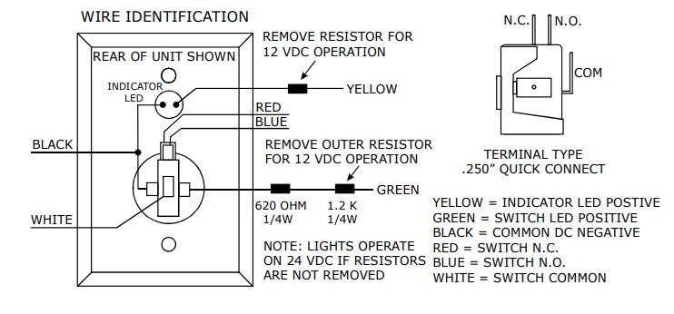
The following common wiring diagrams are available: One Single Door with Panic Bar. Electric Latch Retraction, with Auto Operator ... Remote push button with Electric Latch Retraction - Fire Rated Application; ... riser diagrams falcon exit devices - WIRING INSTRUCTIONS— fail secure strike with one button Power Supply Push Button N/O Fail Secure Strike Polarity Insensitive Depressing the push button would close the circui t, allow power to flow and release the strike. Power Supply may be AC or DC, depending on the requirements of the strike. How to wire an Exit Button or Sensor Description. This wiring diagram is to describe where to wire door exit button/ Sensor to Dahua Access controller. Prerequisites. 1. Door Exit button/ sensor 2. DHI-ASC1204B Wiring Diagram identification of the wires and a typical wiring diagram showing a power supply, motion detector, push button and Magnalock so as to comply with the BOCA code for access controlled egress doors. There is a point to note about the internal design of the unit. Both the push button contacts and
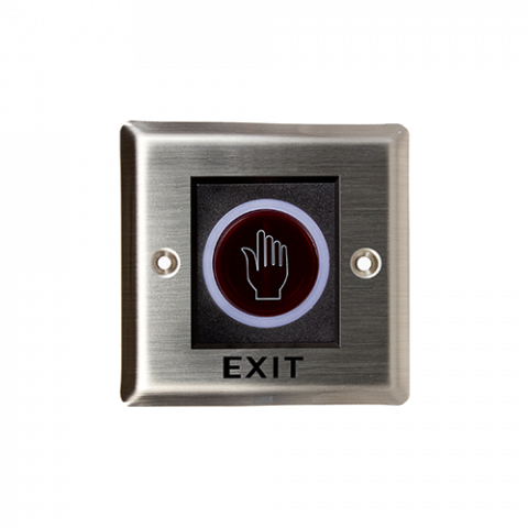
Piezoelectric push buttons for indoor or outdoor use (IP65). LED ring around button changes from green to red or red to green when the button is pressed. Timed or toggle output. Includes separate manual override button in case power to piezoelectric push button fails. Relay rated 2A@30VDC with two individually programmable outputs (NO/NC). The following common wiring diagrams are available: Standalone with access control and Magnetic Lock · Wireless Multi-Technology Reader - GCK Magnetic Lock Installation & Support. Mag-Lock w/ Push Buttons. Wiring Diagram for Mag-Lock w/ Push Buttons Wiring Diagram - Biometric & Push Button. If this is not available you may use an AC power ... Push to Exit Button Wiring Diagram (1) Push-button dry contact rating: 10A/125VAC For safe operations, do not exceed the ratings above. (2) For normally open requirements, connect wires to N.O dry contact of PUSH-BUTTON (3) For normally closed requirements, connect wire to N.C dry contact of PUSH-BUTTON How to Replace the Plastic Sheet Rotary ... THIS WIRE DIAGRAM, BE SURE ALL PRODUCTS ARE VOLTAGE COMPATIBLE. (3) ALL WIRING MUST CONFORM TO NATIONAL, STATE AND LOCAL CODES. ... Pressing the code compliant "Push to Exit" push button will bypass the keypad and motion sensor, unlocking the magnetic lock for a fixed 30 seconds.
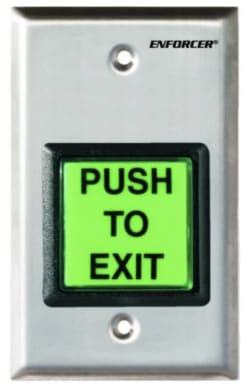
Alarm Controls TS-2, Push to Exit Button, GREEN
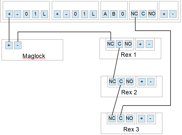
Wiring Multiple REX Devices in Series. The basic hook-up for a single REX (Request to Exit) device consists of the REX, a power supply, and a Maglock. When the REX sees motion, power is removed from the maglock. The power supply voltage must be between 12 and 24 VDC. In this same configuration scenario, multiple REX devices may be connected in ...
DRB004S-PTE – ICS Security Solutions
Suitable for applications both indoors and outdoors, STI has a variety of emergency buttons, round push switches, fire alarm buttons, 3-in-1 push button, call point switches, and multipurpose push button switches. Many are UL, cUL and ADA.

Exit Push Button - an overview | ScienceDirect Topics
Common Wiring diagrams. wiring diagram for QEL panics mag lock wiring diagrams. chexit wiring diagram. lever locks for fire doors. emergency release tool. two single doors with panic bars. two single doors with panic bars. push button release electric strike. - WIRING INSTRUCTIONS— magnetic lock or fail safe strike with button, keypad and PIR ...

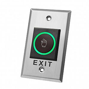
China No Touch Infrared Door Release Exit Button for Access ...
• Large, 1-9/16" (39.7mm) diameter button with red cap •20-gauge stainless steel faceplate For emergency release applications to Push the button once to engage; key 990 Oversized Tamper-Resistant Handicap & Exit Mushroom Buttons • Ideal for request-to-exit applications accommodating ADA requirements • Available in Spanish and French ...
TLEB101 | ZKTeco Europe
Paxton exit button - E50. Part No: 356-310. Quick ref: 0217770. Login or register to see prices. In Stock.

Why Aren't You Installing Access Control? A Guide to Getting ...
CM-9700/9710: 2" Piezoelectric Push/Exit Switch. Camden Heavy-Duty CM-9700 series is a one piece all aluminum construction with a non-moving Piezo actuator. CM-9800 Series illuminated switches are 'light touch' capacitive switches that are both water and vandal resistant. The cast metal construction, easy operation and high visibility of these ...

VIS-7001 Indoor + Outdoor Weather, Waterproof Rated IP65 ...
Typical Wiring Diagrams For Push Button Control Stations 3 Genera/ Information @ Each circuit is illustrated with a control circuit (continued) schematic or line diagram and a control station wiring diagram. l The schematic or line diagram includes all the components of the control circuit and indicates their

Dortronics Piezoelectric Exit Switch
LocksOnline Wiring Diagram 004. Oct 30, · Request to Exit Wiring Diagram ds ds installation guide high performance request to 3 3 8 disabling the request to exit the ds can be disabled by using terminal r and an external device such as an access control or burglar alarm system. Push Buttons.
Gatekeeper Instructions v4 h4.2
Rectangular Emergency Exit Electric Door Strike for Push to Exit - VIS-EL106 Electromagnetic Lock for Sliding Door VS-MOR.300 & VS.MOR.600 - Installation Video Push to Exit Buttons: VIS-7006, VIS-7012, VIS-7027, VIS-7026 - Installation Video
Infrared Exit Button No Touch access control Door exit Push ...
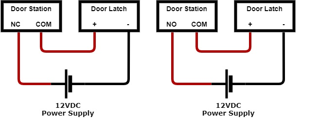
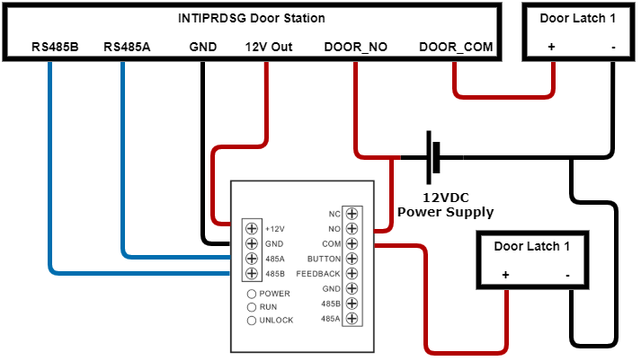
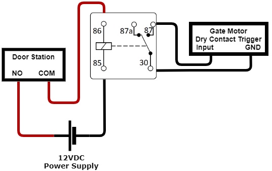
In the diagram below the INTIPRDSG Door Station is being used and is utilising the 12V output. This can be substituted for a 12VDC Power supply. Push-To-Exit Button. If you require a push to exit button, ensure it is a NO button. Wiring the latch as per one of the three diagrams, then connect your button.
Intercom Door Latch / Gate / Exit Button Wiring - Cornick
The 906 and 908 are mushroom push buttons switches for operating automatic doors. The RCI 906 push button is dedicated for handicap use and the RCI 908 push button is utilized for exit operation. These push buttons quickly and easily mount to single gang surface or recessed electrical boxes.

EM lock working with push button only
SAMPLE WIRING DIAGRAMS. SECURITY DOOR CONTROLS ... HANDS FREE & ADA COMPLIANT LATCH RETRACTION EXIT DEVICE APPLICATION 13 ... Push Button (Exterior) PUSH TO OPEN PUSH TO OPEN Push Button (Interior) (COM) (N/O) (COM) (N/O) GRN (Closed Loop) Remove factory installed jumper 13

TS-2 - ASSA ABLOY
Wiring Diagram Electromagnetic Door Lock, EM Lock, Push Button, Power Supply 12v, Carane ngonek kunci magnet.
AmetaWiki - How to wire an Exit Button or Sensor?
LED Illuminated Exit Switch, w/ timer. CM-30 Series UL compliant LED illuminated 'request to exit' (REX) switches conform to NFPA code requirements and are ADA compliant. They are designed to control electric locks, electromagnetic locks, electric strikes and low energy door operators. They may also be used for shunting, bypassing alarms ...

Touch Plastic Exit Button HMT-PK2B - Shenzhen Huiyuxin ...
Intercom Door Latch / Gate / Exit Button Wiring - Cornick

Securitron EEB2-EEB3N Emergency Exit Buttons | Taylor ...

Security door controls, Typical wiring, Electrical ...

Exit Push Button - Sbj Maglock Door Push To Exit Switch ...

PI Manufacture
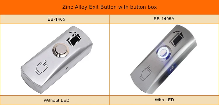
Push To Exit Buttons Mounting Wiring Diagram Eb-1405 - Buy ...
Wiring Multiple REX Devices in Series – ProdataKey, Inc.
Exit Push Button | Push Button Switch - JakinID
Y:\WIRING DIAGRAMS\ED900-WD\WEBSITE DIAGRAMS\900-WD043 Model (1)

Infrared Sensor No Touch Exit Switch (K-K2)-Access Control ...

Wiring diagram of exit button of access control switch
Gatekeeper Instructions v4 h4.2

Low Volt Wiring – Unit 4 – School of Lock and Electronic Security

Door Access Control System Exit Button Door Push Release Switch With Indicator Light
Basic Installation Of Access Control System | Full ...
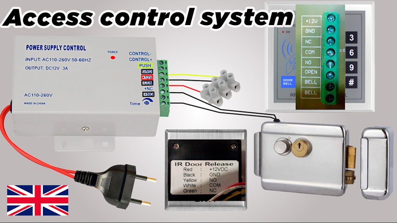
Access control system with door lock, card reader and security exit button ðŸ˜ï¸
Securitron PB2 Push To Exit Button
Intercom Door Latch / Gate / Exit Button Wiring - Cornick

UHPPOTE Momentary Push to Exit Button Switch NO/COM Output Stainless Steel Panel for Access Control Hollow Door

Buy Hygienic Hands-Free Door Release / Exit Button ...

Metal Infrared Induction No Touch Door Release Button Exit ...
Exit button China Manufacturer | Ework

Push to Exit Buttons - Videx Security

VIS-7005 - Indoor Ultra Thin Push + Touch To Exit Button For ...

Three-Wire Circuit with Multiple Push Buttons – Basic Motor ...
How to Install a Push-to-Exit Button


Comments
Post a Comment