42 Image Intensifier Diagram
Image intensifier | Radiology Reference Article ... Image intensifiers (II) are utilized to convert low energy x-radiation into visible light images. Frequently the detector portion of an x-ray C-arm used in operating theaters, the image intensifier has a low scatter input portion made of low absorption substances such as titanium or aluminum 1,2.Image intensifiers are several thousand times more sensitive compared to standard 400-speed screen ... Radiologic equipment unit 7 challenge questions ... - Quizlet Diagram the image intensifier tube, label its principal parts, and discuss the function of each. See Figure 25-4 page 407 Trace the path of information-carrying elements in a fluoroscopic system from incident X-rays to video image.
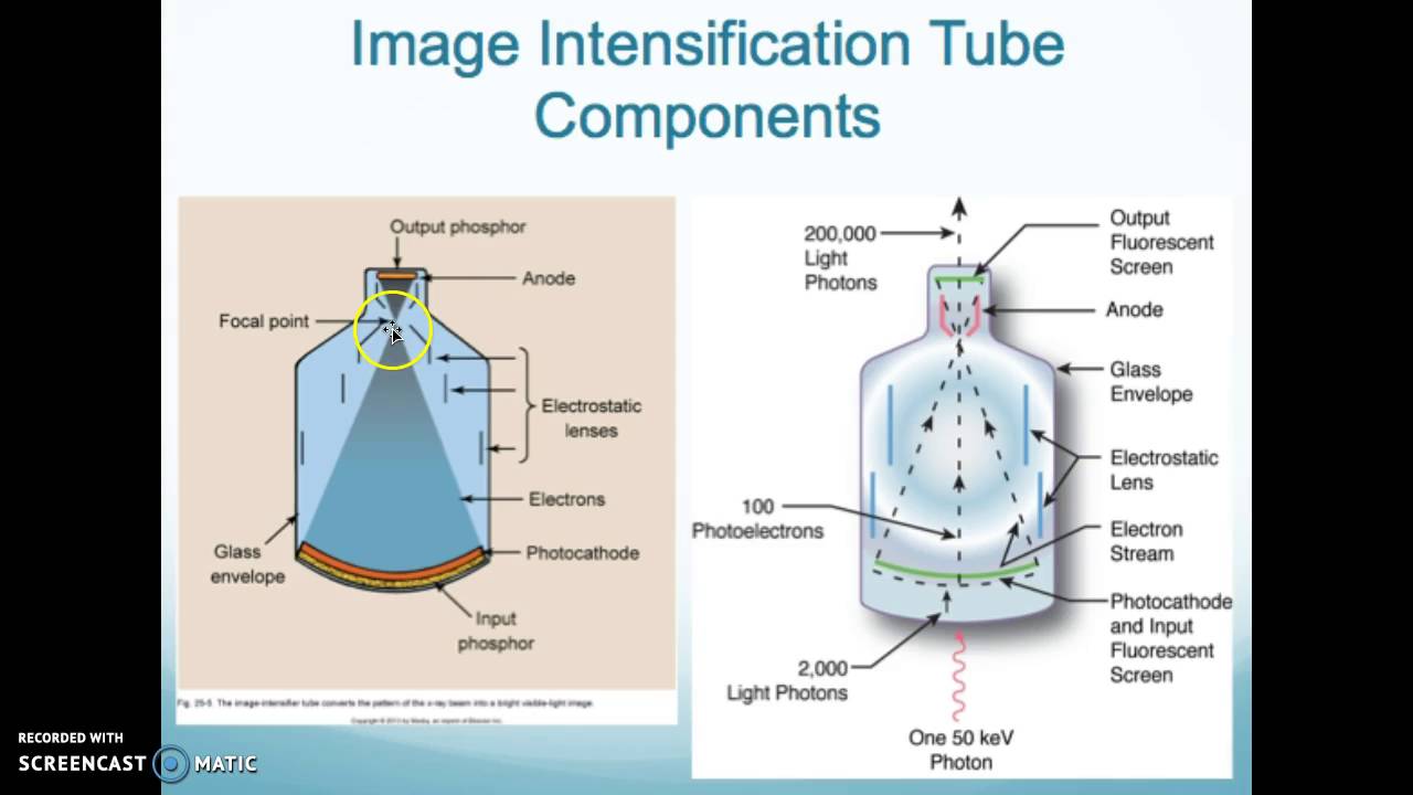
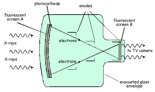
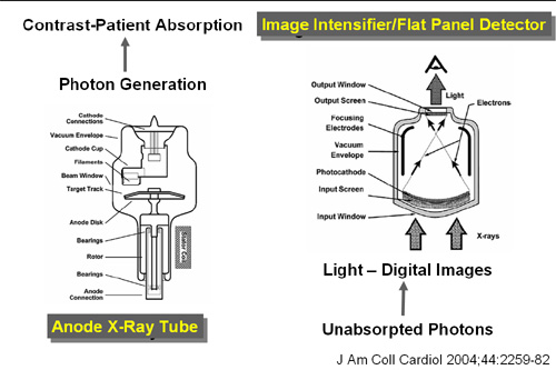
The AAPM/RSNA Physics Tutorial for Residents | RadioGraphics The x-ray image intensifier converts the transmitted x rays into a brightened, visible light image. Within an image intensifier, the input phosphor converts the x-ray photons to light photons, which are then converted to photoelectrons within the photocathode. The electrons are accelerated and focused by a series of electrodes striking the output phosphor, which converts the accelerated ...
Image intensifier diagram
Introduction to Fluoroscopic ... - Musculoskeletal Key Figure/Photograph/Diagram of Movement Description Nomenclature Used in This Atlas ; Cephalad or caudad tilt (also known as decline) Fig. 3.3A and B : The C-arm rotates around a transverse axis with the image intensifier (ImInt) rotating superiorly while the X-ray source rotates inferiorly (or vice versa). Image intensifier - Wikipedia An image intensifier or image intensifier tube is a vacuum tube device for increasing the intensity of available light in an optical system to allow use under low-light conditions, such as at night, to facilitate visual imaging of low-light processes, such as fluorescence of materials in X-rays or gamma rays (X-ray image intensifier), or for conversion of non-visible light sources, such as ... Image Intensifier - an overview | ScienceDirect Topics Hence, an image intensifier affords an entire two-dimensional picture and gives rise to the potential for performing Raman microscopy. In the Raman microscope, the laser beam is focused into a sample and the focal point is transferred by a microscope and a monochromator to the active surface of an image intensifier.
Image intensifier diagram. Image Intensifier Diagram | Quizlet Start studying Image Intensifier. Learn vocabulary, terms, and more with flashcards, games, and other study tools. Image Intensified Fluoroscopy - Radiology Key In the 1950s the image intensifier was introduced into the fluoroscopic system. The image intensifier improved the process in two ways. First, it brightened the image significantly, eliminating the need to dark-adapt and improving the details that could be seen. Second, it allowed for a means of indirectly viewing the fluoroscopic image, first by mirror optics and later by television monitors ... PDF IMAGE INTENSIFIER APPLICATION NOTE - Photek Ltd figure 5), an image intensifier with a 100 MΩ MCP can operate with an output current of 7x10⁻⁷ A, equivalent to 2x10¹⁰ photons/s incident on the image intensifier at a QE of 20%. This calculation assumes a uniform distribution of photons over the face of the image intensifier. For high gain image intensifiers using multiple Diagram of an image intensifier. | Download Scientific Diagram Download scientific diagram | Diagram of an image intensifier. from publication: Infrared Devices And Techniques (Revision) | The main objective of this paper is to produce an applications ...
Parts & Accessories - asu-nvg.com Spare Parts & Accessories for ASU Night Vision Goggles. The helmet mounting solution for night vision goggles has come a long way in the last 20 years, and to date, Aviation Specialties Unlimited, Inc. is proud to distribute the most effective and precise products of helmet mounting, parts, and accessories. X-Ray Image Intensifiers: Design and Future Possibilities X-ray image intensifiers: design and future possibilities BY P. SCHAGEN Philips Research Laboratories, Redhill, Surrey RH1 5HA, U.K. [Plate 1] The most significant parameters of X-ray image intensifiers are considered in relation to their main components, the X-ray detection screen, the photocathode, the electron optics and the output screen. Schematic of gated optical image intensifier (GOI) used ... Download scientific diagram | Schematic of gated optical image intensifier (GOI) used for timegated FLIM. from publication: Characterisation of new gated optical image intensifiers for ... Fluoroscopy - Radiology Key A diagram of an II is shown in Figure 9-3. There are four principal components in an image intensifier: (1) an input screen that absorbs incident x-rays and converts the image to an electron pattern, (2) the electron optics, which accelerates the electrons and minifies the electron image,
PDF Introduction to Image Intensifier Tubes The terminology "image intensifier" and "image converter" are frequently confused. In par-ticular, image conversion refers to the transfer from an invisible to a visible spectral range, such as image converters used in night vision. On the other hand, image intensifiers which perform as the name suggests often also function as image converters. PDF Generation III based P45 White Phosphor Image Intensifiers Schematic diagram of an image intensifier. The goggle optics focuses light on the photocathode. The photocathode is a precisely fabricated thin layer of semiconductor material that absorbs light in a wide band from the near infrared through the visible to the ultraviolet. Image Intensifier Tubes - tandfonline.com IMAGE INTENSIFIER TUBES 497 OR K Diagram 1. Diagrammatic cross-section of the image intensifier tube. luminance, which for the human eye is much more favourable for the evaluation of the image. For the measurement of the resulting improve- ment, investigations were carried out with a bakelite phantom, as de- scribed by BURGER (1). PDF OEC 9900 Elite - Equipped MD • 12/9/6" (31/23/15 cm) tri-mode image intensifier: A larger field of view than our standard 9/6/4.5" (23/15/10 cm) image intensifier, for many vascular applications or wherever a larger field of view is required. Cardiac Surgery and Mobile Cardiac Cath lab/EP lab 9900 Cardiac 30 F/S (25 F/S @ 50 Hz)
Technology Introduction X-ray Image Intensifiers|Canon ...
PDF Night Vision Technologies Handbook NVDs include Image Intensifier (I 2) devices, thermal imaging cameras, integrated night vision systems (INVSs), and near infrared (NIR) illuminator technology. An example of an I 2 display is shown in . Figure 1-1. NVDs can enhance almost any emergency

An Overview of the Waterjet Intensifier - MultiCam Canada
The Image Intensifier (II) | Radiology | SUNY Upstate ... The Image Intensifier (II) The image intensifier is comprised of a large cylindrical, tapered tube with several internal structures in which an incident x-ray distribution is converted into a corresponding light image of non-limiting brightness. A picture of an image intensifier television (II-TV) system is shown below.
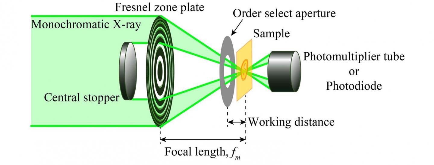
Scanning Transmission X-Ray Microscope for Lithium Battery
The operation of fluoroscopy diagram - Professional ... The X-ray penetrates the human body and is modulated by the density of different parts of the body to form an invisible X-ray image on the input screen of the intensifier. Newheek fluoroscopy diagram can satisfy your different purchase demand.
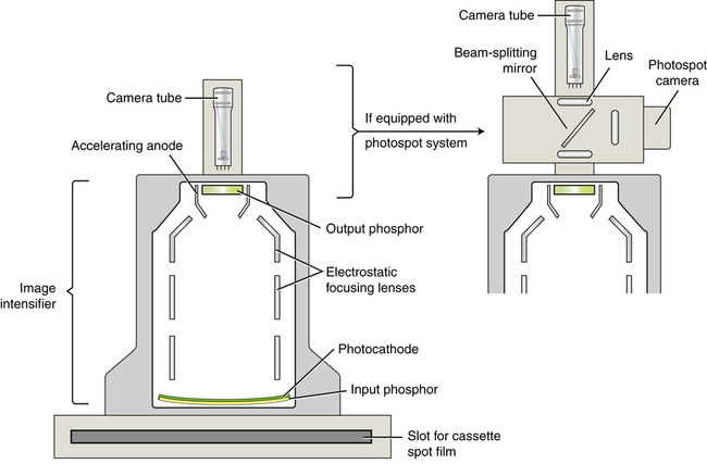
Image Intensified Fluoroscopy | Radiology Key
Flouroscopic imging - SlideShare IMAGE INTENSIFIER DESIGN Image intensifier was discovered in 1950s-to produce an image bright enough to allow cone vision without giving the pt an excess radiation exposure. The components of an x-ray image intensifier The tube itself is an evacuated glass envelope ,a vacuum tube containing- 1.input phosphor and photocathode .

Figure, X-ray image intensifier. Contributed by Hassan Ahmad ...
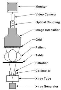
Modern Fluoroscopy Imaging Systems - Image Wisely A schematic of an image-intensified fluoroscopy system is shown in Figure 1. The key components include an X-ray tube, spectral shaping filters, a field restriction device (aka collimator), an anti-scatter grid, an image receptor, an image processing computer and a display device.

Icon Machine Tool | TECHNI Waterjet Electric Servo ...
PDF Main Schematic Blocks of Image Intensifier Power Supply ... The image intensifiers have a large range of applications now a day. They are commonly used in the night vision devices. There are two main technologies used for night vision, the one is the infrared technology, and the other image intensifier. In fact from several years there are devices which use both technologies, creating an image based on a

Image Intensifier Diagram | Quizlet
PDF Nvg Components and Goggle Operation - Gensale.net image intensifier if the light level is high enough. Image Disparity - This condition may exist when there is a difference in brightness between the two image-intensifier assemblies within the same binocular. Output Brightness Variation - This condition is evidenced by areas of varying brightness in or across the image area. The lower contrasts ...

The Image Intensifier Tube
Hold 3500 Volts Up To Your Eye - Hackaday Most image intensifiers work in the near IR spectrum, which does pass through glass. You are thinking about far IR which does not. ... Basic diagram of the tube in this article.

Image intensifier - Wikipedia
PDF TECHNICAL MANUAL - Night Vision Home Image Intensifier Inspection Criteria, page 2-3 Unit Troubleshooting, page 2-3 Unit Maintenance Procedures, page 2-3 Direct Support Servicing, page 3-2 Direct Support Troubleshooting, page 3-3 Direct Support Maintenance Procedures, page 3-17 ARMY TM 11-5855-262-23&P-2 AIR FORCE TO 12S10-2PVS7-12 MARINE CORPS TM 09500A-23&P/2A NAVSEA SW215-AT ...

Image Intensifier - an overview | ScienceDirect Topics
PDF Image Intensifier User Guide - photek.com Image Intensifiers Introduction Image Intensifiers consist of three basic elements: • An input window capable of transmitting light over a particular spectral range that can span from the near UV to near IR with photocathode deposited on its inner surface. • One or more microchannel plates (MCPs) to provide electron gain.

ACCF/AHA/HRS/SCAI Clinical Competence Statement on Physician ...
PPTX PowerPoint-presentatie Image intensifiers come in different sizes, but always have a round shape. This is an easy way to distinguish the resulting images from rectangular Flat Detector images (next). Collimator setting needs to be adapted to the size and position of the image detector: no X-ray radiation should be sent out to where it is not detected.

Fluoro #1 Review Video Diagram | Quizlet
Image Intensifier - an overview | ScienceDirect Topics Hence, an image intensifier affords an entire two-dimensional picture and gives rise to the potential for performing Raman microscopy. In the Raman microscope, the laser beam is focused into a sample and the focal point is transferred by a microscope and a monochromator to the active surface of an image intensifier.
The Detectivity of Intensifier Image Tubes
Image intensifier - Wikipedia An image intensifier or image intensifier tube is a vacuum tube device for increasing the intensity of available light in an optical system to allow use under low-light conditions, such as at night, to facilitate visual imaging of low-light processes, such as fluorescence of materials in X-rays or gamma rays (X-ray image intensifier), or for conversion of non-visible light sources, such as ...

Characterisation of new gated optical image intensifiers for ...
Introduction to Fluoroscopic ... - Musculoskeletal Key Figure/Photograph/Diagram of Movement Description Nomenclature Used in This Atlas ; Cephalad or caudad tilt (also known as decline) Fig. 3.3A and B : The C-arm rotates around a transverse axis with the image intensifier (ImInt) rotating superiorly while the X-ray source rotates inferiorly (or vice versa).
RADT 086 Image Intensification Tube

Hydraulic Pressure Intensifiers - How do They Work? - Bright ...
ICC - Meteor - Cosmos
A Cyberphysics Page

Figure 7.11, Detailed principle of an image intensifier ...
![PDF] An image intensifier-scintillator device for ...](https://d3i71xaburhd42.cloudfront.net/806dd4bdb98c62ab88fad85de0d8d2a1803b31fd/2-Figure1-1.png)
PDF] An image intensifier-scintillator device for ...

Ch 4.1 – The image intensifier – Brian's Radiology Learning Diary
File:Image intensifier.jpg - wikidoc

SHOCK-RESISTANT IMAGE INTENSIFIER - diagram, schematic, and ...

Diagram of an image intensifier. | Download Scientific Diagram

Image intensifier tube | Medical radiography, Diagnostic ...

intensifier diagram : avwaterjet

Night Vision 101: Seeing in the Dark | B&H Explora

Fluoroscopy Equipment Operation - ppt video online download

Image intensifier-based digital radiography system ...

An Image Intensifier Tube High Resolution Stock Photography ...
Modern Fluoroscopy Imaging Systems | Image Wisely

X-ray image intensifier - Wikiwand

HOUSING MOUNTED IMAGE INTENSIFIER TUBE - diagram, schematic ...

Image Intensifier Tube Diagram | Quizlet
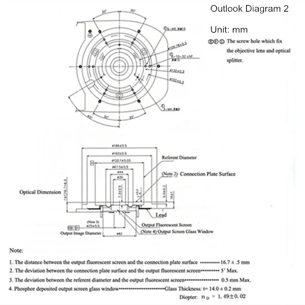
Image Intensifier X-ray Machine Prices/x Ray Generator - Buy ...
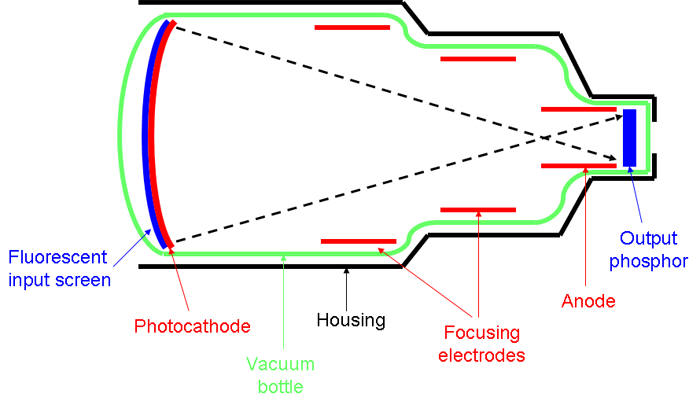
Image Intensifier (Converter) Tube (early 1960s) | Museum of ...

Image Intensifier Tubes - how it works.

Test and analysis of spectral response for UV image intensifier
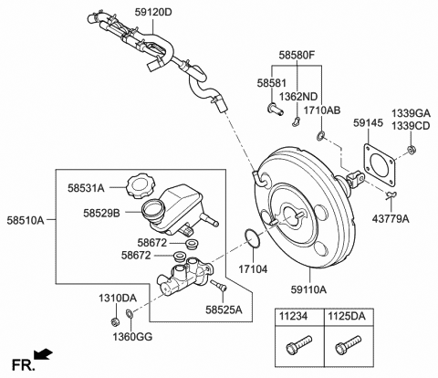
59120-3V300 Genuine Hyundai Hose Assembly-Intensifier

Rad Tech CE, ASRT, ARRT® CE, Category A Credits | Radiology ...

JaypeeDigital | eBook Reader

The principle behind image intensifier


Comments
Post a Comment