42 iron nickel phase diagram
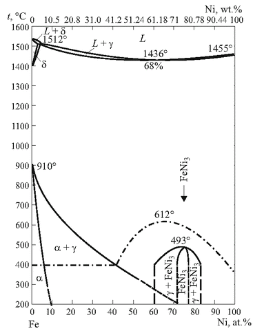
Fe-ni phase diagram Alpha and gamma solubility limits in iron-nickel phase diagram at high temperatures - quench- and-anneal and diffusion couple techniques and electron probe microanalysis. Document ID. 19650020214. Document Type. Technical Memorandum (TM) Authors. Goldstein, J. I. (NASA Goddard Space Flight Center Greenbelt, MD, United States) Figure 2.6: The iron-nickel phase diagram, which includes terminology describing meteorites of specific Ni concentrations. i.e. a medium octahedrite is an iron meteorite which contains 6.5 - 10.5 Ni wt %. Also, this figure shows the nickel percentages often found associated with
Iron--Nickel--Tungsten Phase Diagram. Showing 1-4 of 25 pages in this report. PDF Version Also Available for Download. Physical Description. 21 p. Creation Information. Winslow, F. R. January 1, 1971. Context ...

Iron nickel phase diagram
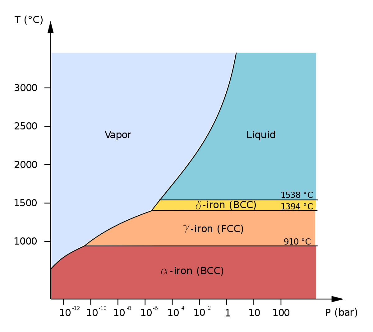
Phase Diagram Resources from ASM International. Alloy phase diagrams and crystal structure data are used by metallurgists, materials engineers, and materials scientists to develop new alloys for specific applications; fabricate these alloys into useful configurations; design and control heat treatment procedures for alloys that will produce the required mechanical, physical, and chemical ... Iron-nickel (Fe-Ni) alloy is the most abundant component in the Earth's core [1]. The amount ofNi in the core is about 5.5wt%, on the basis of geochemical models [2]. The phase diagram and physical properties of Fe have been extensively studied [3]. Iron crystallizes in the bcc structure under ambient conditions, and it Iron-Carbon Phase Diagram • Pure iron experiences two changes in crystal structure before it melts.--At room temperature the stable form, ferrite with BCC crystal structure.--Ferrite experiences a polymorphic transformation to FCC austenite at 912°C. • At 1394°C, FCC austenite reverts back to BCC! ferrite phase, which finally melts at ...
Iron nickel phase diagram. The Cu-Ni phase diagram [ 2007Tur] depicts a continuous fcc solid solution between Cu and Ni. The solid solution breaks into Cu-rich and Ni-rich fcc phases at low temperatures. The Fe-Ni phase diagram [ 1991Swa] is characterized by a very narrow solidification range, with a peritectic reaction between (δFe) and liquid yielding (γFe). Schematic phase diagrams of iron-nickel system at the pressure of the inner core boundary. (a) If the Ni content in the outer core is less than that of the fcc-hcp-liquid triple point, the inner core could be composed of the hcp phase. (b) If the nickel content in the Fe-Ni-Si (Iron-Nickel-Silicon) Section II: Phase Diagram Evaluations JPEDAV (2010) 31:184–185 DOI: 10.1007/s11669-010-9653-4 1547-7037 ÓASM International Fe-Ni-Si (Iron-Nickel-Silicon) V. Raghavan The review of this system by [1988Ray] presented a an ordered phase FeNi3 (L12, AuCu3-type cubic) forms tentative liquidus projection, partial isothermal sections at congruently from c. The geometry of the temperature-composition phase diagram of iron-nickel alloys suggests that the hcp-fcc-liquid triple point is located at 10 to 20 wt.% Ni at the pressure of the inner core boundary. The fcc phase could crystallize depending on the nickel and silicon contents in the Earth's core, both of which are fcc stabilizer. Previous article
Iron--Nickel--Tungsten Phase Diagram. F. Winslow Published 1971 Materials Science In support of a study of the properties of liquid-phase-sintered iron-nickel-tungsten alloys, the most probable phase diagram was drawn. The space diagram is shown as a series of isothermal sections between 1,650 and 800° C and a liquidus and solidus projection. Cr-Fe-Ni (Chromium-Iron-Nickel) Cr-Fe-Ni (Chromium-Iron-Nickel) Raghavan, V. 2008-12-05 00:00:00 JPEDAV (2009) 30:94-95 Section II: Phase Diagram Evaluations DOI: 10.1007/s11669-008-9449-y 1547-7037 ASM International V. Raghavan The detailed review of the early results of the phase (a¢) phases. The Cr-Ni phase diagram [Massalski2] has a equilibria of this system by [1988Ray] presented ... We will limit our discussion of phase diagrams of multi-component systems to binary alloys and will assume pressure to be constant at one atmosphere. Phase diagrams for materials with more than two components are complex and difficult to represent. An example of a phase diagram for a ternary alloy is shown for a fixed T and P below. osti.gov journal article: phase-diagram study of alloys in the iron-chromium-molybdenum-nickel system
A. Phase Diagrams 1. Iron-Copper System The iron-copper phase diagram, taken from Hansen,3 is presented in Figure 1. Hansen3 also gives a thorough review of the work done on the system up to 1957. A review of more recent work, up to 1963 was done by . Elliott~ The most recent version of the phase diagram testing and metallographic evaluation. A time-temperature-hardness diagram was prepared for each iron, nickel, and cobalt combination. Scanning electron microscopy was performed to document microstructural features while phase identification was performed using X-ray diffraction and energy Addendum. In Vol. 12, No. 3, page 301 ("The Fe-Ni (Iron-Nickel) System," by L.J. Swartzendruber, V.R Itkin, and C.B. Alcock), in Table 6 three. figures contained incorrectly placed decimal points ... Phase Diagrams • Indicate phases as function of T, Co, and P. • For this course:-binary systems: just 2 components.-independent variables: T and Co (P = 1 atm is almost always used). • Phase Diagram for Cu-Ni system Adapted from Fig. 9.3(a), Callister 7e. (Fig. 9.3(a) is adapted from Phase Diagrams of Binary Nickel Alloys , P. Nash
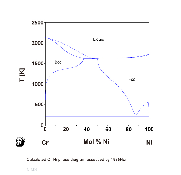
Cr-Ni (NIMS)
Fe-Ni Phase Diagram u. T-r I. Guidstein and R. E. Ogilvie ABSTRACT The CY and y solubility limits in the Fe-Ni phase diagram have been redetermined at temperatures above 500OC. couple and a quench-and-annea technique were used. limits were measured with an electron probe microanalyzer. Both a diff'usion The solubility
Catalysts | Free Full-Text | Ni Promotion by Fe: What ...
by LJ Swartzendruber · 1991 · Cited by 329 — Phase Diagram Evaluations. The Fe-Ni (Iron-Nickel) System. By L.J. Swartzendruber. National Institute of Standards and Technology. V.P. Itkin.

Figure 3 from Elastic Properties of Metals and Alloys, I ...
Jun 01, 1991 · These changes are also applicable to this table as printed in “Fe-Ni (Iron-Nickel)” in Phase Diagrams of Binary NickelAlloys, P. Nash, Ed., ASM International (1991). The correct table is printed in this evaluation in Phase Diagrams of Binary lron Alloys, H. Okamoto, Ed., ASM International, to be published (1993).
![Fe-Ni phase diagram. [16] | Download Scientific Diagram](https://www.researchgate.net/profile/Rcs-Navarro/publication/286807012/figure/fig3/AS:587504373760005@1517083366669/Fe-Ni-phase-diagram-16.png)
Fe-Ni phase diagram. [16] | Download Scientific Diagram
PHASE DIAGRAM. KEY POINTS OF Fe-C Diagram Phases: ... • Gray iron was the original "cast iron", and is an iron alloy ... • The principal alloying element is 15 to 25% nickel.[1] • Secondary alloying elements are added to produce intermetallic precipitates, which include cobalt,

Quantitative elaboration of the defect structure of iron ...
Phase-diagram study of alloys in the iron-chromium-molybdenum-nickel system Item Preview remove-circle Share or Embed This Item. Share to Twitter. Share to Facebook. Share to Reddit. ... Phase-diagram study of alloys in the iron-chromium-molybdenum-nickel system by Bechtoldt, C.J.; Vacher, H.C. Publication date 1957 Publisher National Bureau of ...
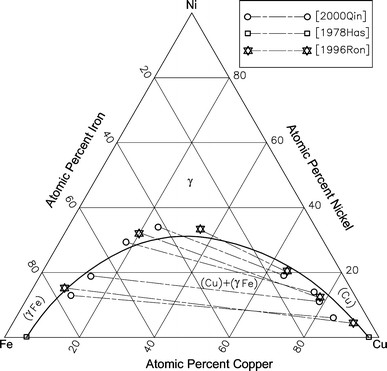
Cu-Fe-Ni (Copper-Iron-Nickel) | SpringerLink
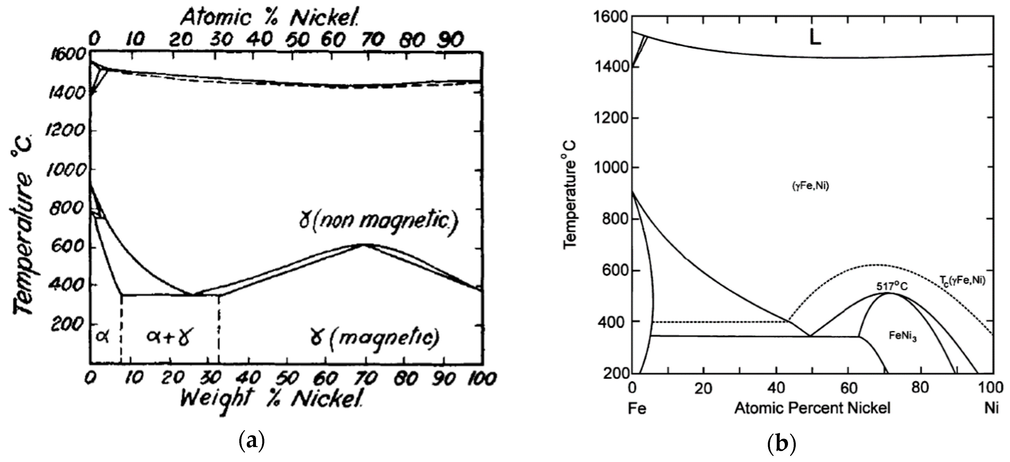
Both nickel and manganese, if added in sufficiently high concentration, completely eliminate the bcc α-iron phase and replace it, down to room temperature, with the γ-phase. So nickel and manganese depress the phase transformation from γ to α to lower temperatures (Fig. 1a), i.e. both Ac 1 and Ac 3 are lowered.

Equilibrium phase diagram for Iron-Nickel-Chromium alloy ...
The geometry of the temperature–composition phase diagram of iron–nickel alloys suggests that the hcp–fcc–liquid triple point is located at 10 to 20 wt.% Ni at the pressure of the inner core boundary. The fcc phase could crystallize depending on the nickel and silicon contents in the Earth's core, both of which are fcc stabilizer. Previous article
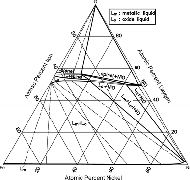
Fe-Ni-O (Iron-Nickel-Oxygen) | SpringerLink
[8] Compared to the phase diagram of pure Fe [Hemley and Mao, 2001], it is evident that the stability field of the fcc phase can be extended to higher pressures and lower temperatures with the addition of Ni (Figure 1). However, the effect of Ni on the phase diagram of Fe is not as dramatic as the addition of silicon in Fe [Lin et al., 2002].

Magnetic phase diagram of the Fe–Ni system - ScienceDirect
The geometry of the temperature-composition phase diagram of iron-nickel alloys suggests that the hcp-fcc-liquid triple point is located at 10 to 20 wt.% Ni at the pressure of the inner core boundary. The fcc phase could crystallize depending on the nickel and silicon contents in the Earth's core, both of which are fcc stabilizer.

Fe-Ni-Si (Iron-Nickel-Silicon) | SpringerLink
The phase relations of an Fe10wt%Ni alloy were investigated in a diamond anvil cell up to 86 GPa and 2382 K. Adding nickel into iron stabilizes the fcc phase to higher pressures and lower temperatures compared to pure iron, and a region of two-phase coexistence between fcc and hcp phases is observed.

Influence of Alloying Elements on Steel Microstructure ...
This document is part of Volume 11 `Ternary Alloy Systems: Phase Diagrams, Crystallographic and Thermodynamic Data', Subvolume D `Iron Systems', of Landolt-Börnstein - Group IV `Physical Chemistry'.
1 a)Aluminum Nickel Phase diagram b)Aluminum Iron Phase ...
γ-phase alloy and iron is connected to α→ε phase transition in it at pressure 13 GPа. For consideration of the formed contradictions of these data sets we carried out some additional ex-speriment determination of parameters of shock compression of iron and iron-nickel alloy (stainless steel) corresponding to a melting at normal pressure
![Fe-Ni phase diagram. [16] | Download Scientific Diagram](https://www.researchgate.net/profile/Rcs-Navarro/publication/286807012/figure/fig2/AS:587504373731328@1517083366646/Hydrogen-equilibrium-mole-fraction-as-function-of-the-temperature-for-the-iron-and_Q320.jpg)
Fe-Ni phase diagram. [16] | Download Scientific Diagram
For example, in the iron carbon phase diagram, addition of nickel lowers the A3 boundary while the addition of chromium raises it. Eutectic Point Eutectic point is a point where multiple phases meet. For the iron-carbon alloy diagram, the eutectic point is where the lines A1, A3 and ACM meet. The formation of these points is coincidental.

Phase diagram of Ni-C (left) and (Fe-15Ni)-C (right ...
Iron-Carbon Phase Diagram • Pure iron experiences two changes in crystal structure before it melts.--At room temperature the stable form, ferrite with BCC crystal structure.--Ferrite experiences a polymorphic transformation to FCC austenite at 912°C. • At 1394°C, FCC austenite reverts back to BCC! ferrite phase, which finally melts at ...

Phases and the Phase Diagram - ppt video online download
Iron-nickel (Fe-Ni) alloy is the most abundant component in the Earth's core [1]. The amount ofNi in the core is about 5.5wt%, on the basis of geochemical models [2]. The phase diagram and physical properties of Fe have been extensively studied [3]. Iron crystallizes in the bcc structure under ambient conditions, and it
Teach Yourself Phase Diagrams and Phase Transformations
Phase Diagram Resources from ASM International. Alloy phase diagrams and crystal structure data are used by metallurgists, materials engineers, and materials scientists to develop new alloys for specific applications; fabricate these alloys into useful configurations; design and control heat treatment procedures for alloys that will produce the required mechanical, physical, and chemical ...
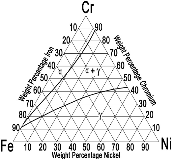
Ternary Diagram for Wrought Austenitic Stainless Steels

Determination of the iron rich portion of the iron - nickel ...

Binary Phase Diagrams In Metallurgy - MechanicalBase
Compilative Fe – Ni phase diagram with author's correction ...
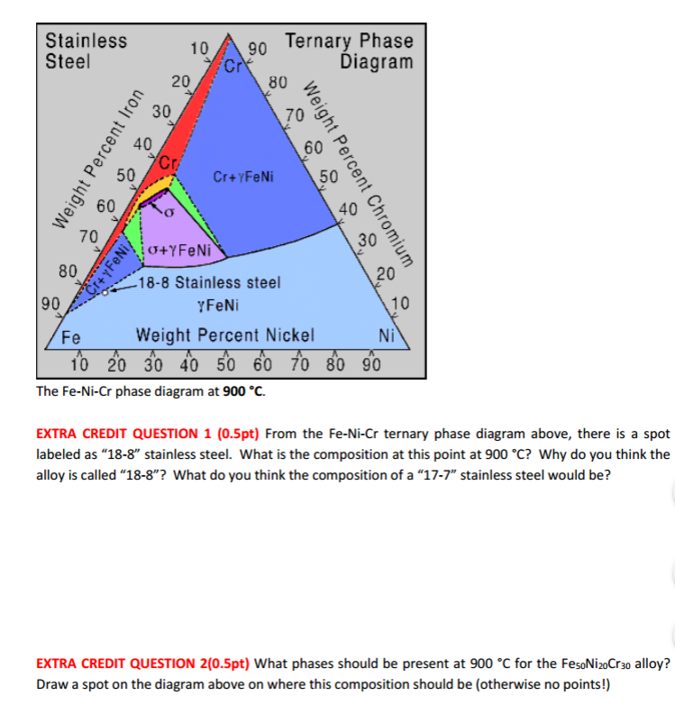
Solved From the Fe-Ni-Cr ternary phase diagram above, there ...

File:Magnesium-Lithium phase diagram.png - Wikiversity
![PDF] Iron--Nickel--Tungsten Phase Diagram. | Semantic Scholar](https://d3i71xaburhd42.cloudfront.net/edc9875279dacf5a2d776176d80c985c14c96fc5/14-Figure3-1.png)
PDF] Iron--Nickel--Tungsten Phase Diagram. | Semantic Scholar

Structure, Microstructure, and Some Selected Mechanical ...
Teach Yourself Phase Diagrams and Phase Transformations
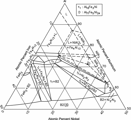
Al-Fe-Ni (Aluminum-Iron-Nickel) | SpringerLink
Chapter 8 Phase Diagrams

Iron-Nickel Alloys - an overview | ScienceDirect Topics
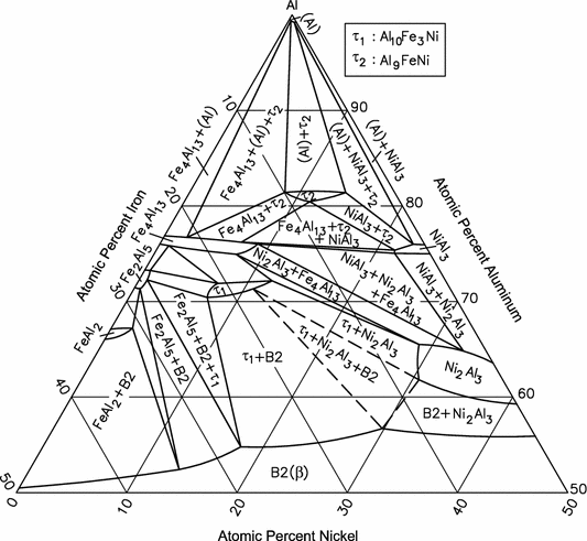
Al-Fe-Ni (Aluminum-Iron-Nickel) | SpringerLink

Determination of the iron rich portion of the iron - nickel ...
Thermodynamics at the nanoscale: phase diagrams of nickel ...

Allotropes of iron - Wikipedia
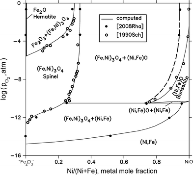
Fe-Ni-O (Iron-Nickel-Oxygen) | SpringerLink

Iron-Nickel Alloys - an overview | ScienceDirect Topics
Schaeffler, De Long, and WRC welding diagrams - which steels ...
![Fe-Ni phase diagram. [16] | Download Scientific Diagram](https://www.researchgate.net/profile/Rcs-Navarro/publication/286807012/figure/fig3/AS:587504373760005@1517083366669/Fe-Ni-phase-diagram-16_Q640.jpg)
Fe-Ni phase diagram. [16] | Download Scientific Diagram

Representative phase diagram of iron and iron-nickel alloys ...
![6 Phase diagram of Fe-Ni alloys ([8]) | Download Scientific ...](https://www.researchgate.net/profile/Ratchatee-Techapiesancharoenkij/publication/37598297/figure/fig4/AS:309877667844098@1450892001328/Phase-diagram-of-Fe-Ni-alloys-8.png)
6 Phase diagram of Fe-Ni alloys ([8]) | Download Scientific ...
Chapter 9: Phase Diagrams
![Iron-Carbon Phase Diagram Explained [with Graphs]](https://fractory.com/wp-content/uploads/2020/03/Iron-carbon-phase-diagram-explained.jpg)
Iron-Carbon Phase Diagram Explained [with Graphs]
Allotropes of iron - Wikipedia

Binary Alloys - an overview | ScienceDirect Topics


Comments
Post a Comment