42 shear and moment diagram example problems with solutions
PDF_C8_b (Shear Forces and Bending Moments in Beams) Q6: A simply supported beam with a triangularly distributed downward load is shown in Fig. Calculate reaction; draw shear force diagram; find location of V=0; calculate maximum moment, and draw the moment diagram. 6k/ft 9 ft RA = (27k)(9-6)/9= 9k A B F = (0.5x6x9) = 27k x = (2/3)(9) = 6 ft Relevant Equations: M = Fd = 0. Fy = 0. Part of a project I am working on (part #3…see description below) is asking us to find the internal loads (shear and moment) and draw the corresponding shear/moment diagrams of the control arm shown below. It's a little tricky to me, because all of the members associated with these type of problems ...
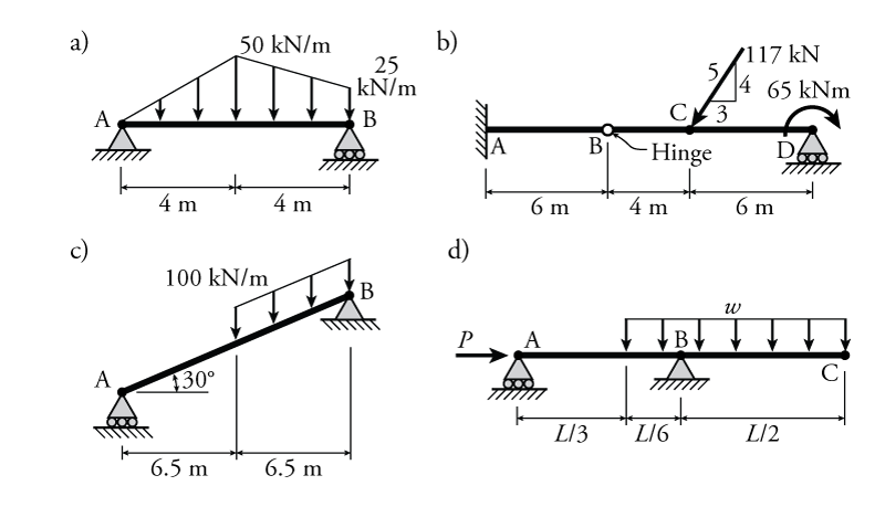
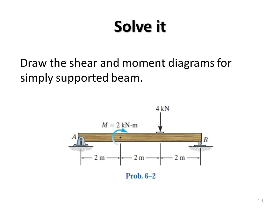
Write shear and moment equations for the beams in the following problems. In each problem, let x be the distance measured from left end of the beam. Also, draw shear and moment diagrams, specifying values at all change of loading positions and at points of zero shear.
Shear and moment diagram example problems with solutions
Shear and bending moment diagrams are analytical tools used in conjunction with structural analysis to help perform structural design by determining the value of shear force and bending moment at a given point of a structural element such as a beam.These diagrams can be used to easily determine the type, size, and material of a member in a structure so that a given set of loads can be ... Selected Problem Answers. For each beam shown below, determine the equations for the axial force, shear force and bending moment as a function of the position along the length of the beam. Use these equations to draw the axial force diagram, shear force diagram, and bending moment diagram. Mar 05, 2021 · (M/EI) diagram. First, draw the bending moment diagram for the beam and divide it by the flexural rigidity, EI, to obtain the diagram shown in Figure 7.10b. Slope at A. The slope at the free end is equal to the area of the diagram between A and B, according to the first moment-area theorem.
Shear and moment diagram example problems with solutions. Solutions to the problems of the 5-th International Physics Olympiad, 1971, Sofia, Bulgaria The problems and the solutions are adapted by Victor Ivanov Sofia State University, Faculty of Physics, 5 James Bourcier Blvd., 1164 Sofia, Bulgaria Reference: O. F. Kabardin, V. A. Orlov, in “International Physics Olympiads for High School Students ... Basic Example to Construct a Shear and Moment Diagram : Constructing shear and moment diagrams is similar to finding the shear and moment at a particular point on a beam structure. However, instead of using an exact location, the location is a variable distance 'x'. This allows the shear and moment to be a function of the distance, x. Solution: To draw the shear force diagram and bending moment diagram we need R A and R B. Fig. 19.4 Shear force and bending moment. By taking moment of all the forces about point A. We get R B × 10 - 8 × 9 - 2 × 4 × 5 - 4 × 2 = 0 . R B = 12 kN . From condition of static equilibrium ΣFy = 0 . R A + R B - 4 - 8 - 8 = 0 . R A ... This website is great; the best one that I have found so far to draw shear force and bending moment diagrams. Three ways in which it could be improved: 1) Allow a distributed load to be inputted as an equation i.e. more complex distributed load. 2) Calculate the shear force and bending moment diagrams for frames as well.
CE 331, Fall 2007 Shear & Moment Diagrams Examples 6 / 7 Example Problem 2. (same as Problem 1 except overhang = 7ft) • uniform distributed dead load (wD) = 0.50klf applied to entire beam • uniform distributed live load (wL) = 1.00klf applied along either Span 1 only, Span 2 only, or Spans 1 and 2 MD: max MD = 12.46k-ft in "middle" of Span 1 10.5 Practice Problems. Selected Problem Answers. For the beams shown below determine the reaction forces and draw the shear and moment diagrams using the moment distribution method. All elements have the same E I unless otherwise indicated. Solve Problem 1 (b) for the loading shown with the addition of a support settlement of 20 m m at support ... 20 Nov 2016 — collection of solved problems and examples in civil engineering, Solution of selected problems on Shear force and bending moment diagrams. Being able to draw shear force diagrams (SFD) and bending moment diagrams (BMD) is a critical skill for any student studying statics, mechanics of materials, or structural engineering. There is a long way and a quick way to do them.
Molecular dynamics and Monte Carlo methods will be covered in detail. Applications of these techniques to some example problems in materials science, mechanical deformation, dislocation interactions, nucleation/growth of phases, melting solidification structures, and point defects are presented. MAE 261. Cardiovascular Fluid Mechanics (4) Numerical Problems Multiple Choice Questions 9. Shear Force and Bending Moment Diagrams 9.1 Beams 9.2 Types of Beams 9.3 Types of Loads and Beams 9.4 Shear Force and Bending Moment 9.5 Shear Force Diagram (SFD) and Bending Moment Diagram (BMD) 9.6 Sign Convention of Shear Force and Bending Moment in SFD and BMD Click to get the latest Buzzing content. Sign up for your weekly dose of feel-good entertainment and movie content! Problem 6: Bending Moment Diagram ... Problem 10: Bending Moment and Shear force ... Once a free body diagram is prepared, the solution is found out by ...25 pages Euler–Bernoulli beam theory (also known as engineer's beam theory or classical beam theory) is a simplification of the linear theory of elasticity which provides a means of calculating the load-carrying and deflection ...
How to Draw Shear Force & Bending Moment Diagram | Simply ...
The two expressions above give the value of the internal shear force and bending moment in the beam, between the distances of the 10 ft. and 20 ft. A useful way to visualize this information is to make Shear Force and Bending Moment Diagrams - which are really the graphs of the shear force and bending moment expressions over the length of the beam.
Solution to Problem 403 | Shear and Moment Diagrams ...
Statics of Bending: Shear and Bending Moment Diagrams David Roylance Department of Materials Science and Engineering Massachusetts Institute of Technology
Shear and Moment Diagram Example 3 - Mechanics of Materials
Engineering mechanics solved problems pdf. Provide Data. Download PDF. Download Full PDF Package. This paper. A short summary of this paper. 14 Full PDFs related to this paper. READ PAPER. Engineering mechanics solved problems pdf. Download. Engineering mechanics solved problems pdf.
Mechanics of Materials Chapter 4 Shear and Moment In Beams
The shear force diagram is a straight line between the points (0, 13.16) and (5.6, -13.16). The bending moment diagram can be calculated directly but is more easily given by the area under the shear force diagram. Bending moments for distributed loads are quadratic functions (they are the integrals of the shear force function).
How to Draw Shear Force & Bending Moment Diagram | Simply ...
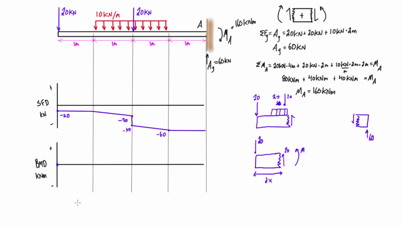
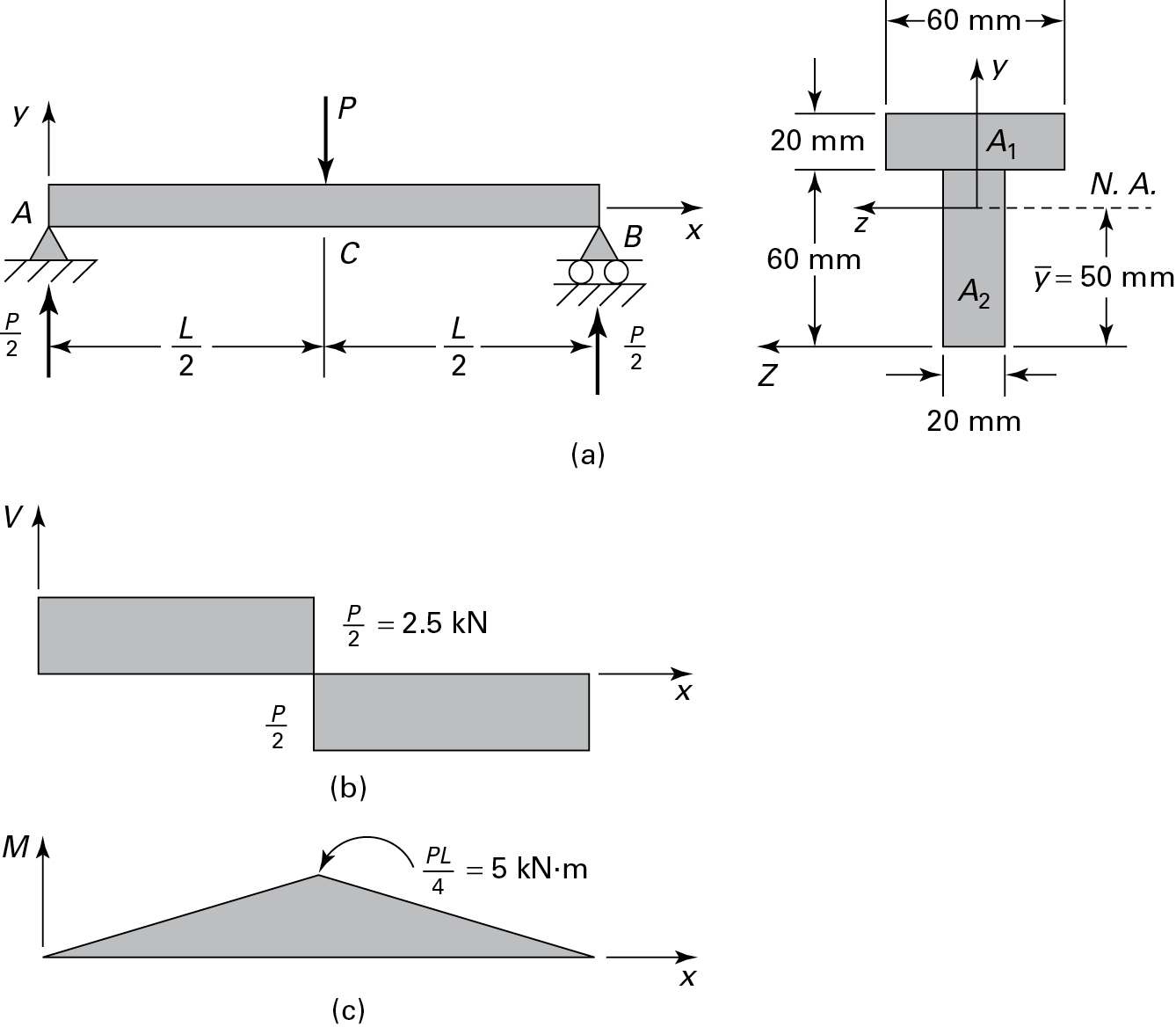
Shear and moment diagram example problems with solutions pdf In the previous example problem, Shear and Bending Moment Diagrams Example 1 (FEIM): Draw the shear and bending moment diagrams for the following beam. Professional Publications, Inc. FERC Mechanics of Materials 13-4c2 Beams Shear is undefined at concentrated force points, but just short of x = …

Shear Force And Bending Moment Diagrams Graphical Method ...
Civil Engineering questions and answers. PROBLEM 9: Draw the shear and moment diagram of the frame shown in the figure determine the maximum positive and negative moment of each member. compute also for the axial force on member Ae and Bc. 10KN 15 kH fm ī D E 9m 7m 4kW/m 12 kN/m t 10m 5m PROBLEM 2 Draw the shear and moment diagram of the frame ...
Shear force and bending moment diagram practice problem #5
analysis because only one set of solutions is required and it is applicable to almost all problems. Solutions for deflection and moment for constant values of k, and also for a stepped variation ink, are available (2). The case where the soil to a depth of 0.4R has a modulus equal to 0.5k (Fig. 4a) is a better approximation for preloaded cohesive
Beams – SFD and BMD
Problem 403 Beam loaded as shown in Fig. P-403. [collapse collapsed title="Click here to read or hide the general instruction"]Write shear and moment equations for the beams in the following problems. In each problem, let x be the distance measured from left end of the beam. Also, draw shear and moment diagrams, specifying values at all change of loading positions and at

How to Solve a Shear and Moment Problem : 7 Steps - Instructables
Solution Procedure I . Examine the component and determine the Knowns and Unknowns 2. Draw a FBD and apply Equilibrium (Sum Of Force and Moments) to solve for the Reactions 3. Draw the Shear, Normal, and Bending Moment Diagrams 4. Identify the critial locations, x along the structure where Vmax, Nmax, and Mmax exist. 5. Identify which stresses ...
4.5 Practice Problems | Learn About Structures
Problem 4.3-1 Calculate the shear force V and bending moment M Solution 4.3-3 Beam with overhangs. 260 .. 4.5-1 through 4.5-10 are symbolic problems and Probs. Draw the shear-force and bending-moment diagrams for this beam. bending moment.

Moment Diagrams Constructed by the Method of Superposition ...
Solution to problem 11-23, shear and bending moment diagram with variable distributed load
Bending Shear and Moment Diagram, Graphical method to ...
Maximum Shear Stresses, τ max, at Angle, θ τ-max : Like the normal stress, the shear stress will also have a maximum at a given angle, θ τ-max. This angle can be determined by taking a derivative of the shear stress rotation equation with respect to the angle and set equate to zero.
Beam Formulas for Multiple Point Loads. - Structural ...
4.4 Area Method for Drawing Shear- Moment Diagrams Useful relationships between the loading, shear force, and bending moment can be derived from the equilibrium equations. These relationships enable us to plot the shear force diagram directly from the load diagram, and then construct the bending moment diagram from the shear force diagram.
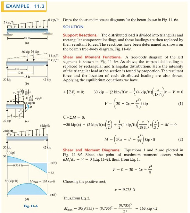
Solved EXAMPLE 11.3 6 kip/ft Draw the shear and moment ...
Problem 10: Bending Moment and Shear force A beam with a hinge is loaded as above. Draw the shear force and bending moment diagram. Solution: Concept: A hinge can transfer axial force and shear force but not bending moment. So, bending moment at the hinge location is zero. Also, without the hinge, the system is statically indeterminate (to a ...

Mechanics eBook: Shear/Moment Diagrams
Calculate the shear force and bending moment for the beam subjected to an uniformly distributed load as shown in the figure, then draw the shear force diagram (SFD) and bending moment diagram (BMD). 5 kN/m 3 m A B EXAMPLE 6
Relationship Between Load, Shear, and Moment | Strength of ...
Aug 03, 2021 · Draw one bending moment and one shearing force diagram for the given beam by combining the diagrams in step 9. ... Practice Problems. 12.1 Use the moment distribution method to compute the end moment of members of the beams shown in Figure P12.1 through Figure P12.12 and draw the bending moment and shear force diagrams. EI = constant. Fig. …
Shear force and bending moment diagram
Shear Moment, and Axial Diagrams Now that the shear and moment is known for each section of the ladder, the results can be plotted. The resulting graphics are called the shear diagram and moment diagram. Since the same x was used for all three sections, the each equation for each section can be easily plotted as shown at the left. Failure in Shear
Shear-Force and Bending-Moment Diagrams To solve the problems ...
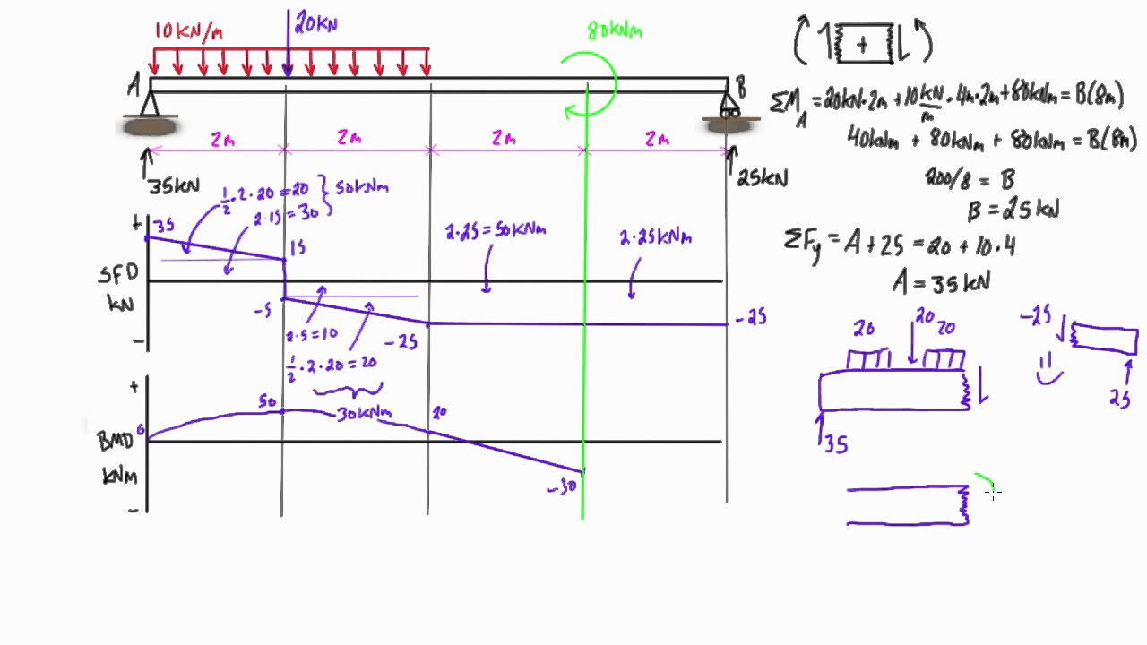
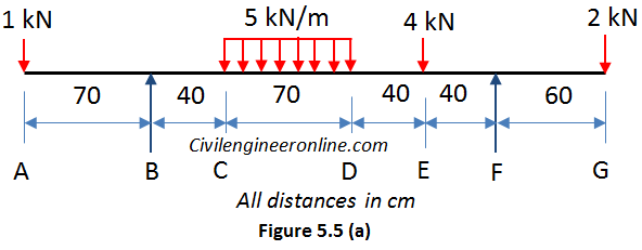
According to the shear diagram depicted in Fig. 5.5, this information is shown on the shear diagram (c). Diagram of Bending Moments, as an example. Making use of the same sections and coordinates that were used earlier to compute shear, we can derive the following equations for bending moment in each of the four segments of the beam.

Shear and moment diagram - Wikipedia
•Write shear and moment equations for the beams in the following problems. In each problem, let x be the distance measured from left end of the beam. Also, draw shear and moment diagrams, specifying values at all change of loading positions and at points of zero shear. Neglect the mass of the beam in each problem. 2

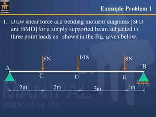
1. Draw a shear force and bending moment diagram for the beam ...
7.15) of simply supported columns, where, according to the Euler-Bernoulli beam theory, shear deformations were neglected. Now, we investigate the effect of shear deformations on the buckling load. The equations of a Timoshenko beam, that is, a bar with shear deformations, are given in Table 3.3 (page 95).
Mechanics of Materials Chapter 4 Shear and Moment In Beams
Download the DegreeTutors Guide to Shear and Moment Diagrams eBook. 📓. This is a problem. Without understanding the shear forces and bending moments developed in a structure you can’t complete a design. Shear force and bending moment diagrams tell us about the underlying state of stress in the structure. So naturally they’re the starting ...
Shear force and bending moment diagram practice problem #4
Beams and bending moments Lesson 19SOLVED EXAMPLES BASED ON SHEAR FORCE AND BENDING MOMENT DIAGRAMS 19.1 Problem A cantilever beam is subjected to various loads as shown in figure. Draw the shear force diagram and bending moment diagram for the beam. Fig. 19.1 Shear force and bending moment Solution: Consider a section (X - X') at a ...

Bending Moment Diagram - an overview | ScienceDirect Topics
Civil Engineering questions and answers. PROBLEM 1 Draw the shear and moment diagram of the frame shown in the figure Determine the maximum positive and negative moment if each member. compute also for the axial force on member A c and Bc. 15 kN/m 10 KH D E 7m am Alnim 12 kH/m B DO rom 5m | PROBLEM 2: Draw the shear and moment diagram of the ...
Shear force and bending moment diagram practice problem #9
Shear and Moment Diagram of First Floor (BC). ... since the beginning of the 20th century as environmental problems have become social and economic problems. The importance of EGSS became clear ...
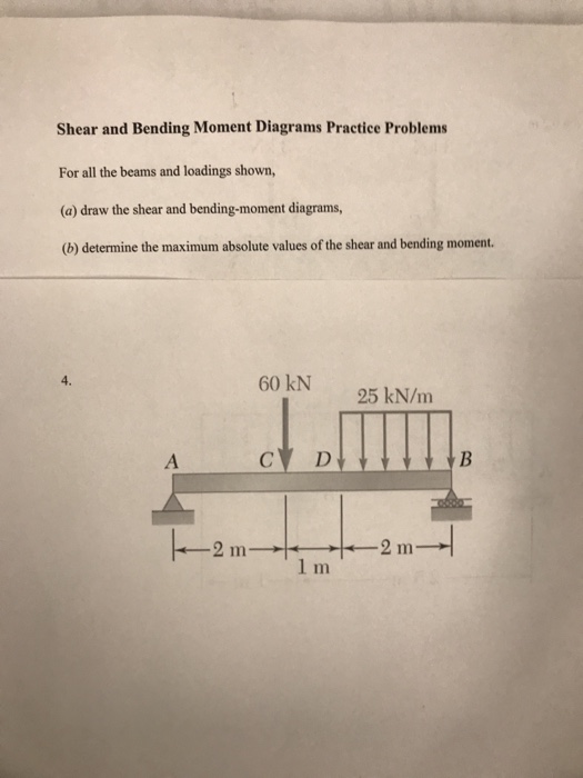
Solved Shear and Bending Moment Diagrams Practice Problems ...
Mar 05, 2021 · (M/EI) diagram. First, draw the bending moment diagram for the beam and divide it by the flexural rigidity, EI, to obtain the diagram shown in Figure 7.10b. Slope at A. The slope at the free end is equal to the area of the diagram between A and B, according to the first moment-area theorem.
Module -4 Shear Force and Bending Moment Diagrams
Selected Problem Answers. For each beam shown below, determine the equations for the axial force, shear force and bending moment as a function of the position along the length of the beam. Use these equations to draw the axial force diagram, shear force diagram, and bending moment diagram.
Civil Engineering - Solved Examples for shear force and ...
Shear and bending moment diagrams are analytical tools used in conjunction with structural analysis to help perform structural design by determining the value of shear force and bending moment at a given point of a structural element such as a beam.These diagrams can be used to easily determine the type, size, and material of a member in a structure so that a given set of loads can be ...
DE-12: Lesson 19. SOLVED EXAMPLES BASED ON SHEAR FORCE AND ...
Shear Force and Bending Moment Diagrams SFD BMD

Shear Force And Bending Moment Diagrams Graphical Method ...

Draw the shear force and bending moment diagrams for the beam ...

Ultimate Guide to Shear Force and Bending Moment Diagrams ...

4.5 Practice Problems | Learn About Structures

Beam Reactions and Diagrams – Strength of Materials ...

Statics eBook: Shear, Moment and Load Relations

Drawing Shear and Moment Diagrams for Beam

Shear Force and Bending Moment Diagrams - Wikiversity
Solution to Problem 415 | Shear and Moment Diagrams ...
Chapter 4: Internal Forces in Beams and Frames†in ...
Bending Moment & shear force
Bending Moment & shear force
5.7 Normal and Shear Stresses | Bending of Beams | InformIT


Comments
Post a Comment