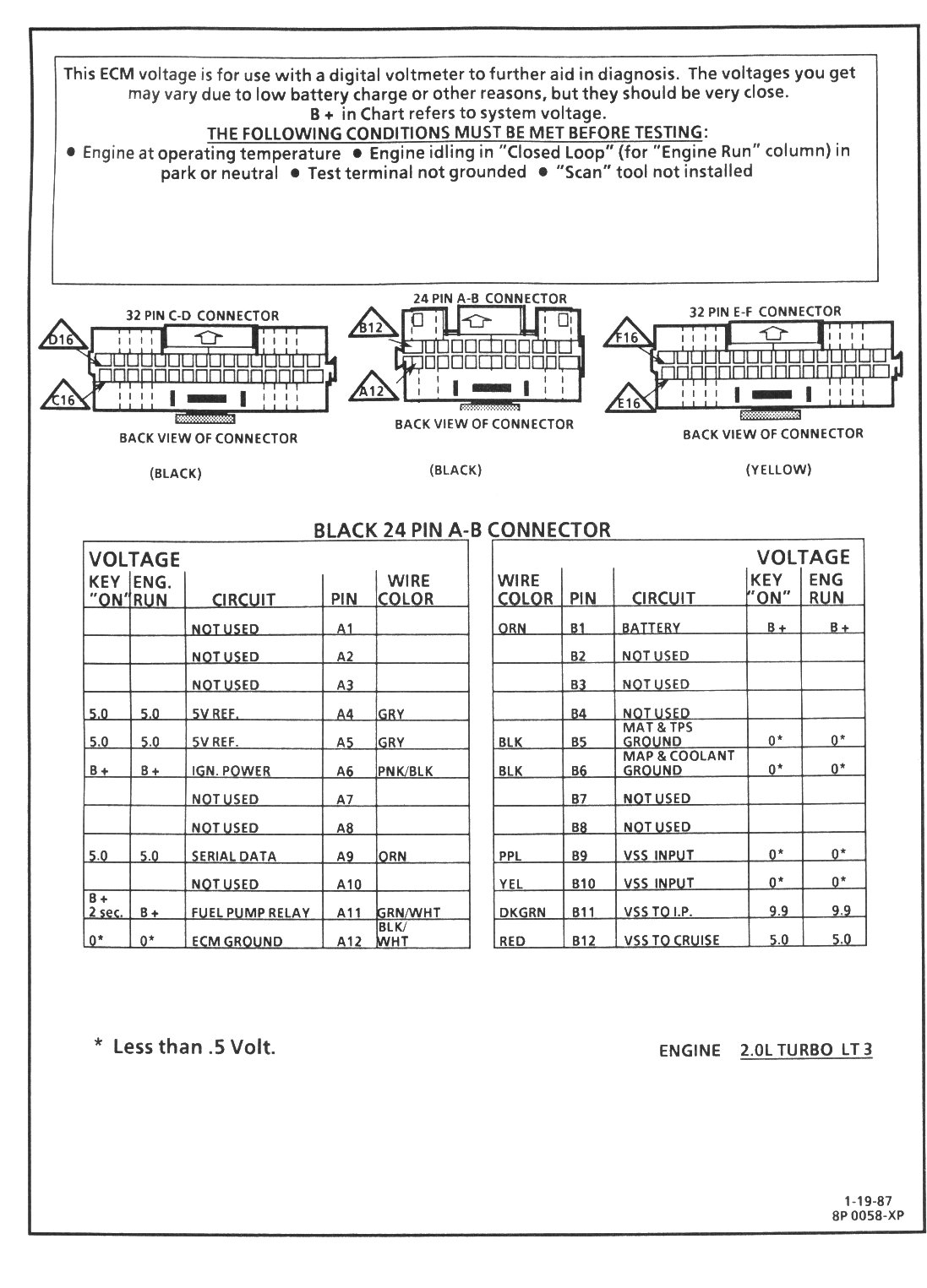
43 ddec 4 ecm wiring diagram
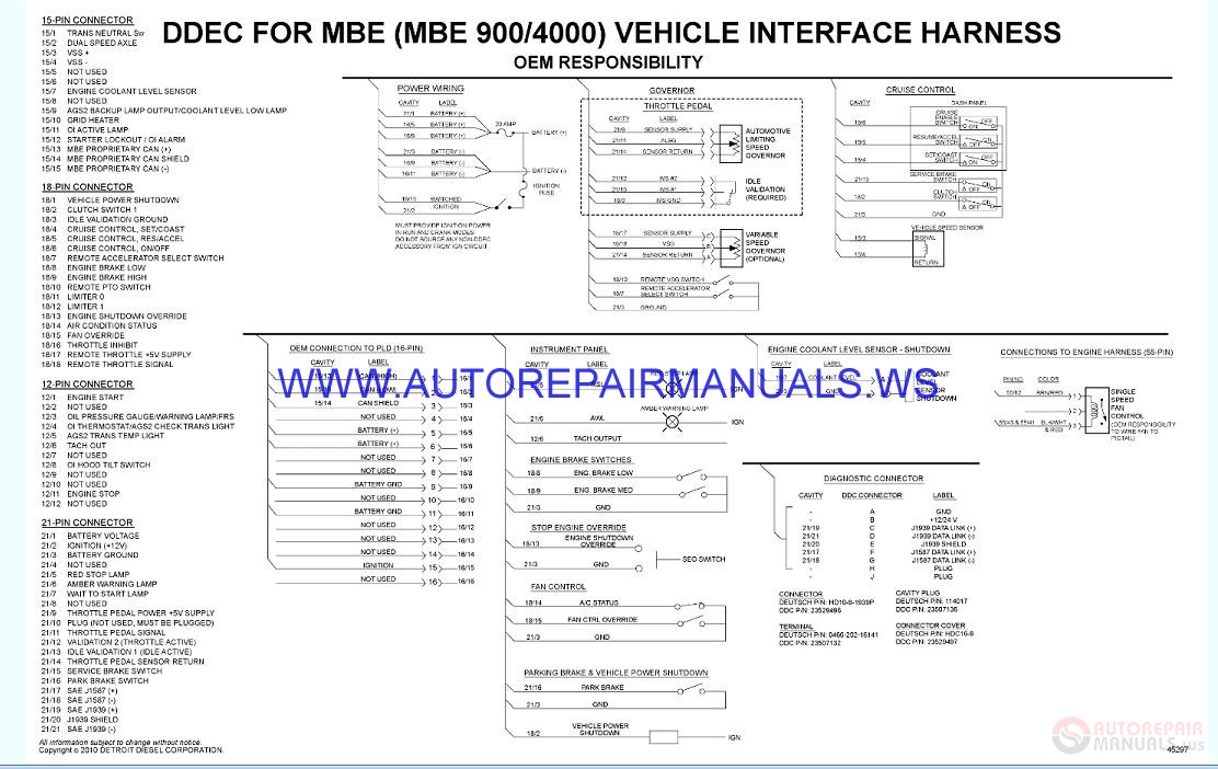
HARDWARE AND WIRING DDEC V supports three independent data links. There are two links on the Vehicle Interface Harness (VIH). One link is based on SAE J1708, and the second is SAE J1939. The other link, on the Engine Harness, is CAN based and will be used for proprietary communications such as Ddec 3 Ecm Wiring Diagram DDEC III/IV SINGLE ECM TROUBLESHOOTING GUIDE For the sensor locations for the Series 60, 2002 EGR engine, see Figure 3-3. 1. EGR Valve 9. EGR Temperature Sensor 2. VNT 10. Turbo Boost Sensor 3. Turbo Compressor Outlet Temp Sensor (TCO) 11. Intake Air Temp Sensor 4. Oil Temperature Sensor 12. Oil Pressure Sensor 5 ...
Jan 02, 2020 · Detroit Ddec 4 Ecm Wiring Diagram– wiring diagram is a simplified within acceptable limits pictorial representation of an electrical circuit.It shows the components of the circuit as simplified shapes, and the capability and signal connections along with the devices.
Ddec 4 ecm wiring diagram
Source. detroit diesel series 60 ecm wiring diagram inspiration ddec iii iv kenworth t wiring diagram detroit.The Detroit Diesel Series 60 DDEC III, IV, V, VI Wiring Diagrams are also known as Electrical Schematics or Circuit Diagrams. The wiring diagrams cover both the Series 60 engine harness and Series 60 vehicle interface harness. 14 ddec 4 ecm wiring diagram car cable and detroit diesel series 60 best. This video shows you how to wire the ecm on a series 60 ddec iv engine. Here is a i am going to attach a diagram of the engine harness also, so you can check the srs and trs wires. Can anyone help me unlock the password on a detroit series 60. Laminated factory Detroit Diesel DDEC 4 ECM wire diagram. Shows ECM & wiring to & from the ECM. Includes connections, wires, sensors, input & controlled devices. Excellent for diagnostics. Laminated factory Detroit Diesel DDEC 4 ECM wire diagram. For 2003 & newer DDEC 4 EGR engines. Included: ECM ECM wiring Connections Wires Sensors
Ddec 4 ecm wiring diagram. The Detroit Diesel Series 60 DDEC III, IV, V, VI Wiring Diagrams are also known as Electrical Schematics or Circuit Diagrams. The wiring diagrams cover both the Series 60 engine harness and Series 60 vehicle interface harness. List of files in the Detroit Series 60 Wiring Diagram. DDEC I, DDEC II, and DDEC III & IV Schematics. Diagrama De Cabina Oem Ddec V 10 3 Vi Wiring Diagram 5 Wikiduh Com With 4 Ecm. 14 ddec 4 ecm wiring diagram car cable and detroit diesel series 60 best. DDEC V provides an indication of engine and vehicle malfunctions. The ECU continually monitors the DDEC V system. Any faults that occur are. Detroit Ddec 4 Ecm Wiring Diagram- wiring diagram is a simplified within acceptable limits pictorial representation of an electrical circuit.It shows the components of the circuit as simplified shapes, and the capability and signal connections along with the devices. The original wiring from batteries to ecm. Dt466 sensor wiring harness diagram thank you for visiting our site, this is images about dt466 sensor wiring harness diagram posted by brenda botha in dt466 category on . I need an accurate wiring diagram for my 2004 international 4300 with the dt466 engine.
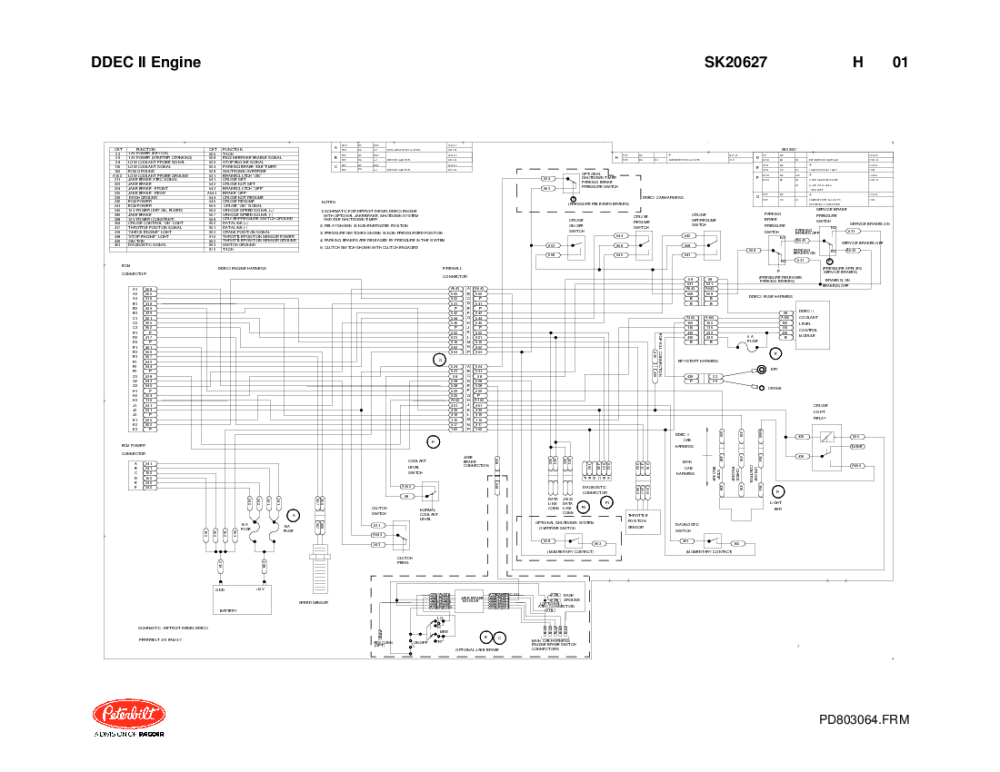
Fig. 4, Detroit Diesel Series 50 and 60 Engines With DDEC III Wiring Diagram (engine-harness side) 54.17 Detroit Diesel Electronic Controls (DDEC ® ) Wiring 400/4 Heavy-Duty Trucks Service Manual, Supplement 23, December 1999 Detroit Diesel Series 60 DDEC IV Wiring Diagram On Detroit Diesel Series 60 Ecm Wiring Find this Pin and more on v1 by Victor Catandica. Detroit Diesel Detroit Motors Dodge Ram Diesel Cummins Diesel Electronic Control Unit Electrical Circuit Diagram Picture Wire House Wiring Free Printables 3.2.2 ECM PART NUMBERS Part numbers for DDEC III and IV ECMs are listed in Table 3-3. Part Number Description Voltage No. of Cylinders 23518645* DDEC III - Standard On-highway ECM 12/24 V 6 23518743 DDEC III - Universal ECM 12/24 V 8 23518744 DDEC III - Series 4000 ECM only 24 V 8 23519307 DDEC IV - Standard On-highway ECM 12 V 6 One ecm is called the master while the others are referred to as receivers. The detroit diesel series 60 ddec iii iv v vi wiring diagrams are also known as electrical schematics or circuit diagrams. Engine Sensor Locations On A Detroit Dd13 Get Free Image Freightliner Detroit Engineering Here is a simple wiring diagram for …
Detroit Ddec 4 Ecm Wiring Diagram- wiring diagram is a simplified within acceptable limits pictorial representation of an electrical circuit.It shows the components of the circuit as simplified shapes, and the capability and signal connections along with the devices. of 1 CONNECTOR DDC P/N 12015378 TERMINAL DDC P/N 12089188 NOTE: FUSE MUST BE PLACED BETWEEN MATING CONNECTOR AND BATTERY CONNECTOR DDC P/N: 12129615 TERMINAL DDC P/N: 12045773 CABLE SEAL DDC P/N: 12052924 SECONDARY LOCK DDC P/N: 12052845 MUST PROVIDE IGNITION POWER IN RUN AND CRANK MODES. DO NOT SOURCE ANY ACCESSORY FROM CIRCUIT 439 OFF ON 14 Ddec 4 Ecm Wiring Diagram Car Cable And Detroit Diesel Series 60 On Detroit Diesel Series 60 Ecm Wiring Find this Pin and more on Quick Savesby chance aguirri. More like this Dodge Ram Diesel Detroit Diesel Multi Colored Eyes House Wiring Cummins Free Pictures No Response Cool Photos Wire 14 Ddec 4 Ecm Wiring Diagram Car Cable And Detroit Diesel Series 60 On Detroit Diesel Series 60 Ecm Wiring Detroit Diesel Dodge Ram Diesel House Wiring . Detroit Diesel Epa Ddec Meb Series50 60 Wiring Diagrams Manual 2003 Auto Repair Manual Forum Heavy Equipment Forums Download Repair Workshop Manual .
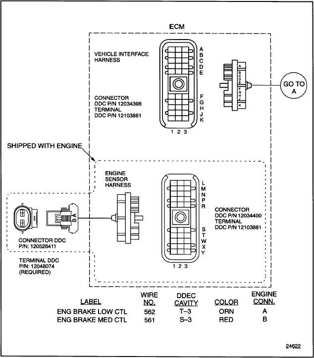
INTERNAL ENGINE BRAKE FOR DDEC SYSTEM ECM
4. Loosen the wire harness connector hold-down screws, gently disengage connectors, and remove DDEC II ECM from vehicle. DDEC IV ECM Installation Conversion kit components are listed in Table 1. Refer to the Series 60 Service Manual and install parts as follows: 1. Install the Engine Sensor Harness (P/N: 23513558), included in the kit. See ...
Detroit Diesel EPA-DDEC-MEB-Series50-60 Wiring Diagrams ...
precuations, followed by hardware and wiring requirements, inputs and outputs, and available features. The second portion covers communication protocol. The third portion covers the tools capable of obtaining engine data and diagnostic information from the Electronic Control Module, as well as reprogramming of its key parameters.
DDEC IV On-Highway - ddcsn
HARDWARE AND WIRING The part numbers for the 31-pin MCM pigtail connector are listed in Table 3-15. Part DDC Part Number Connector 008 545 31 26 Terminal 006 545 52 26 Seals 000 545 72 80 Cavity Plugs 000 545 62 80 Backshell 000 546 99 35 Table 3-15 31-pin MCM Pigtail Connector Part Numbers
Detroit Diesel Series 60 DDEC III, IV, V, VI Wiring Diagrams - MyPowerManual
a.2 Removal of the DDEC V Electronic Control Unit Perform the following steps for ECU removal: 1. Remove screw from center of shroud and connector. Oct 27, · These are the pin numbers on the DDEC III and DDEC IV vehicle connector on your ECM. The vehicle harness plugs into this connector.

Ddec IV Oem Wiring Diagram PDF | PDF | Electrical Connector ...
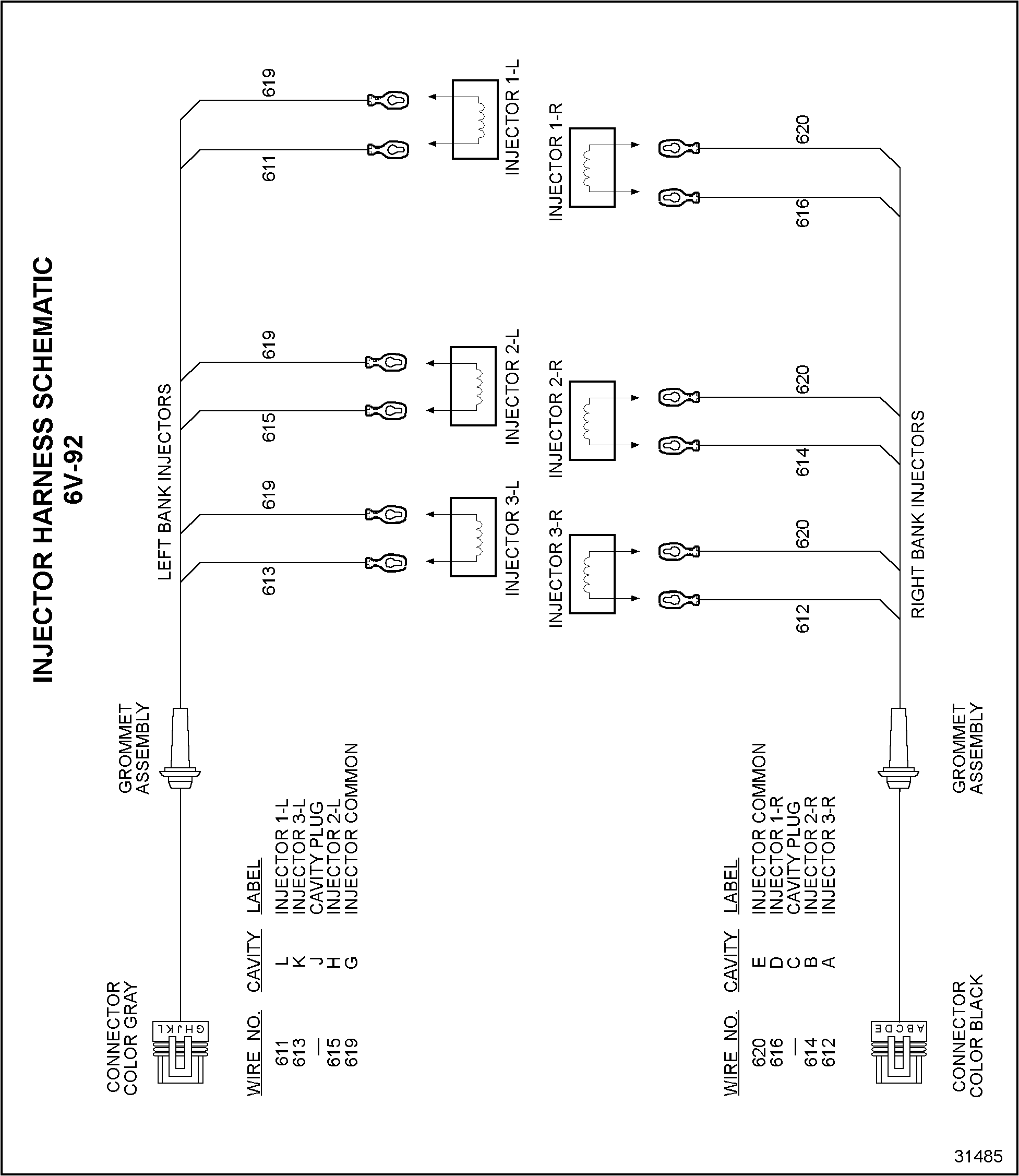
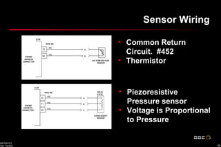
92.4 INJECTOR HARNESS WIRING SCHEMATIC - 8V149 ENGINES DDEC TROUBLESHOOTING MANUAL SERIES 8V92 AND 31484 92-7 The following wire schematics support the injector harness; see Figure 92-5. oo Figure 92—5 00000 00000 Injector Harness — U.' O o
Ddec iv on highway - egr application and installation
Jan 30, 2019 · The DDEC II ECM . Ddec 3 ecm wiring diagram along with 60 series ddec iii wiring diagram also ddec 5 ecm wiring diagram along with diagramm ofenverkabelung ge jbp68hd1cc in addition misfiring cylinder together with 60 series injector wiring harness also carrier ac parts diagram as well as kenworth t trailer wiring diagram further atv wiring ...

27 Detroit Diesel Engine Service Manuals Free Download ...
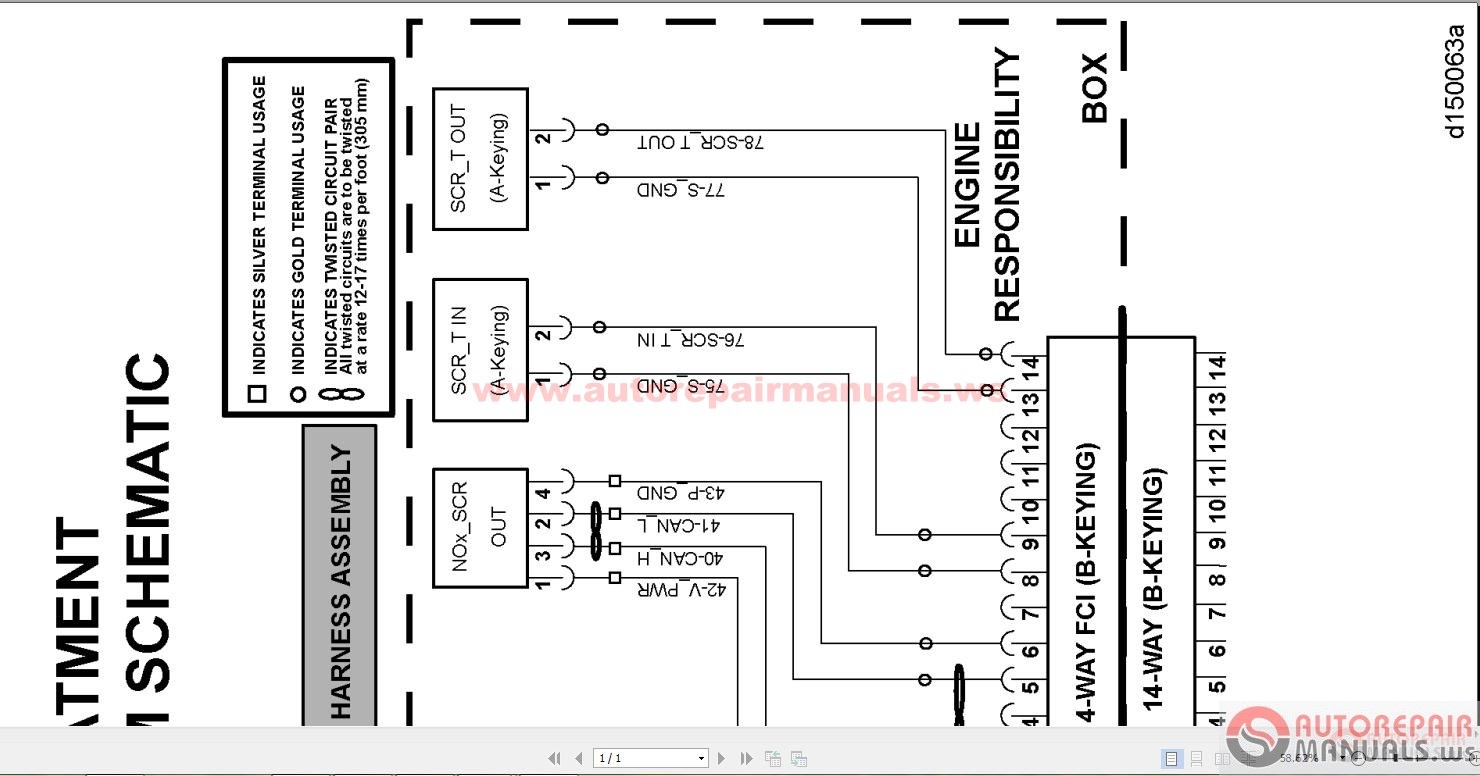
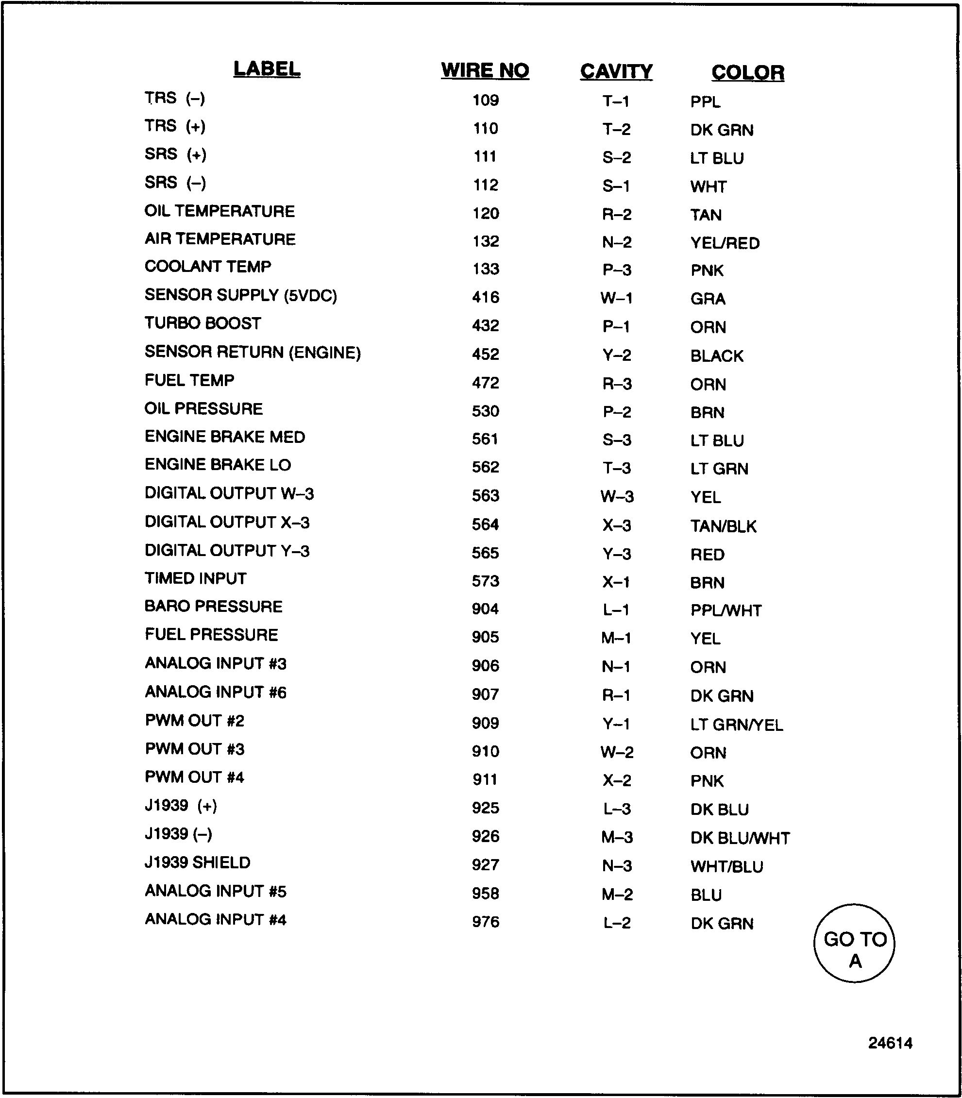
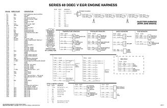
® ddec v wiring diagram pin no. wire color description pin no 1 color wht description inj common 1,2,3 grommet assembly ddc responsibility 2 wht inj common 4,5,6 e-1 blk egr hydraulic valve control e-2 wht air temp 3 wht inj 1 e-67 wht 1 e-66 wht 1 e-68 wht 1 e-64 wht 1 e-65 wht 1 e-63 wht 1 inj inj inj inj inj inj e-3 - spare 4 wht

DETROIT Wiring Diagrams - Blog.Teknisi
The ECM Lab - The Detroit Diesel Series 60 DDEC IV ECM The ECM Lab - The Detroit Diesel Series 60 DDEC IV ECM Watch later Watch on See Fig.2 and Fig.3 for partial (detailed) views of the full view of the DDEC II wiring diagram. See Fig.4 for a full view of the DDEC III wiring diagram (the engine side).

DDEC IV ECM Detroit Diesel common inspection/testing
Laminated factory Detroit Diesel DDEC 3 &; 4 ECM wire diagram. Shows ECM & wiring to & from the ECM. Includes connections, wires, sensors, input & controlled devices. Excellent for diagnostics. Laminated factory Detroit Diesel DDEC 3 &; 4 ECM wire diagram for non-EGR engines. Included: ECM & ECM wiring Connections Wires Sensors

Detroit Diesel electronic items and manuals
ecm connector ecm power connector a543 555 p 541 p 542 544 545 p 901 916 952 953 a543 555 902 541 p 542 ... 4 1 7 9 5 2 9 5 2 4 1 7 1 6 throttle position sensor 68 a150 150 115 68 531 a543 558 439 b b b 68 531 a543 ... service brakes on parking brakes on service brakes off a150 150 115 439 439 b ddec ii coolant level control module 4 39 p 2 29 ...

Motor S-50 Ddec-Iv | PDF | Electrical Connector | Turbocharger
Description : This manual provides troubleshooting, codes and wiring diagrams for Detroit single ECM DDEC III and DDEC IV control systems. The DDEC III/IV single ECM troubleshooting manual is bookmarked, searchable and printable. Detroit Diesel DDEC 3, DDEC 4 Troubleshooting PDF Manual ...

Figure 2-4. DDEC II Injector Harness Wiring Schematic
Laminated factory Detroit Diesel DDEC 4 ECM wire diagram. Shows ECM & wiring to & from the ECM. Includes connections, wires, sensors, input & controlled devices. Excellent for diagnostics. Laminated factory Detroit Diesel DDEC 4 ECM wire diagram. For 2003 & newer DDEC 4 EGR engines. Included: ECM ECM wiring Connections Wires Sensors
Series 60 EGR - Section 10.4.7 DDEC IV ECM Overview and ...
14 ddec 4 ecm wiring diagram car cable and detroit diesel series 60 best. This video shows you how to wire the ecm on a series 60 ddec iv engine. Here is a i am going to attach a diagram of the engine harness also, so you can check the srs and trs wires. Can anyone help me unlock the password on a detroit series 60.
DDEC III/IV Single ECM Troubleshooting - Section 92.3 ...
Source. detroit diesel series 60 ecm wiring diagram inspiration ddec iii iv kenworth t wiring diagram detroit.The Detroit Diesel Series 60 DDEC III, IV, V, VI Wiring Diagrams are also known as Electrical Schematics or Circuit Diagrams. The wiring diagrams cover both the Series 60 engine harness and Series 60 vehicle interface harness.
2.16 DDEC III/IV ELECTRONIC CONTROL MODULE
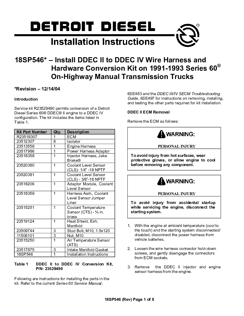
Install DDEC II to DDEC IV Wire Harness and - pdf Docer.com.ar
749 Problems

Detroit Diesel Wiring Diagrams All Years
Install DDEC II to DDEC IV Wire Harness and - pdf Docer.com.ar

Series 60 - CRUISE CONTROL - DDEC VI SCHEMATICS - Detroit ...
Detroit Wiring Diagrams | Auto Repair Manual Forum - Heavy ...

ECM Circuit & Wiring Diagram
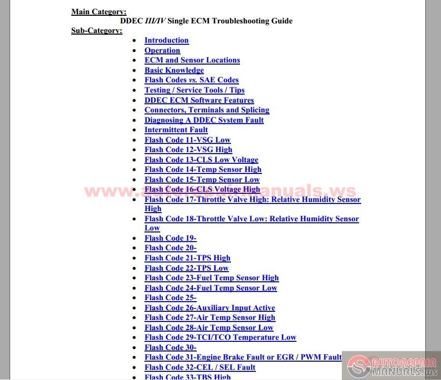
Detroit Diesel - DDEC III - IV Single ECM Troubleshooting ...
![Data Codes Ddec Iii And Iv. [pon2rk98j0l0]](https://idoc.pub/img/crop/300x300/od4p2g1wq9np.jpg)
Data Codes Ddec Iii And Iv. [pon2rk98j0l0]

Ddec IV Oem Wiring Diagram PDF | PDF | Electrical Connector ...

Caterpillar Shematics Electrical Wiring Diagram - Truck ...

Detroit Diesel Service & Repair manuals - Free Download pdf ...
Detroit Diesel DDC-DDEC II Wiring Diagram - pdf Docer.com.ar

I am working on a series 60 detroit that cylinders 1, 2, &3 ...
Series 60 EGR - Section 10.4.7 DDEC IV ECM Overview and ...
Ddec master 2000 current4 6

DETROIT Wiring Diagrams - Blog.Teknisi

DETROIT DIESEL DDEC Multi-ECM Troubleshooting Manual 6SE496 ...

DETROIT Wiring Diagrams - Blog.Teknisi
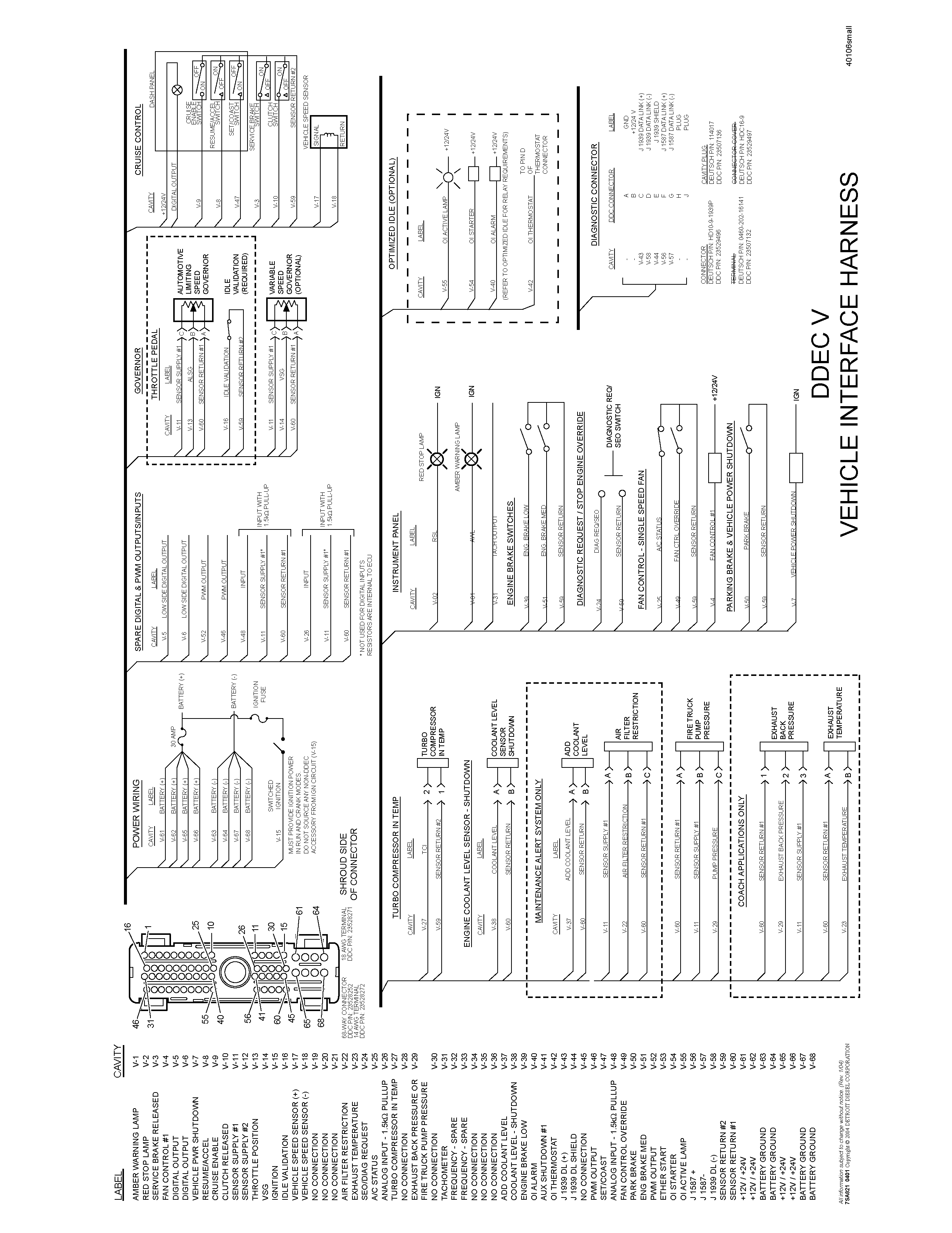
Series 60 EGR - Section 10.4.7 DDEC IV Wiring Schematics ...

PDF) DDEC IV ON-HIGHWAY -EGR APPLICATION AND INSTALLATION ...

Details about Detroit Diesel DDEC III IV w/ Jake Brake Engine/Cab Wiring Diagrams OTH-0007
![Serie 60 Ddec IV Egr Harnes Del Vehiculo [1] - [PDF Document]](https://demo.fdocuments.in/img/378x509/reader024/reader/2021021811/545ecdaab1af9ff0588b49ad/r-1.jpg)
Serie 60 Ddec IV Egr Harnes Del Vehiculo [1] - [PDF Document]
Detroit Diesel DDEC V EGR with Jake Brake Engine/Cab Wiring ...

Series 60 EGR - Section 10.4.7 DDEC IV ECM Overview and ...

Series 60 EGR - Section 10.4.7 DDEC IV ECM Overview and ...
![Detroit Ddec Multi-ecm Troubleshooting Manual.pdf [en5k03q8vxno]](https://idoc.pub/img/crop/300x300/3no7mpjozeld.jpg)
Detroit Ddec Multi-ecm Troubleshooting Manual.pdf [en5k03q8vxno]

Ddec IV Oem Wiring Diagram PDF | PDF | Electrical Connector ...


Comments
Post a Comment