43 enthalpy pressure diagram
The pressure-enthalpy diagram (log P/h diagram) is a very useful tool for refrigerant technicians, engineers and researchers. Since it's not always possible to have all of these diagrams together, we decided to give you this complete pack. An example of a diagram based on specific enthalpy (abscissa) and pressure (ordinate) can be seen above. For a refrigerant the typically applicable interval for pressure is large - and therefore diagrams use a logarithmic scale for pressure. The diagram is arranged so that it displays the liquid, vapour and mixture regions for the refrigerant.
Commonly used Mollier diagrams are the enthalpy-entropy (or h-s) diagram ( below) and the pressure-enthalpy diagram illustrated at the bottom of this page. The Enthapy-Entropy or h-s diagram: The h-s diagram is one in which Enthalpy values form the vertical axis and Entropy the horizontal axis.

Enthalpy pressure diagram
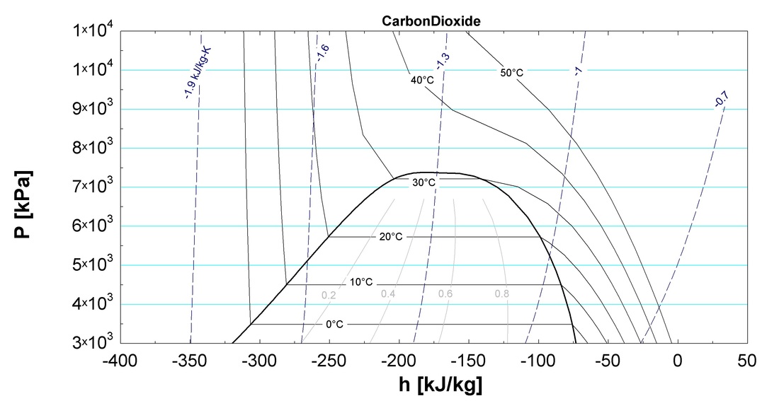
Carbon Dioxide: Pressure - Enthalpy Diagram Melting Line-40 o -40 C-2 0-2 0. Title: mollier_chart_met.xls Created Date: 11/10/1999 5:42:45 PM Pressure / Enthalpy Diagram Example. This article was written by my buddy and Canadian Supertech Tim Tanguay. Thanks, Tim! This P/E chart shows R410a at 100°F saturated condensing temp, 10°F SC, 40°F saturated suction temp, 20°F SH at the compressor. The green highlighted thumb shape is the saturation zone. Pressure-Enthalpy Diagram S=Specific Entropy, kJ/kg*K T=Temperature, ºC Ethane Produced by I. Aartun, NTNU 2002. Based on the program Allprops, Center for Applied Thermodynamic Studies, University of Idaho. Title: etan.PDF Author: Ingrid Aartun Created Date: 22. March 2002 13:34
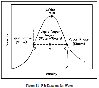
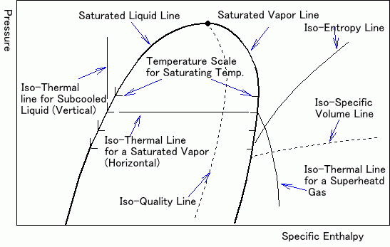
Enthalpy pressure diagram. Explains parts of the pressure-enthalpy diagram for a single-component system and discusses how enthalpy depends on pressure for water. Made by faculty at th... The enthalpy H of a thermodynamic system is defined as the sum of its internal energy and the product of its pressure and volume: H = U + pV, where U is the internal energy, p is pressure, and V is the volume of the system. Enthalpy is an extensive property; it is proportional to the size of the system (for homogeneous systems). In refrigeration technology, the pressure-enthalpy diagram is by far the most frequently used state diagram. The pressure is mostly scaled logarithmically, hence the name log ph diagram. Isolines and the vapor dome. The thermodynamic properties of a refrigerant are represented in the state diagram as lines of constant state variables - so ... The pressure-enthalpy diagram (log P/h diagram) is a very useful tool for refrigerant technicians. First, an explanation of how the diagram is built up is given, and then its use is describ ed. Figure 2.1 shows the principle of a log P/h diagram, and indicates the refrigerant's various thermodynamic states. This diagram can be seen as a map of the refrigerant.
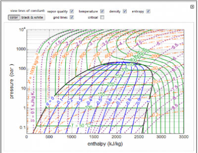
enthalpy (PH) diagram, and the pressure-internal-energy (PU) diagram. Sketching property diagrams for chemical mixtures such as temperature-composition (TXY), pressure-composition (PXY), and enthalpy-composition (HXY) diagrams will be covered under other documents. Appendix D: Pressure−Enthalpy Diagrams for Various Compounds FIGURE D.1 Oxygen pressure-enthalpy diagram. (Adapted from Canjar, L.N. and Manning, F.S., Thermodynamic Properties and Reduced Correlations for Gases, Gulf Publishing, Houston, … - Selection from Chemical Engineering Fluid Mechanics, 3rd Edition [Book] This screencast has been updated. Please see the revised version here: https://youtu.be/jGIHNKLMLCY Made by faculty at the University of Colorado Boulder, D... This Demonstration shows a pressure-enthalpy () diagram for water. Check and uncheck the boxes to add or remove a property from the diagram. You can show lines of constant vapor quality (blue), temperature (green), density (orange, dashed) and entropy (purple, dashed). You can show grid lines using a checkbox.
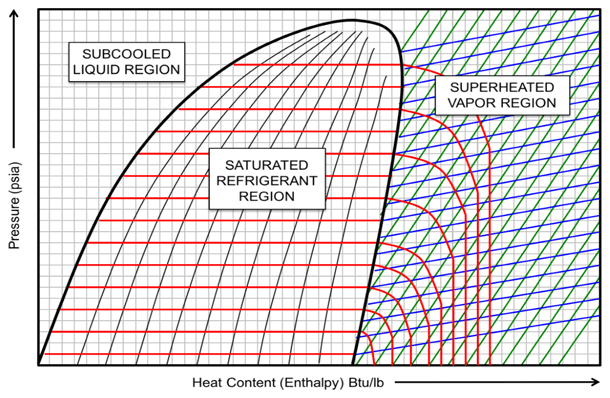
The pressure-enthalpy chart, as shown in Fig. 2, displays all the pertinent properties for a given refrigerant (in this example R22). The bubble to the left is the portion of the diagram where the refrigerant is in the saturated condition. The blue line on the left of the bubble represents the 100% saturated liquid line, Enthalpy: Enthalpy is defined as the total heat content or total useful energy of a substance. The symbol for enthalpy is "h." Enthalpy is also considered to be the sum of internal energy "u" and flow energy (or flow work) p.V. This definition of enthalpy can be expressed, mathematically, as follows: h = u + p.V Eq. 1.1 Where, tecquipment.com Pressure-Enthalpy chart, R-134a (1,1,1,2-tetrafluoroethane) Enthalpy (kJ/Kg) Pressure (Bar) Pressure (MPa) Produced by TecQuipment's VDAS ® system On the pressure-enthalpy diagram superheat is shown as horizontal movement along the suction pressure line passed the 100% vapor curve. The figure on the following page shows the difference between 0 °F and 15 °F superheat. Point B is the 100% vapor point at a constant evaporator/suction pressure of 36.8 psia and a temperature of 25 °F.

Pressure Enthalpy Chart
How to Read a Pressure-Enthalpy Diagram In chemical engineering, it is often necessary to know how properties like pressure, enthalpy, volume, and entropy relate to each other at a certain temperature. A Pressure-Enthalpy Diagram provides this information but can be cryptic to decipher. What you need to know: Liquid/vapor dome region

Pressure-Enthalpy As A Service Tool | ACHR News
The most common type of pressure-enthalpy diagram is shown in Figures 1A through 1H. They show all five properties for a specific refrigerant in present-day use. Pressure is listed along the right and left borders in psia. Horizontal lines are constant pressure lines. Enthalpy is listed along the bottom and top of the diagram.

Pressure Enthalpy Chart
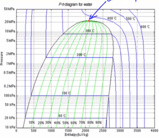
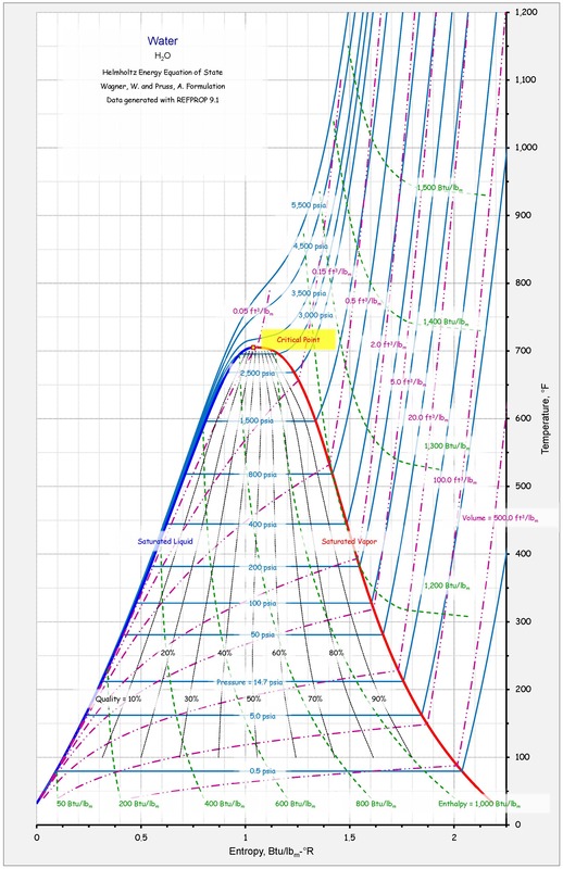
Pressure-Enthalpy Diagram for Water - Ohio University
Tutorial: Pressure-Enthalpy Diagrams | AIChE
R744 (CO2) Pressure Enthalpy Chart. Download a PDF copy of the pressure enthalpy chart for both Metric and Imperial Units.

Category: Using Pressure Enthalpy Diagrams - FUNDAMENTAL ...
4.88 pressure-enthalpy diagram for ethylene 10 100 1000 10000 700 750 800 850 900 950 1000 1050 1100 1150 1200 enthalpy, Btu/lb pressure (psia) 160 F 140 F 120 F 100 F 80 F 60 F 40 F 20 F 0 F 20 F 240 F 200 F 100 F 0 F 100 F 200 F 300 F liquid liquid-vapor two phase vapor psia = pounds per square inch absolute
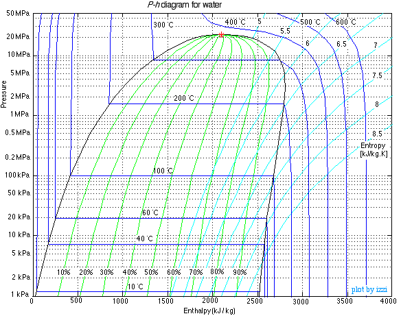
Steam Property Tables | Thermodynamics
An enthalpy-entropy chart, also known as the H-S chart or Mollier diagram, plots the total heat against entropy, describing the enthalpy of a thermodynamic system. A typical chart covers a pressure range of .01-1000 bar, and temperatures up to 800 degrees Celsius. It shows enthalpy in terms of internal energy, pressure and volume using the relationship = + (or, in terms of specific ...
Pressure Enthalpy (P-h) Diagram - Thermodynamics ...
pressure-enthalpy and temperature-entropy diagrams Appears in CYCLE_D-HX: NIST Vapor Compression Cycle Model Accounting for Refrigerant Thermodynamic and Transport Properties

Pressure-Enthalpy Diagram, Property Diagrams and Steam tables ...
pressure. To convert from Gauge to Absolute add 15 to the Gauge pressure. PSIA is the " Pressure " reference of the "Pressure Enthalpy" diagram The enthalpy scale is shown at the bottom of the diagram. Any movement to the right indicates an increase in enthalpy. Enthalpy is defined as: Total heat in a substance above an accepted base temperature.
Pressure Enthalpy Without Tears
The pressure-enthalpy diagram (log P/h diagram) is a very useful tool for refrigerant technicians. First, an explanation of how the diagram is built up is ...

File:Pressure-enthalpy chart for steam, in US units.svg ...
Enthalpy Pressure Diagram. This web page allows one to select a pure component or a mixture of components and produce a graph of enthalpy vs. pressure with lines of constant temperature. There is also a line for the phase envelope. This page uses the Peng-Robinson equation of state to predict the properties of these mixtures.
PRESSURE-ENTHALPY CHARTS AND THEIR USE INTRODUCTION The ...
Jan 07, 2014 · This video explains the parts of a pressure-enthalpy diagram for a single-component system and discusses how enthalpy depends on pressure for water. If these diagrams are a breeze for you, or you're just looking for help with another concept, check out other chemical engineering tutorials in the Learn ChemE Engineering Screencast series .
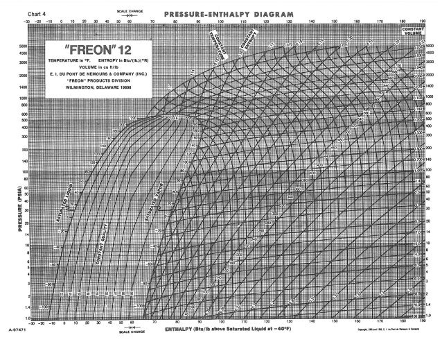
FREON"12 PRESSURE ENTHALPY DIAGRAM
Pressure-Enthalpy Diagram S=Specific Entropy, kJ/kg*K T=Temperature, ºC Ethane Produced by I. Aartun, NTNU 2002. Based on the program Allprops, Center for Applied Thermodynamic Studies, University of Idaho. Title: etan.PDF Author: Ingrid Aartun Created Date: 22. March 2002 13:34

How do you read a pressure enthalpy chart?
Pressure / Enthalpy Diagram Example. This article was written by my buddy and Canadian Supertech Tim Tanguay. Thanks, Tim! This P/E chart shows R410a at 100°F saturated condensing temp, 10°F SC, 40°F saturated suction temp, 20°F SH at the compressor. The green highlighted thumb shape is the saturation zone.
Thermodynamic Diagrams Spreadsheet
Carbon Dioxide: Pressure - Enthalpy Diagram Melting Line-40 o -40 C-2 0-2 0. Title: mollier_chart_met.xls Created Date: 11/10/1999 5:42:45 PM

Pressure Enthalpy Charts | Industrial Controls
Solved 501. An ammonia (R-717) refrigerant brine chiller ...
thermodynamic-properties-phase-diagrams-interactive ...
DuPont™ ISCEON® MO79 (R-422A) Pressure-Enthalpy Diagram

REFRIGERANTS P-H DIAGRAM - Refrigeration - HVAC/R and Solar ...
Blog - Jingwei Zhu
JSRAE, Japanese Society for Refrigerating and AirConditioning ...
Engineering Thermodynamics A Graphical Approach
Thermodynamics Glossary - Pressure-Enthalpy Diagram

Carbon Dioxide: Pressure - Enthalpy Diagram - … | Pressure ...
Pressure-Enthalpy Diagram for Water - Wolfram Demonstrations ...

Pressure-enthalpy diagram of thermodynamic mixture identified ...

Appendix D: Pressure–Enthalpy Diagrams for Various Compounds ...
PRESSURE-ENTHALPY CHARTS AND THEIR USE INTRODUCTION The ...

2.1 The pressure-enthalpy diagram - SWEP

File:Pressure-enthalpy chart for steam, in US units.svg ...

Pressure-enthalpy diagram for R-22 showing inlet and outlet ...

R245fa Pressure-Enthalpy diagram | Download Scientific Diagram

Pressure / Enthalpy Diagram Example - HVAC School

Pressure Enthalpy chart

10 9 8 R-134a 7 Pressure-Enthalpy Diagram - .Pressure ...

REFRIGERATION

Thermodynamic scope for two-phase fluid networks - MATLAB
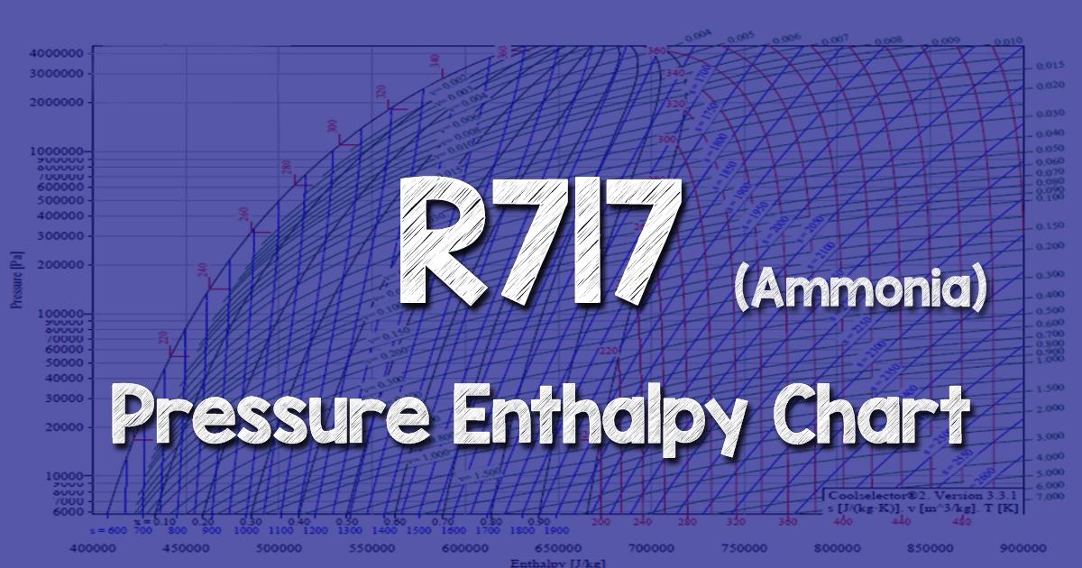
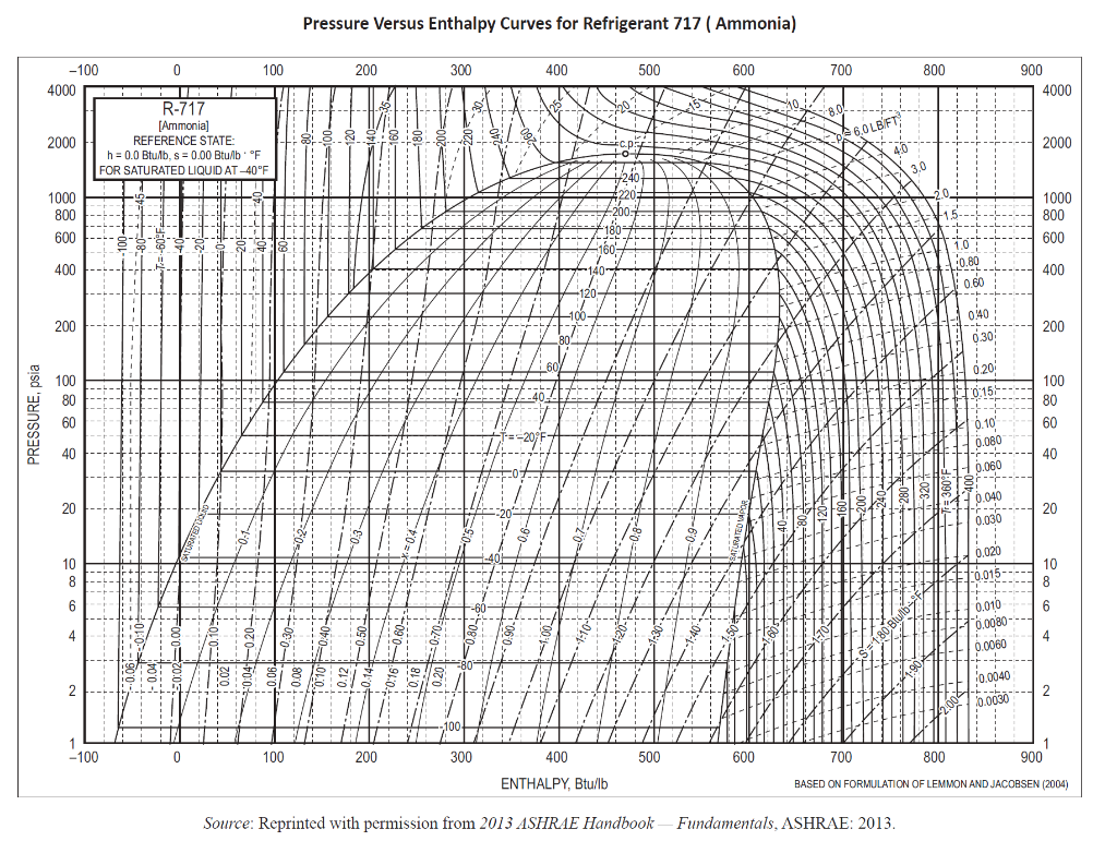
R717 (Ammonia) Pressure Enthalpy Chart - The Engineering Mindset

2.1 The pressure-enthalpy diagram - SWEP
Pressure-enthalpy Diagram For Water And Steam Based On The ...

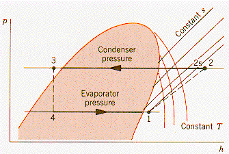
Pressure-enthalpy diagram for a standard vapor-compression ...
Testing of a 4 K to 2 K heat exchanger with an intermediate ...

Diagram enthalpy-pressure - Big Chemical Encyclopedia


Comments
Post a Comment