39 tilt and trim switch wiring diagram
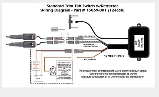
Bally/Stern - PinWiki Feb 05, 2022 · A single signal is sent to the self test switch from the U10 PIA on the CPU board via connection A4J3-1, and returned to ground via a connection A3J2-7 on the solenoid driver board. Also, the switch commonly referred to as "switch 33" on a Bally or Stern CPU board, and used to reset audits and bookkeeping, is not part of the switch matrix either. how to wire tilt and trim switch - shapovmusic.com How do you wire a trim sender? How do you calibrate trim senders? On the transom/trim bracket, port side. If analog as you said, raise motor up so that pads are just touching trim rods. Loosen two screws on sending unit and adjust sender until gauge reads full trim. Tighten screws and recheck trim reading through full stroke.
360° Mounted White Motion Sensor Fixture - The Home Depot Aug 05, 2020 · Maestro 2 Amp Single-Pole Motion Sensor Switch, White Let Lutrons Maestro Occupancy Sensing Switch Let Lutrons Maestro Occupancy Sensing Switch turn the lights on and off for you. This sensor is a simple way to save energy and add light automation to any room of your home, turning lights on when you enter the room and off when you exit.

Tilt and trim switch wiring diagram
There are two aileron trim switches to prevent spurious ... Mar 11, 2022 · Tilt Trim Switch-Power Tilt and Trim for Outboard Switch - Trim Switch 703-82563-02-00 Tilt Trim Switch Remote Control Assembly 703-82563-01-00 for Yamaha Engine Outboard Motors Universal 5. When this happens, the performance, safety, and efficiency of the boat are compromised. hydraulischem powertilt und hydraulischen schnellwechsler (. 3 Wire Tilt Trim Diagram - justussocializing.org 3 Wire Tilt Trim Diagram- One of the most hard automotive fix tasks that a mechanic or fix shop can resign yourself to is the wiring, or rewiring of a car's electrical system.The hardship really is that every car is different. afterward grating to remove, replace or fix the wiring in an automobile, having an accurate and detailed 3 wire tilt trim diagram is essential to the success of the ... Alpha One Trim Sender Wiring Diagram Aug 25, · Re: Mercruiser trim/tilt wiring For the position sender, the diagram shows one side to ground, and the other side to a brown/white wire, that goes to the connector, and on up to the trim gauge. Look on the back of the gauge and see if there is a br/w wire there. The Trim Limit Switch is mounted to the Port side of the Gimbal Ring.
Tilt and trim switch wiring diagram. Flour Mill Rye [4MH368] Search: Rye Flour Mill. What is Rye Flour Mill. Every flour has its own unique properties. Sourdough Rye using your flour and some crushed organic caraway seeds has lifted my Sourdough Rye to a new level!! Mercruiser Power Trim Limit Switch Wiring Diagram Power Trim and Tilt Systems The MerCruiser power trim system permits sub-system consists of a power trim control panel or handle, a pump motor and a trim limit switch, with connecting wiring. Some models may also be equipped with a trim indicator sender. Figure 1 shows a typical system. Troubleshooting: Trim/Tilt Does not Work Mercury 90 Hp Wiring Diagram - The Wiring Tilt and Trim Switch Wiring Diagram Best Trim and Hydraulics Need. Collection of wiring diagram for mercury outboard motor. Where To Hook Tach To On Ignition Key Switch On An Omc . Also SELOC manuals has a Mercury Outboards Manual #1408, that covers 1965-1989, 90-300HP, Inline 6 and V-6, 2-Stroke Models. Tilt And Trim Switch Wiring Diagram - easywiring Tilt and trim switch wiring diagram wiring diagram is a simplified standard pictorial representation of an electrical circuit it shows the components of the circuit as simplified shapes and the facility and signal links together with the devices. Awesome Evinrude Power Tilt Trim Wiring Diagram In 2020 Boat Wiring Diagram Outboard
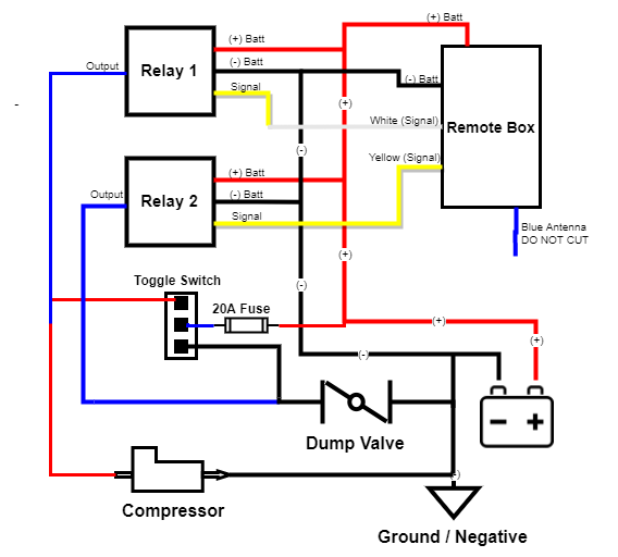
2 Wire Trim Motor Wiring Diagram - Studying Diagrams Common Outboard Motor Trim And Tilt System Wiring Diagrams Mastertech Marine. To the bluewhite wire and on to the solenoid to drive the unit to its full up position. The relays are quivalent to heavy duty single pole double throw switches. You will need switches capable of handling 50Ams of power or more. Mercury Outboard Trim Wiring Diagram Mercruiser sterndrive power trim and tilt diode module for duel … The best different is always to use a verified and accurate mercury outboard trim wiring diagram that's provided from a trusted source. A good, expected company that has a long track tape of providing the most up-to-date wiring diagrams to hand is not hard to find. How to Wire a Toggle Switch to the Power Tilt and Trim ... Wiring a toggle switch to the power tilt and trim is a fairly straightforward job. Loosen and disconnect the positive and negative cables from the battery, using the adjustable wrench. Locate a place on the dashboard to install the toggle switch. Use a cordless drill and a 1/2-inch bit to drill a 1/2-inch hole at the desired location. Boat Building Standards | Basic Electricity | Wiring Your Boat The diagram shows a Cole-Hersee switch that is in common use for this, but there are other manufacturers that also make switches for this, such as BEM and Blue Seas. They all do the same functions. In this diagram the lights are wired directly to the battery.
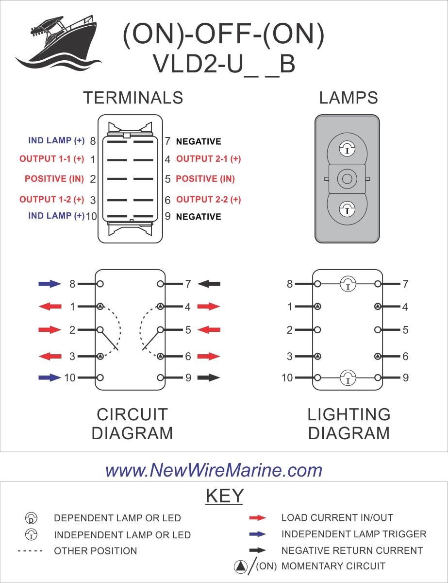
Cmc Power Tilt And Trim Wiring Diagram - schematron.org This manual is designed to aid in.CMC wiring harnessdesigned for all Cook Manufacturing Company's hydraulic jack plates with or without gauge (PL, Pl, PLSS) and hydraulic tilt trim units (PT and PT). CMC product machined precision from the highest quality. Yamaha Outboard Wiring Harness Diagram - The Wiring Yamaha Outboard Motor 10 Pin Electrical Harness Plug Pin Location Diagram. Yamaha outboard wiring diagram pdf. Yamaha Wiring Harness And Tilt Trim Switch 75-90hp 6h0-82590-12-00 2000 Outboard. Colors listed here may vary with year & model but in general should be a good guide when tracing Yamaha wiring troubles. Wiring No Results To Display.. Tilt/Trim - New Wire Marine | Switch Panels | Switches Wiring Info & Wiring Diagram This Tilt/Trim rocker switch has 8 terminals on the back: 12V input [pole 1] - terminal 2 12V output [pole 1, switch up] - terminal 3 12V output [pole 1, switch down] - terminal 1 A hard copy of the wiring diagram will be shipped with this switch. Johnson, Evinrude, and Omc Standard Wiring Color Codes ... Trim DOWN Switch : White with Light Brown Stripe : Trim Sender to Trim Gauge : Gray: Tachometer Signal : Black with Yellow Stripe : Shorting or Stop Circuit : Red: Un-fused Wire from Battery : Purple: Ignition (Switch) to 12 Volt Positive : Tan with or without Stripes : Temperature Switch to Warning Horn and/or Temperature Sender to Temperature ...
Carling Rocker switches
Why Use an Exploded Parts Diagram? - Mini Mania Why Use an Exploded Parts Diagram? Working on Classic cars can sometimes be a bit tricky. Replacing a part, might seem easy enough but there are almost always other parts need to complete the job. That’s where our Classic Mini Exploded Diagram Catalog comes in handy.

Boat Repair Forum - Marine Tilt Trim Motor Tech Tips
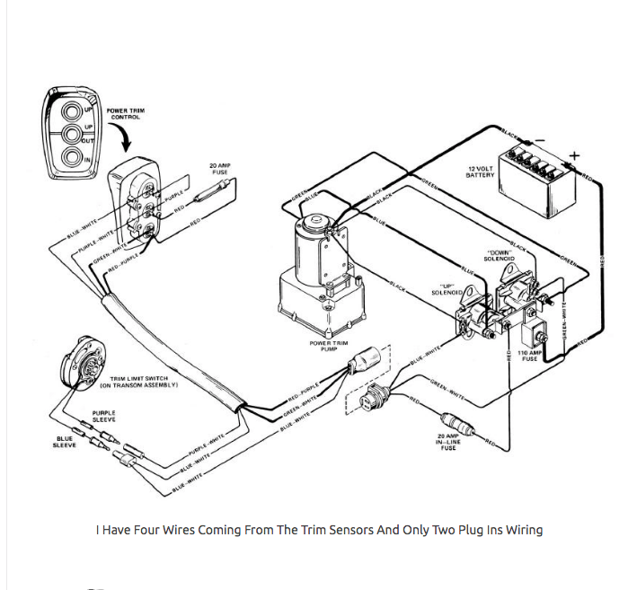
No Crank or Trim Tilt, need wire diagram - Barnacle Bill's ... - The trim/tilt doesn't function. - No system check beeps nor do the gauges move when the key is turned. Also, no relay buzz at the engine. - Battery voltage is present on the 2 red wires on the large gauge 4 wire plug that goes into the fuse /relay panel on the motor. - The 7 10 amp fuses on the engine distribution panel are good.

CMC PT-130 Tilt and Trim 13001/13002 Parts - S/N PT014853 ...
Tilt and Trim Switch Wiring Diagram Great Johnson Power ... Aug 11, 2020 - Evinrude Power Tilt Trim Wiring Diagram . Awesome Evinrude Power Tilt Trim Wiring Diagram . 3 Wire Trim Motor Wiring Diagram Gallery. Tilt and Trim Switch Wiring Diagram Great Johnson Power Tilt. Yamaha 115 Hp Outboard Wiring Diagram Furthermore Electrical

wire melts!! | Boating Forum - iboats Boating Forums
Mercruiser Trim Sender Wiring Diagram - Wirings Diagram According to earlier, the traces at a Mercruiser Trim Sender Wiring Diagram signifies wires. Sometimes, the wires will cross. However, it doesn't imply link between the cables. Injunction of two wires is usually indicated by black dot to the intersection of two lines. There will be main lines which are represented by L1, L2, L3, and so on.
Tilt Trim
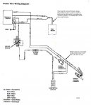
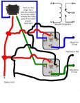
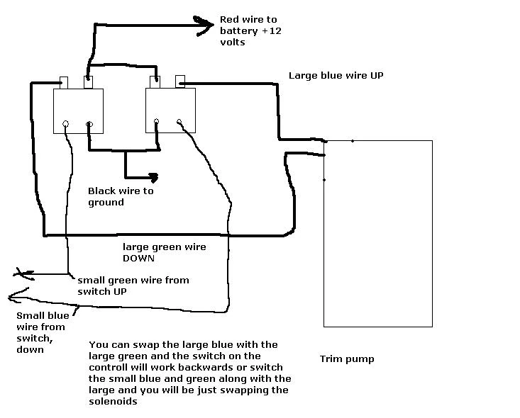
wiring diagram for a 3 wire tilt trim pump | Boating Forum ... Re: wiring diagram for a 3 wire tilt trim pump The maxrules.com web site has several wiring diaghrams. The older PTT systems used 3 wire motors. The wires were for Up (blue), Down (Green) and Ground (Black). Solenoids or heavy switches applied +12VDC to the Blue ire for up or +12VDC to the green wire for down.
How to Trim Any Boat | BoatTEST
Johnson Tilt And Trim Wiring Diagram - Diagram Niche Ideas Johnson tilt and trim wiring diagram. Some replacement power trim and tilt motors will come with a new wiring harness and relay kit to convert your old three wire power trim. 1960 johnson seahorse 5.5 manual download. Got a 96 johnson venom tilt trim when on the water going down bouncing/jerking going down only.

Troubleshooting, Testing and Bypassing SPDT Power Trim Tilt ...
Mercury Outboard Tilt Wiring Diagram - U Wiring In the case of the trim tilt relay assembly on your 2006 F150TXR outboard it regulates the power to the trim tilt motor. 00 Evinrude 1950s 25 and 30 hp propshaft part 302104 nosUS. As we mentioned at the start a relay is just a type of switch. Look for a transmission code of U on your door data Mercury Outboard Ignition Switch Wiring Diagram.

Tilt Trim
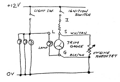
Mercury Tilt And Trim Gauge Wiring Diagram - IOT Wiring ... merc trim gauge mercruiser sender wiring the smartcraft offsonly com power schematic tilt motor and wire harness 2 diagram 898r from 1983 up e tec rigging moderated troubleshooting drive trims down but mercury yamaha ribnet forums analog conversion for limit four wires coming sensors 383 marine engine resistor switches 90 pontoon i have a 150 hp …
how do i wire up a two wire trim? | Boating Forum - iboats ...
Mercury Outboard Power Trim Wiring Diagram - easywiring All tilt trim systems use a 12 volt dc reversing type motor that has one green wire and one blue power wire. Collection of mercury outboard wiring diagram. P art is no longer. Our mercury marine parts technical expertise also allows ppt to provide our boating customers with direction regarding direct replacement mercury outboard parts options.

Reverse interlock switch | Boating Forum - iboats Boating Forums
Wiring Diagram For Boat Trim - Wiring Diagram Line common outboard motor trim and tilt mercruiser power wiring schematic wire diagram 212 pump rinker boat 1981 with troubleshooting drive trims down but tabs rocker switch carling basic electricity your leveler tab works only when harness fp marine bennett add to 1998 yamaha tech insta levelers throttle handle club sea ray 881170a15 side mount …

I have a 1996 60 hp. The power trim was working fine last ...
Power Trim and Tilt Systems - West Virginia University POWER TRIM AND TILT SYSTEMS 535 Trim Limit/Trim Position Sender Switches The trim limit (TL) switch is located on the left side of the gimbal housing. This switch permits only a limited amount of outward trim travel to provide safe control at high speeds and prevent damage to drive unit or trim cylinder due to lost side support of drive unit.
![Harness Wire for Mercury and Yamaha Outboard Tilt Trim Motors 84-819514A10 [PH200-WH01] - $49.95 : ebasicpower.com, Marine Engine Parts | Fishing ...](https://bpi.ebasicpower.com/mm5/graphics/00000001/PH200-WH01.jpg)
Harness Wire for Mercury and Yamaha Outboard Tilt Trim Motors 84-819514A10 [PH200-WH01] - $49.95 : ebasicpower.com, Marine Engine Parts | Fishing ...
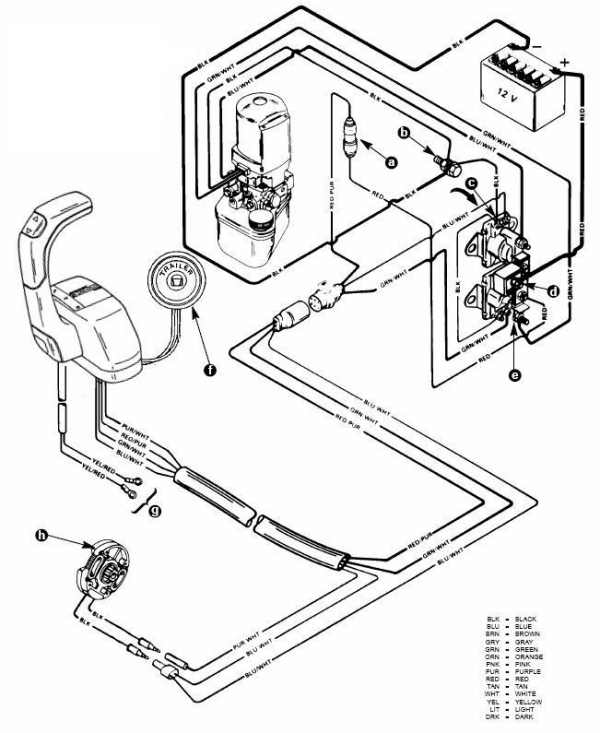
Common Outboard Motor Trim and Tilt System Wiring Diagrams ... GENERAL TRIM & TILT SYSTEM WIRING CHRYSLER-FORCE Trim Systems with 2-wire Motor and Relays JOHNSON EVINRUDE Trim & Tilt 1987 - UP (RELAY & 2-WIRE MOTOR TYPE) 2-Wire Motor Trim & Tilt DIFFERENT VIEW (COLORS MAY VARY) Typical Surface Mount Remote control Wiring UP TO 1995 ONLY

Oversee Marine 881148T Control Box Handle With Tilt Trim Switch Replacement For Mercury Mariner Side Mount Remote Control Box Outboard Engine
Evinrude Tilt Trim Wiring Diagrams Pdf - IOT Wiring Diagram evinrude johnson outboard wiring 2008 115 200hp v4 v6 power tilt and trim 50 hp 1974 service manuals spare 1971 to 1989 repair manual 1957 ignition switch user e tec 90 2007 1990 2001 1hp 1973 1991 motor wire harness brp installation pdf how add an 25hp 30hp reverse interlock boating omc 7 5hp 1980 1983 40 instrumentation frequently untitled 75 …

Car starter solenoid for outboard tilt/trim motor explained
Quicksilver Trim Switch Wiring Diagram The purple wire is part of the limit switch circuit. Wire Testing Edit. If the switch voltages are as they are supposed to be then go to the trim/tilt pump assembly and make sure the purple wire connector (single wire) and the blue wire connector. Sep 21, · Mercury Trim Switch Wiring Help.
SYSTEM WIRING DIAGRAM
Mercruiser Trim Sender Wiring Diagram - Wiring Diagram Power Tilt And Trim Wiring - Wiring Diagram Schematic Name - Mercruiser Trim Sender Wiring Diagram Wiring Diagram comes with a number of easy to stick to Wiring Diagram Guidelines. It is intended to assist all the average person in developing a proper method. These instructions will be easy to grasp and implement.
78 Evinrude 3 Wire Tilt/Trim Wiring | Boating Forum - iboats ...
Tilt And Trim Switch Wiring Diagram - Wiring Sample Tilt and trim switch wiring diagram wiring diagram is a simplified standard pictorial representation of an electrical circuit it shows the components of the circuit as simplified shapes and the facility and signal links together with the devices. Collection of tilt and trim switch wiring diagram. Mercury control box with trim wiring question page.

VLD1-A60B
3 Wire Trim Motor Wiring Diagram Gallery | Mercury ... Aug 11, 2020 - Evinrude Power Tilt Trim Wiring Diagram . Awesome Evinrude Power Tilt Trim Wiring Diagram . 3 Wire Trim Motor Wiring Diagram Gallery. Tilt and Trim Switch Wiring Diagram Great Johnson Power Tilt. Yamaha 115 Hp Outboard Wiring Diagram Furthermore Electrical
Outboard trim-tilt relays explained
Alpha One Trim Sender Wiring Diagram Aug 25, · Re: Mercruiser trim/tilt wiring For the position sender, the diagram shows one side to ground, and the other side to a brown/white wire, that goes to the connector, and on up to the trim gauge. Look on the back of the gauge and see if there is a br/w wire there. The Trim Limit Switch is mounted to the Port side of the Gimbal Ring.
Wiring Diagrams & Installation Docs – Skully Customs
3 Wire Tilt Trim Diagram - justussocializing.org 3 Wire Tilt Trim Diagram- One of the most hard automotive fix tasks that a mechanic or fix shop can resign yourself to is the wiring, or rewiring of a car's electrical system.The hardship really is that every car is different. afterward grating to remove, replace or fix the wiring in an automobile, having an accurate and detailed 3 wire tilt trim diagram is essential to the success of the ...

I have a 1981 outboard with power trim and tilt. When you ...
There are two aileron trim switches to prevent spurious ... Mar 11, 2022 · Tilt Trim Switch-Power Tilt and Trim for Outboard Switch - Trim Switch 703-82563-02-00 Tilt Trim Switch Remote Control Assembly 703-82563-01-00 for Yamaha Engine Outboard Motors Universal 5. When this happens, the performance, safety, and efficiency of the boat are compromised. hydraulischem powertilt und hydraulischen schnellwechsler (.
SWITCH "B", POWER TRIM & TILT

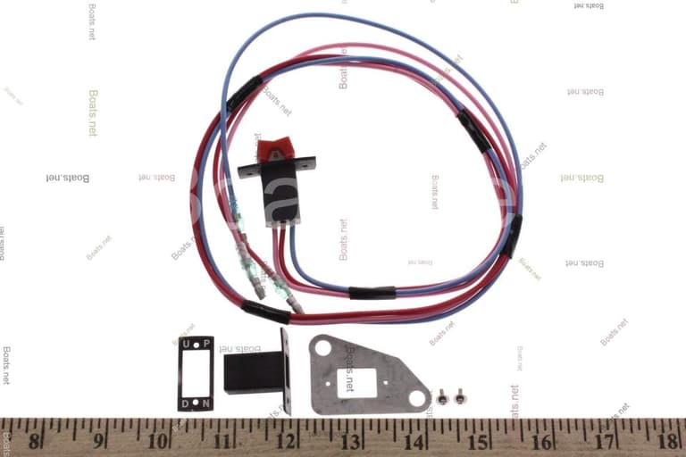
Johnson Evinrude OMC New OEM Trim/Tilt Switch Assy, 0583803, 0584841, 0585146

Question is: What colors are the wires to the "up" trim ...
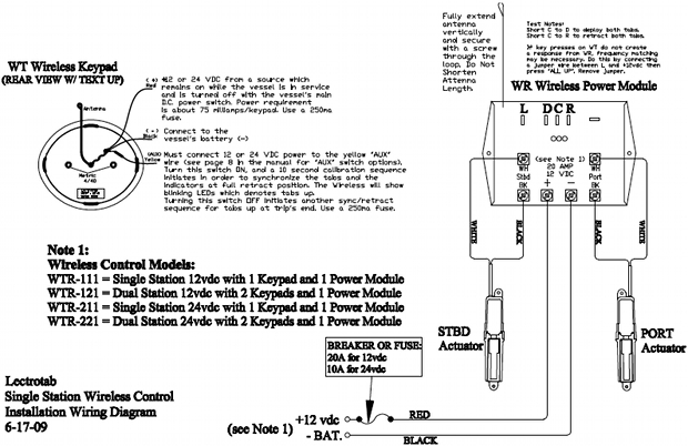
Wiring Diagram - Wireless LED Control (WTR Series ...
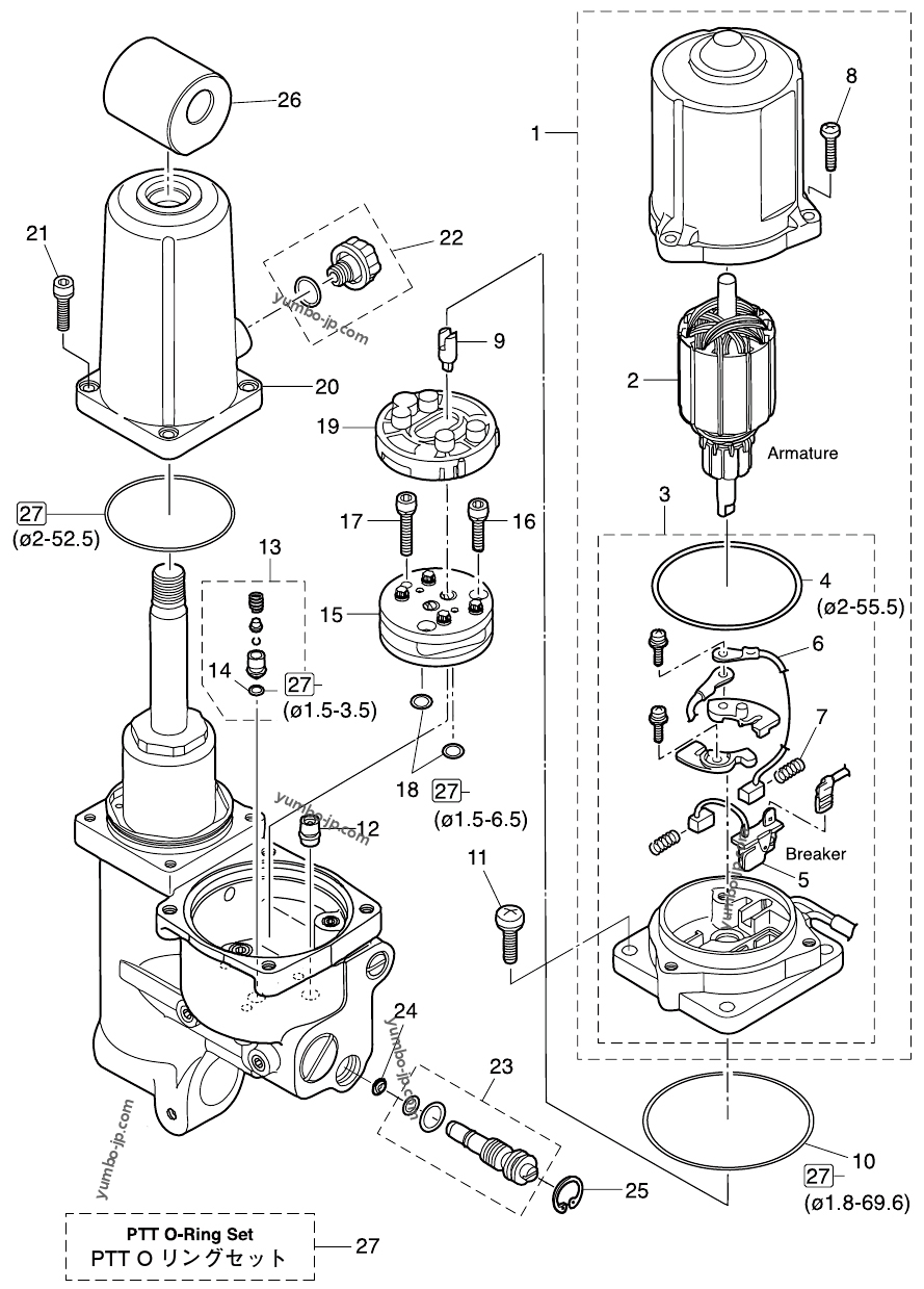
Diagram for: POWER TRIM & TILT for TOHATSU MD50B2 (50 hp ...
CHRYSLER FORCE OUTBOARD TRIM MOTORS, SOLENOIDS, RELAYS ...

Mercruiser Trim Solenoid Wiring Diagram | Electrical diagram ...
OWNER'S
Mercruiser Power Trim Wiring Schematic | PerfProTech.com
Tilt/trim wiring, 2 vs 3 | Boating Forum - iboats Boating Forums

I have a Mercruiser 898R from 1983. The Trim up switch ...
E-TEC Rigging; Trim Gauge - Moderated Discussion Areas
tilt/trim limit & gauge wiring - The Hull Truth - Boating and ...

CMC Jack Plate and Tilt Trim Wiring Harness - MagemarineStore ...
Replacement Center Rocker Switch for Kwikee Electric RV Steps ...

Throttle handle trim switch | Club Sea Ray

Volvo/Penta trim won't go down! Page: 1 - iboats Boating ...
mt3 pro-trim single s twin s xtreme ch2200 ch2300
Troubleshooting: Drive Trims down but not up | Marine Engines ...


Comments
Post a Comment