40 wireless charger circuit diagram pdf
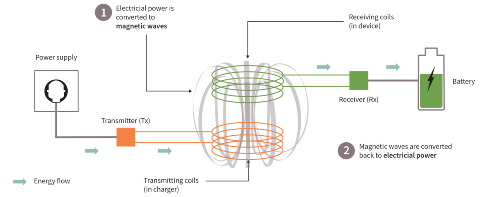
PDF Wireless Battery Charging-PBattezzato - STMicroelectronics • Tightly coupled wireless charging technology uses magnetic induction to transfer power from a transmitter (Tx) to a receiver (Rx). • The magnetic field is generated by a coil on the TX side. The field is captured by a coil on the RX side. The field works through air, no magnetic circuit links the coils. Wireless Mobile Battery Charger : Circuit, Kits, Theory The Wireless Mobile Battery Charger System uses one coil with small circuit inside the mobile phones launched after October 2012 and the external charger unit. Ready to use Wireless Mobile Battery Charger units are definitely available. They have two parts.
manuals.plus › willful › m98-bluetooth-wirelesswillful M98 Bluetooth Wireless Headset User Manual Oct 09, 2021 · willful M98 Bluetooth Wireless Headset User Manual Contents hide 1 Product Specification 2 Product Overview 3 Basic Operation 4 Bluetooth Pairing and Connection 4.1 Multi Point Connection 5 Charging 6 LED Indicator 7 Attention and Q & A 8 Packaging Contents: 9 Documents / Resources 9.1 Related Manuals / Resources Product Specification Item No. M98 … Continue reading "willful M98 Bluetooth ...

Wireless charger circuit diagram pdf
› publication › 290192630(PDF) Wireless Power Transfer - ResearchGate Download full-text PDF Read full-text. Download full-text PDF. ... Circuit Diagram . 9 . ... The purpose of this research is to produce wireless power charger system used for ... Wireless Mobile Charger Circuit Diagram - Engineering Projects Math's involves in Wireless Mobile Charger Circuit Diagram The entire calculation shown below is done by considering the parts list value in this circuit. Transmitter Circuit: - As the 555 is wired in an astable multivibrator thus we have to calculate pulse oscillation. Charging time = Discharging time = Oscillating Frequency of 555 = PDF Wireless Mobile Charger Circuit using Inductive Coupling Wireless power transmission mobile charger circuit using inductive coupling is to charge a low power device using wireless power transmission. This is done using charging a resonant coil from AC and then transmitting subsequent power to the resistive load. The project is meant to charge a low power device quickly and efficiently by
Wireless charger circuit diagram pdf. PDF An Overview of Resonant Circuits for Wireless Power Transfer The purpose of this paper is to give an overview of resonant circuits for the near-field WPT system. The state-of-the-art technology of these resonant circuits, including the non-resonant converters with a resonant tank and resonant inverters, will be reviewed and discussed. PDF Wireless Inductive Charging for Low Power Devices - Theseus A variety of wireless power technologies have been explored recently over different power levels as shown in figure 1 below Figure 1 Overview of current wireless power technologies (Reprinted from Tianjia Sun (2013) [5] A lot of medical implants rely on wireless power to function. Cochlear ear implant is a good example of such a device. Build Your Own Induction Charger | Nuts & Volts Magazine Connect the coils to your breadboard circuits and attach the meters as shown back in Figure 1. Place the receiver coil over the transmitter coil, separating them with one of the acrylic blocks to act as an insulator. Apply power to the transmitter circuit and record the values from both meters. circuit-diagramz.com › circuit-diagram-smps-powerSmps Circuit Diagram Power Supply May 02, 2016 · Circuit Diagram Of Smps Power Supply Like other power supplies, switch-mode power supply is a complicated circuit that supplies the power from a source to loads. Switch-mode power supply is necessary for power consuming electrical & electronic appliances & even for preparing electrical & electronic projects.
PDF Wireless Charging of Electric Vehicles reliability of the charging of electric vehicles. Wireless power charging is done by inductive coupling. Inductive coupling can done in both stationary and dynamic conditions. By reconfiguring the transformer and altering high frequency, energy is being transferred with low energy loss and fewer demands on the primary circuit. PDF 400mA Wireless Power Receiver & Buck Battery Charger The LTC®4120, a high performance wireless receiver and battery charger, serves as the central component of the receiver electronics in a wireless battery charging system. The Linear Technology wireless power system is designed to transmit up to 2W to a battery with a maximum charge current of 400mA. PDF Wireless Mobile Charger Circuit Diagram Wireless Mobile Charger Circuit Diagram Author: traderegistration.ditp.go.th-2022-03-20-08-51-43 Subject: Wireless Mobile Charger Circuit Diagram Keywords: wireless,mobile,charger,circuit,diagram Created Date: 3/20/2022 8:51:43 AM PDF Battery Charging - Texas Instruments Figure 1 shows a schematic diagram of a circuit which will fast-charge a 12V Ni-Cd or Ni-MH battery at 2.6A and trickle charge it when the converter is shut off. Note that the circuit must have a shutdown pin so that the end-of-charge detection cir-cuit(s) can terminate the fast charge cycle when the battery is full (the LM2576 has a
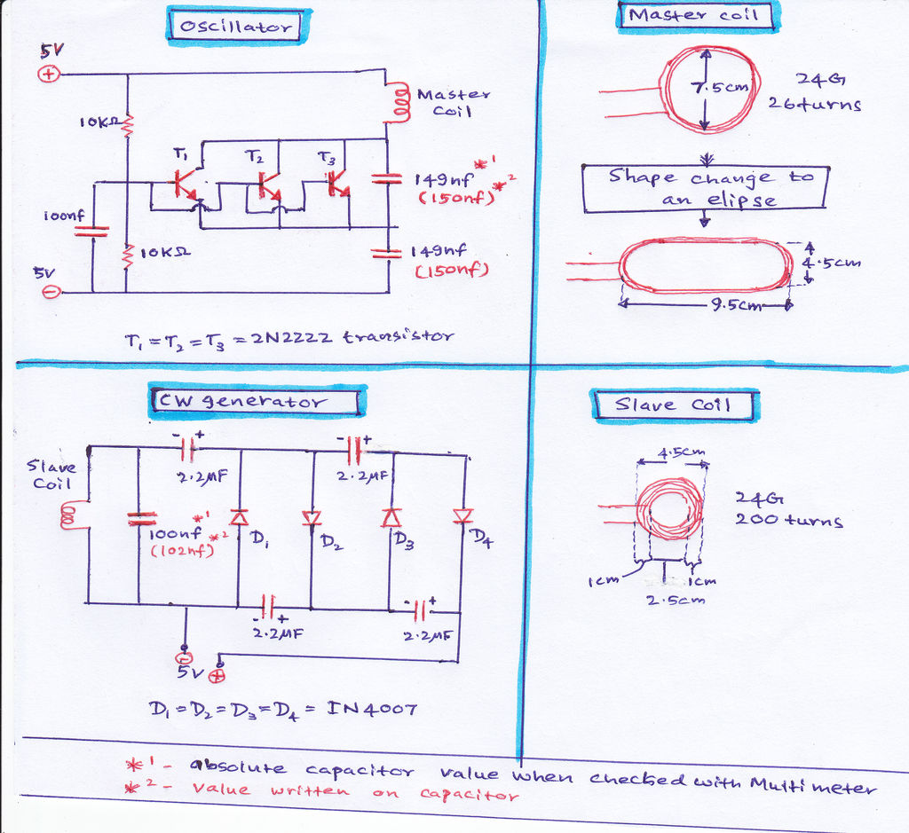
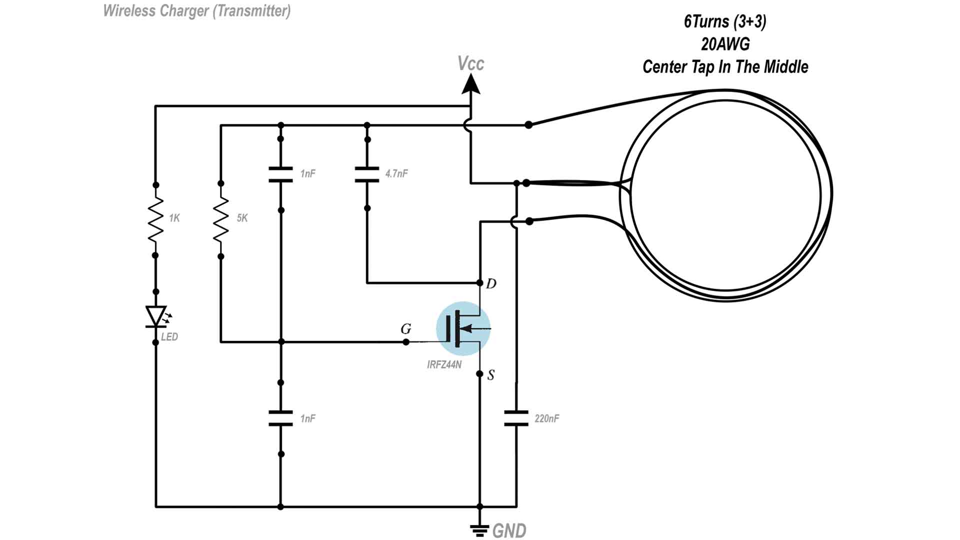
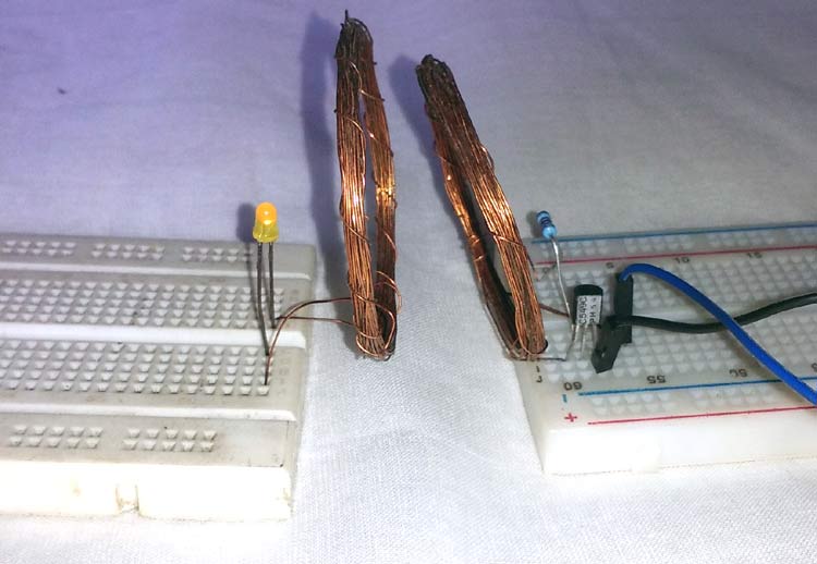
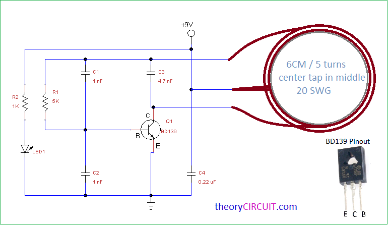
› publication › 275208316(PDF) 270 MINI ELECTRONICS PROJECT WITH CIRCUIT DIAGRAM Apr 20, 2015 · PDF | This Book is written for all the people who love innovation. ... circuit diagram help from this book. Give your feedback by mailing me. ... Battery Charger with Automatic Switch-off 71. 119 ... Wireless Gadgets Charger Circuit - theoryCIRCUIT Voltage/Current regulation circuit limits energy and applies to the target device. Wireless Gadgets Charger Circuit Transmitter Circuit Construction and Working This circuit constructed to produce high frequency magnetic flux. The center tapped Coil is made through 20 SWG Enameled copper wire 6 CM dia and 5 turns with center tap in middle. PDF Intelligent Dynamic Wireless Charging System for Electric ... dynamic wireless charging based on the IOVis constructed, which includes mobile phone client and network server. Google map is used to realize the functions, such as location, charging road display, path planning, navigation, start or finish charging request, payment. MySQL databaseis utilized to save the information of charging road PDF Designing Wireless Charger Circuit for Hearing Aids Using ... General diagram block of suggested design of wireless charge r- Ci cuit for hearing aid. Figure 2. Spiral antenna [6]. Figure 3. Spiral antenna and its design parameters [7] . To design a suitable impedance matching for the suggested model, following equations are essential, Circuit which will be discussed.
How to make mobile charger easy at home
Wireless Power for Mobile Battery Charger - IAES Core Figure 1. Block Diagram of Wireless Power Transfer This Wireless Mobile Battery Charger project need several circuit such as oscillator circuit (transmitter), charging circuit (receiver), and a couple of coils (act like an antenna), a power supply (input) and output from phone battery (low power device) [11]. The basic block

Circuit Diagram for the Portable Solar Mobile Charger ...
Wireless Mobile Charger Circuit Diagram Pdf - U Wiring Wireless mobile charger circuit diagram pdf. 2 Block Diagram of Wireless Charger The block diagram of wireless charger consists of Ac power supplier rectifier LC oscillator circuit transmitter receiver and current amplifier which is shown in fig. Most wireless chargers use magnetic induction and magnetic resonance.
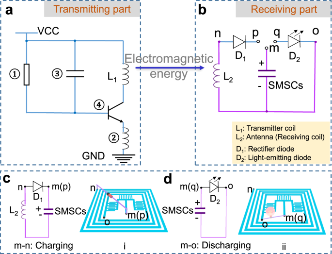
A seamlessly integrated device of micro-supercapacitor and ...
(DOC) Wireless Mobile Battery Charger Circuit Wireless ... note: also get an idea about the battery level indicator project circuit and its working how to operate this wireless power transfer circuit? initially, connect the circuit as shown in the circuit diagram. switch on the supply. connect the battery charger at the output of the circuit. place the receiver coil near the transmitter coil . you …

Wireless Mobile Charger Circuit Diagram - Engineering Projects
PDF Wireless Inductive Charging - University of Utah College ... circuit in this project will be based on the guide "Wireless Power Charger!" [10] found on Instructables.com. The schematic for the primary circuit can be found in Figure 4. The secondary circuit diagram can be found in Figure 5. In addition to the schematic, the primary circuit will also have a

USB Mobile Charger Circuit PDF | PDF | Battery Charger | Usb
Circuit Diagram | Portable Qi Charger | Adafruit Learning ... Take a moment to review the components in the circuit diagram. This illustration is meant for referencing wired connections - The length of wire, position and size of components are not exact. A Micro-B USB connects to 5V and G on the PowerBoost1000C via 50mm long wires. The Micro-B USB connects to the Micro USB port on the Qi board.
International Journal of Soft Computing and Engineering
PDF Recent Advances in Circuits Wireless Power Transfer ... The schematic diagram of WPT system is illustrated in Fig.1. Fig. 1 Schematic diagram of WPT system The high speed switching circuit is a single-ended high frequency quasi resonant inverter that consists of power MOSFETs and triggering circuits. A power MOSFET is a Metal Oxide Semiconductor Field Effect Transistor ( MOSFET

Wireless Mobile Charger Circuit Diagram - Engineering Projects
› high-voltage-highHigh Voltage, High Current DC Regulator Circuit - Homemade ... Jan 24, 2022 · Referring to the circuit diagram, the IC 741 becomes the heart of the entire regulator circuit. Basically it has been set up as a comparator. Pin#2 is provided with t a fixed reference voltage, decided by the value of the zener diode.

USB Cellphone Charger circuit
PDF L1 Design And Construction Of Wireless Charging System ... 12V Battery Oscillator Circuit (1. 67 MHz) Transmitter Coil Receiver Coil DC Level Stabilizer Charging Battery Fig. 1. Block diagram of wireless power transfer system In this project, supply voltage 12 DC drives oscillator circuit as push-pull driver to operate transmitter coil.
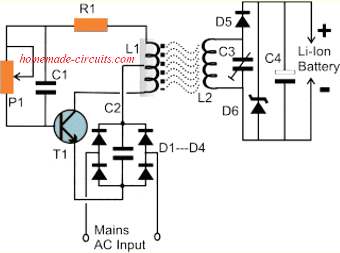
Wireless Li-Ion Battery Charger Circuit - Homemade Circuit ...
Cell Phone Charger Circuit Diagram Mobile phones generally charge with 5v regulated DC supply, so basically we are going to build a circuit diagram for 5v regulated DC supply from 220 AC. This DC supply can be used to charge mobiles as well as the power source for digital circuits, breadboard circuits, ICs, microcontrollers etc.

Automatic Battery Charger Circuit projects - ElecCircuit.com
PDF Circuits and Systems for Efficient Portable-to-Portable ... A custom integrated circuit designed in 0.18 µm HVCMOS implements the derived control loop by sensing for power amplifier zero-voltage switching and adjusting the power amplifier components. An end-to-end efficiency of 78% is achieved when delivering 200 mW over a 7 mm distance. Efficiencies over 70% are maintained over 4-12 mm distances.
Wireless Cellphone Charger Circuit - Homemade Circuit Projects
› SchematicsElectronic Circuit Schematics USB charger circuit diagram: Power: Aug 18, 2009 ... FROGSND Arcade game circuit diagram (PDF) Games: Mar 30, 2014 ... devices for wireless distance and position ...

Wireless Mobile Charger Circuit Diagram - Engineering Projects
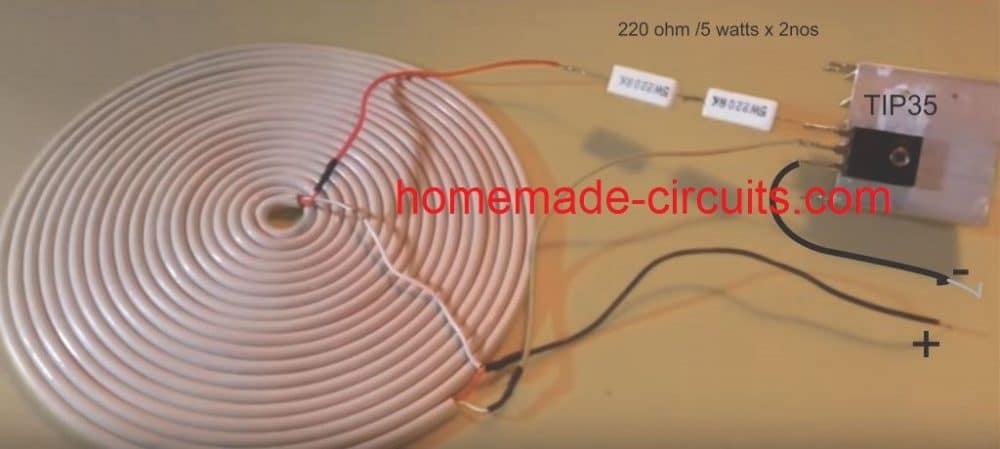
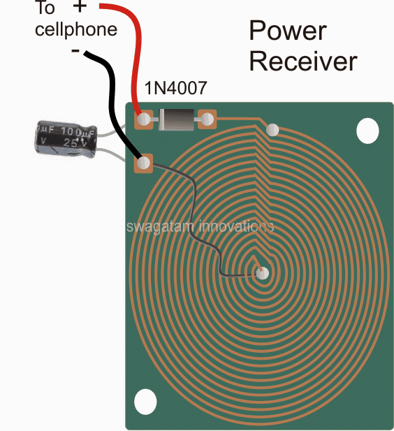
Wireless Cellphone Charger Circuit - Homemade Circuit Projects The transmitter circuit for this wireless cellphone charger is the crucial stage and must be built accurately, and it must be structured as per the popular Tesla's pancake coil arrangement as shown below: DIAMETER OF THE COIL IS AROUND 18 CMS Making a PCB version of the above Pancake coil.
Wireless Cellphone Charger Circuit - Homemade Circuit Projects
PDF EE 198B Final Report "WIRELESS BATTERY CHARGER" (RF ... rectifier circuit in the receiver will convert the RF/ microwave signal into DC signal. After the DC signal is produced, the charging circuit will store the power into the battery. Here is the block diagram of the overall design. Figure 1: The overall wireless battery charger design 4
Results page 180, about 'IR Receiver'. Searching circuits at ...
(PDF) Wireless Mobile Charger - Academia.edu WORKING PRINCIPLE AND HARDWARE DESCRIPTION 3.1 Working Principle Fig. 2 Block Diagram of Wireless Charger The block diagram of wireless charger consists of Ac power supplier, rectifier, LC oscillator circuit, transmitter, receiver and current amplifier, which is shown in fig. 2.
Lead Acid Battery Charger Circuit
DIY Wireless Charger : 7 Steps (with Pictures) - Instructables Step 4: The Oscillator Circuit... 3 More Images There are lots of way of making an oscillator circuit . In this circuit we will use a 555 timer IC to produce a signal of 143.75 Khz but its not enough to drive the LC circuit (transmitter coil with capacitor in series). so we have to build a H bridge mosfet driver circuit to drive the LC circuit.
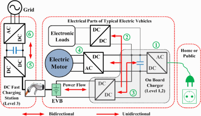
Electric Vehicles Charging Technology Review and Optimal Size ...
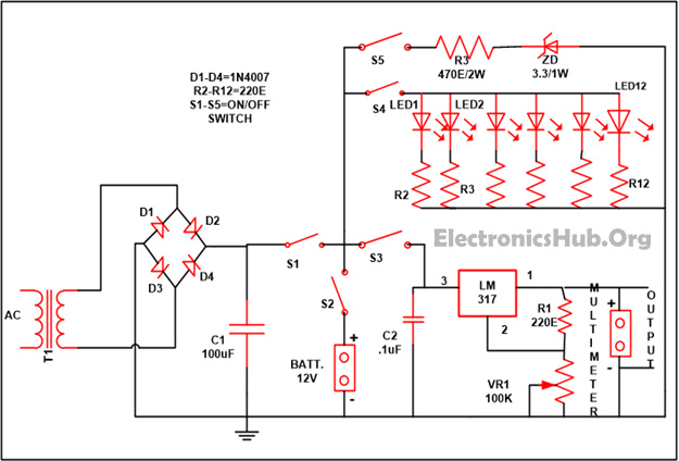
PDF USB Mobile Charger Circuit - idc-online.com Circuit Diagram of USB Mobile Charger: USB Mobile Charger Circuit Diagram - ElectronicsHub.Org Components used in this Circuit: R1-470E C1-100uF/25V T1-BC547 Zener diode-4.7V/. 5W Diode-1N4007 Components Description: Resistor: Flow of current in the circuit is being controlled by the resistor.
Homemade wireless smartphone 5V charger DIY circuit
PDF Wireless Mobile Charger Circuit using Inductive Coupling Wireless power transmission mobile charger circuit using inductive coupling is to charge a low power device using wireless power transmission. This is done using charging a resonant coil from AC and then transmitting subsequent power to the resistive load. The project is meant to charge a low power device quickly and efficiently by

Contacting an Applications Engineer - Support - Engineering ...
Wireless Mobile Charger Circuit Diagram - Engineering Projects Math's involves in Wireless Mobile Charger Circuit Diagram The entire calculation shown below is done by considering the parts list value in this circuit. Transmitter Circuit: - As the 555 is wired in an astable multivibrator thus we have to calculate pulse oscillation. Charging time = Discharging time = Oscillating Frequency of 555 =
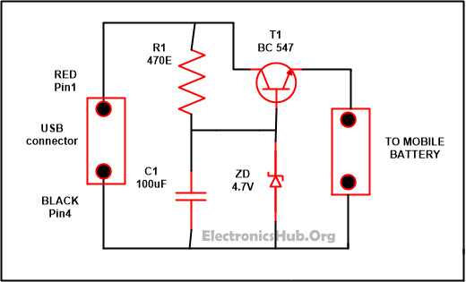
USB Mobile Charger Circuit | Mobile Phone Travel Charger
› publication › 290192630(PDF) Wireless Power Transfer - ResearchGate Download full-text PDF Read full-text. Download full-text PDF. ... Circuit Diagram . 9 . ... The purpose of this research is to produce wireless power charger system used for ...

Wireless Power Transmission Project using 555 Timer IC ...
Circuit Diagram Software
Wireless charging – power transfer - Infineon Technologies
HT4928S Ver1.1 1/6

Wireless Power Transmission Mobile Charger Circuit Using ...
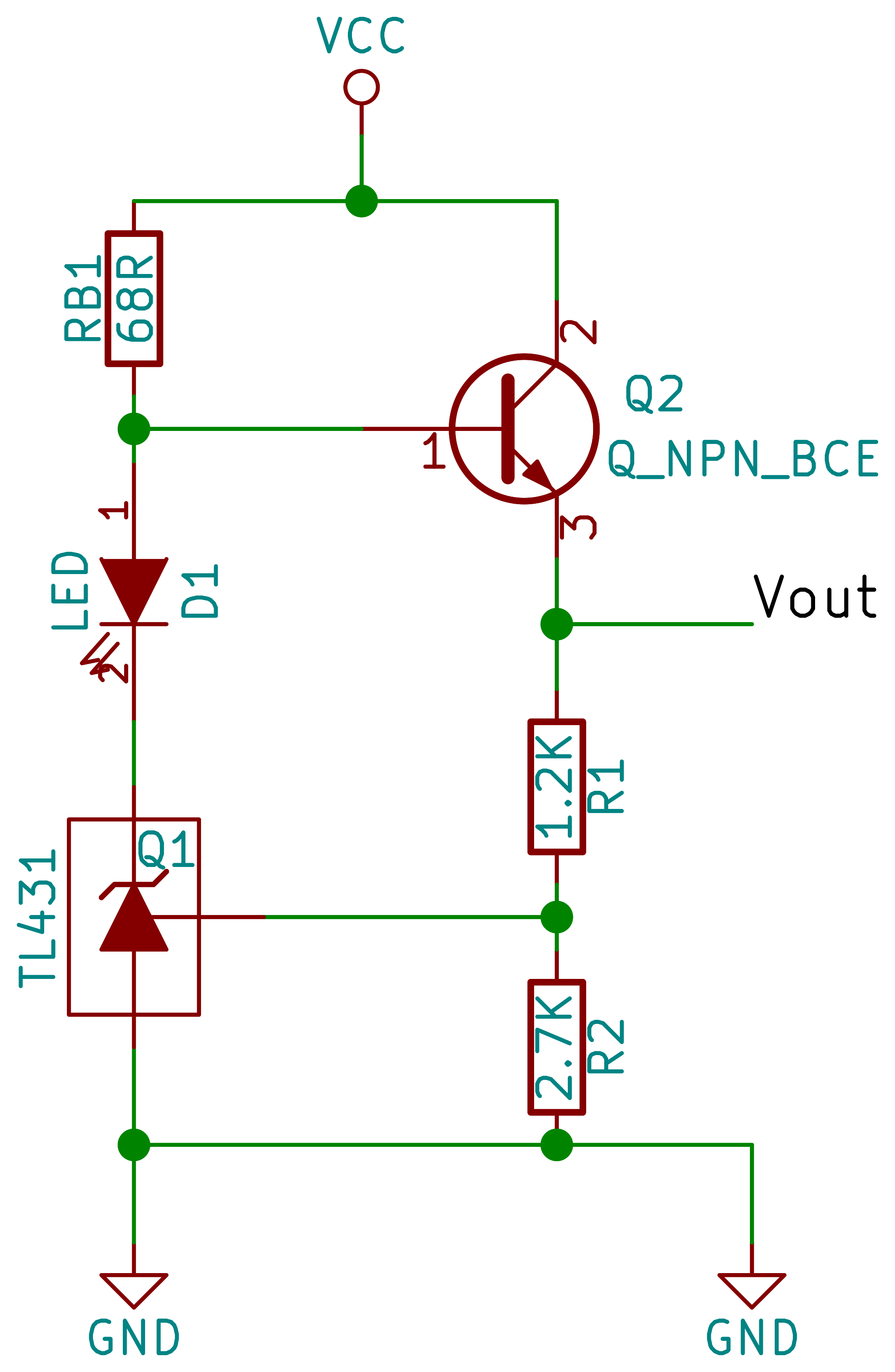
Ode To The TL431, And A LiFePO4 Battery Charger | Hackaday
Simple Wireless Power Transmission Circuit to Glow an LED
Low wireless power transfer using Inductive Coupling for ...
Wireless Gadgets Charger Circuit
Wireless Mobile Charging Project

Wireless Power Transfer Project using 555 Timer
Mobile Phone Travel Battery Charger with Emergency Light
Wireless Battery Charging
Battery Charger Circuit | Full DIY Electronics Project
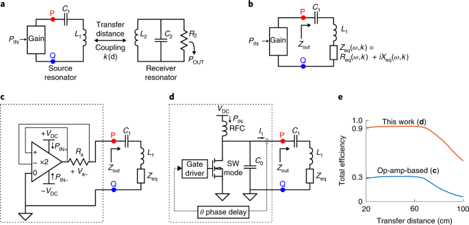
Robust and efficient wireless power transfer using a switch ...

DIY - Wireless Charger : 10 Steps (with Pictures) - Instructables

Wireless Mobile Charger : 5 Steps - Instructables

Mobile Phone Travel Charger

High-Range Wireless Power : 9 Steps (with Pictures ...

Wireless Charger Design Principle Concept Explained ...
Energies | Free Full-Text | Sustainable E-Bike Charging ...


Comments
Post a Comment