41 crystal oscillator circuit diagram
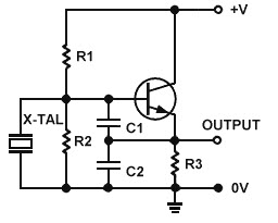
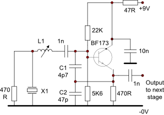
Quartz Crystal Oscillators - Electronics Tutorials The circuit diagram above of the Colpitts Crystal Oscillator circuit shows that capacitors, C1 and C2 shunt the output of the transistor which reduces the ... CRYSTAL OSCILLATOR CIRCUITS CRYSTAL OSCILLATOR CIRCUITS An oscillator circuit requires that two conditions be satis-fied: that it contains an amplifier having sufficient gain to overcome the loss due to its feedback network, and that the phase shift around the whole loop is zero at the wanted fre-quency. It must be ensured also that the loop gain at other
Hacker's Bench : Crystal Controlled 1Hz Time Base (Clock) In principal this circuit is extremely simple. You build a crystal oscillator, and then you divide its output down to 1Hz. The crystal we're going to use here run at 32.768 KHz ( 32768 Hz ). These are commonly called clock, or watch crystals. The significance of the value is that you can successively divide 32768 by 2 and eventually you will ...

Crystal oscillator circuit diagram
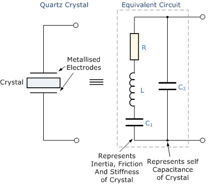
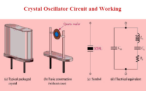
Electronic oscillator - Wikipedia In a crystal oscillator circuit the filter is a piezoelectric crystal (commonly a quartz crystal). The crystal mechanically vibrates as a resonator, and its frequency of vibration determines the oscillation frequency.Crystals have a very high Q-factor and also better temperature stability than tuned circuits, so crystal oscillators have much better frequency stability than LC or RC … DIY AM Transmitter-Circuit Diagram, Components, Description 27.11.2018 · The circuit has two parts, an audio amplifier and a radio frequency oscillator. The oscillator is built around Q1 (BC109) and related components. The tank circuit with inductance L1 and capacitance VC1 is tunable in the range of 500kHz to 1600KHz. These components can be easily obtained from your old medium wave radio. Overview of Crystal Oscillator Circuit Working with ... Crystal Oscillator Circuit Diagram. The above figure is a 20psc New 16MHz Quartz Crystal Oscillator and it is one kind of crystal oscillators, that works with 16MHz frequency. Crystal Oscillator. Generally, bipolar transistors or FETs are used in the construction of Crystal oscillator circuits.
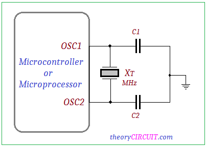
Crystal oscillator circuit diagram. Interfacing 16x2 LCD with 8051 microcontroller. LCD module ... 22.5.2017 · The circuit diagram given above shows how to interface a 16×2 LCD module with AT89S1 microcontroller. Capacitor C3, resistor R3 and push button switch S1 forms the reset circuitry. Ceramic capacitors C1,C2 and crystal X1 is related to the clock circuitry which produces the system clock frequency. Crystal Oscillator - Electronic Circuits and Diagrams ... Mar 28, 2011 · Crystal Oscillator. In crystal oscillators, the usual electrical resonant circuit is replaced by a mechanically vibrating crystal. The crystal (usually quartz) has a high degree of stability in holding constant at whatever frequency the crystal is originally cut to operate. The crystal oscillators are, therefore, used whenever great ... Crystal Oscillator Circuit Diagram (Ten Kinds of Crystal ... Mar 05, 2019 · Ⅲ Crystal Oscillator Circuit Diagram (3) The circuit oscillates in the frequency range from 100kHz to 5MHz. The operating characteristics are determined by the source resistance. The frequency can be adjusted using a trimmer capacitor. The output resistance is high, followed by a source follower as an isolator to support this shortcoming. Frequency Counter : Block Diagram, Circuit, Types and Its ... Frequency Counter Block Diagram Input. When the input signal with high input impedance and low output impedance is applied to this counter, then it will be fed to the amplifier to convert the signal into a square wave or rectangular wave for processing within the digital circuit.
TCXO (Temperature compensated crystal oscillator ... A TCXO (Temperature compensated crystal oscillator) is a crystal oscillator with a temperature-sensitive reactance circuit in its oscillation loop to compensate the frequency-temperature characteristics inherent to the crystal unit. Epson's are classified into two types. Crystal Oscillator: Circuit, Frequency & Working Principle Apr 16, 2021 — Crystal oscillators operate on the principle of inverse piezoelectric effect in which an alternating voltage applied across the crystal ... Crystal Oscillators - Tutorialspoint The following circuit diagram shows the arrangement of a transistor pierce crystal oscillator. In this circuit, the crystal is connected as a series element in the feedback path from collector to the base. The resistors R 1, R 2 and R E provide a voltage-divider stabilized d.c. bias circuit. Crystal Oscillator | Product | Epson crystal device This is a crystal oscillator that houses a SAW resonator chip and IC chip including crystal oscillation circuit in a package. Epson offers SAW oscillators under the EG series. In particular, the EG-2121 and EG-2102 have improved frequency-temperature characteristics to one-half their previous levels.
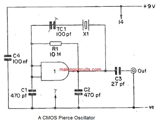
Crystal Oscillator Circuit: How to Build One Crystal Oscillator Diagram Source: Wikimedia Commons In simpler terms, a crystal oscillator circuit is the electronic circuit board that houses the device that produces a specific frequency. It’s also an electronic oscillator circuit that works with a vibrating crystal’s mechanical resonance—to generate a consistent frequency. Crystal oscillator - Wikipedia Circuit notations and abbreviations — The crystal oscillator circuit sustains oscillation by taking a voltage signal from the quartz resonator, amplifying ... 5 Crystal oscillator Circuits using CMOS - ElecCircuit.com Nov 17, 2018 · You want a crystal oscillator circuit, right? There are a lot of circuits diagram you do. How much frequency and waveform do you want? This is a simple Crystal oscillator circuit using 74LS04. It provides a square wave of 1MHz to 10MHz. Using an inverter gate IC and controls output frequencies with crystal. I will show you 5 circuits ideas below. Digital Temperature Controller | Full Circuit Diagram With ... 22.4.2016 · It includes 8kB Flash memory, 256-byte EEPROM, 368-byte RAM, 33 input/output (I/O) pins, 10-bit 8-channel analogue-to-digital converter (ADC), three timers, watchdog timer with its own on-chip crystal oscillator for reliable operation, and synchronous I2C interface. Fig. 2: Circuit diagram of the digital temperature controller
Crystal Oscillator - an overview | ScienceDirect Topics
Understanding Crystal Oscillator Circuits Mar 26, 2021 · Crystal Circuits The first circuit below is an emitter-coupled oscillator, a variation of the Butler circuit. The output of the circuit in Fig. 1 is basically sine wave; decreasing the emitter resistor of Q2 boosts the harmonic output. As a result, a 100 kHz crystal generates excellent harmonics via 30 MHz. It is a series mode circuit.
Transistor Crystal Oscillator Circuit » Electronics Notes
Crystal - Wikipedia A crystal or crystalline solid is a solid material whose constituents (such as atoms, molecules, or ions) are arranged in a highly ordered microscopic structure, forming a crystal lattice that extends in all directions. In addition, macroscopic single crystals are usually identifiable by their geometrical shape, consisting of flat faces with specific, characteristic orientations.
Simple Oscillator Circuits
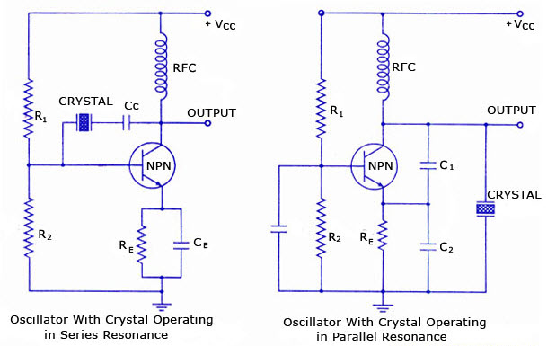
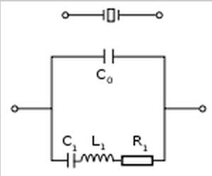
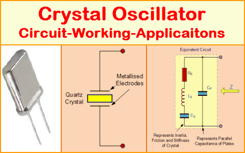
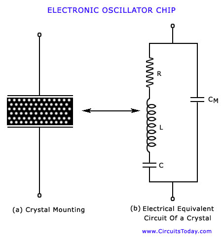
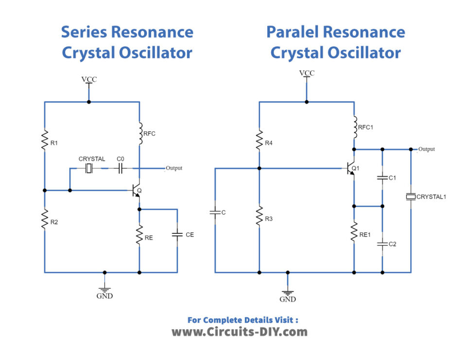
Crystal Oscillator : Working and Its Various Applications Sep 26, 2019 — The quartz crystal oscillator circuit diagram consists of series resonance and parallel resonance, i.e., two resonant frequencies. If the ...
How to Build Crystal Oscillator Circuits - Circuit Basics
CRYSTAL OSCILLATOR CIRCUITS - bgaudioclub.org 3.4. Crystal Response to a Step Input13 4. CIRCUIT DESIGN CHARACTERISTICS 4.1. Crystal’s Internal Series ResistanceR, 17 4.2. Load Impedance across the Crystal Terminals 18 4.3. Oscillator Loop Gain 19 4.4. Reduced Crystal Voltage Limits above 1 MHz 20 4.5. DC Biasing of Transistor and IC Amplifier Stages 21 4.6. Transistor High-Frequency ...
Overview of Crystal Oscillator Circuit Working with applications
Overview of Crystal Oscillator Circuit Working with ... Crystal Oscillator Circuit Diagram. The above figure is a 20psc New 16MHz Quartz Crystal Oscillator and it is one kind of crystal oscillators, that works with 16MHz frequency. Crystal Oscillator. Generally, bipolar transistors or FETs are used in the construction of Crystal oscillator circuits.
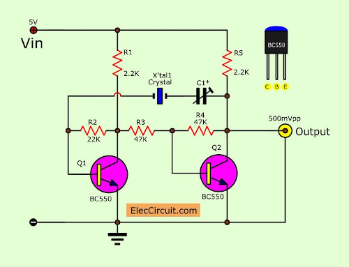
Transistor Crystal Oscillator circuit ideas | ElecCircuit.com
DIY AM Transmitter-Circuit Diagram, Components, Description 27.11.2018 · The circuit has two parts, an audio amplifier and a radio frequency oscillator. The oscillator is built around Q1 (BC109) and related components. The tank circuit with inductance L1 and capacitance VC1 is tunable in the range of 500kHz to 1600KHz. These components can be easily obtained from your old medium wave radio.

Transistor Crystal Oscillator circuit ideas | ElecCircuit.com ...
Electronic oscillator - Wikipedia In a crystal oscillator circuit the filter is a piezoelectric crystal (commonly a quartz crystal). The crystal mechanically vibrates as a resonator, and its frequency of vibration determines the oscillation frequency.Crystals have a very high Q-factor and also better temperature stability than tuned circuits, so crystal oscillators have much better frequency stability than LC or RC …
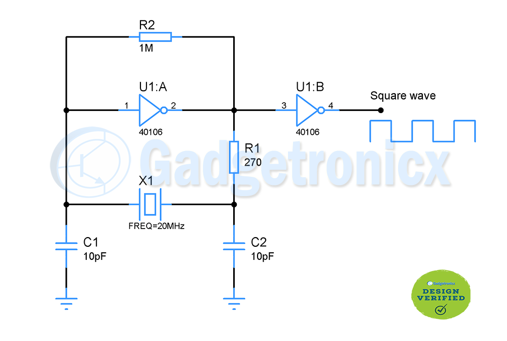
Square wave generator using Crystal oscillator - Gadgetronicx
Basics of quartz crystal oscillators

Electronic oscillator - Wikipedia
Crystal Oscillators: Simple, Low-Cost and Highly Accurate ...

A Low-Frequency Crystal Controlled Oscillator

Understanding Crystal Oscillator Circuits - Homemade Circuit ...
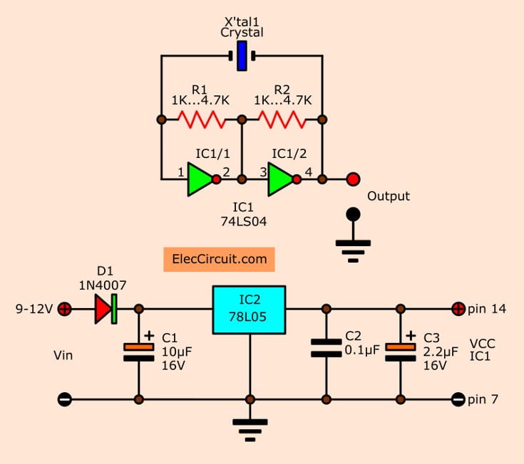
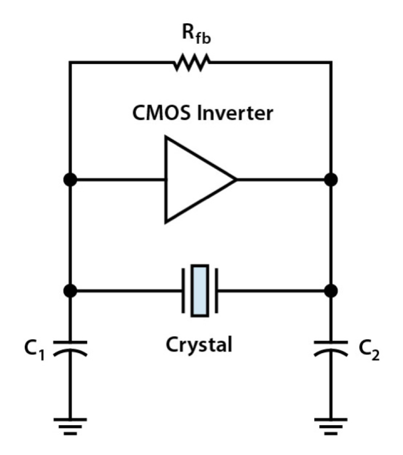
5 Crystal oscillator Circuits using CMOS | ElecCircuit.com
Overview of Crystal Oscillator Circuit Working with applications
Schematic diagram of a typical crystal oscillator circuit ...
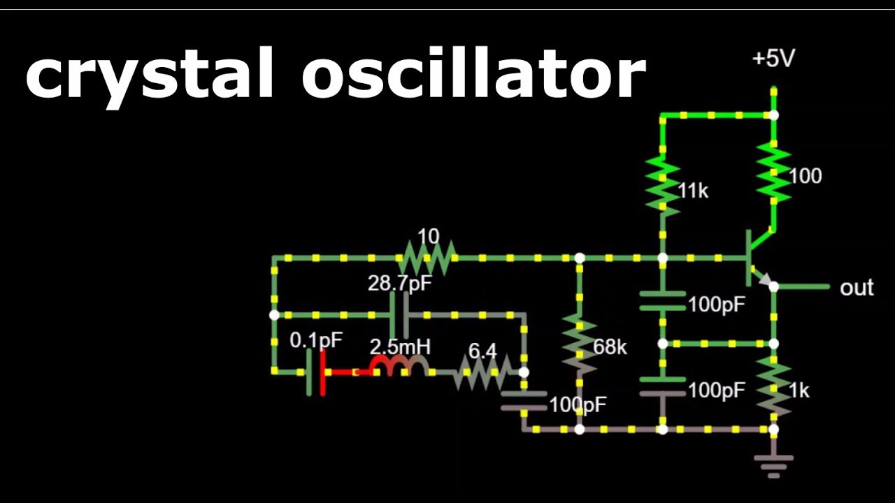
Crystal Oscillator- Quartz Crystal- Crystal Oscillator Circuit- Falstad Circuit Simulator- Oscillato

Crystal Oscillator Circuit Addendum

Crystal Controlled FM Transmitter
Overview of Crystal Oscillator Circuit Working with applications

Crystal-oscillator circuit is ultralow power - EDN

Crystal Tester Circuit using BC548 Transistor

Popular Crystal Oscillator Circuits
Very Simple Crystal Oscillator - CircuitLab
Design Crystal Oscillator Circuit

Quartz Crystal Oscillator and Quartz Crystals
Crystal Oscillator : Working and Its Various Applications
Crystal Oscillator Circuit: How to Build One

Understanding Crystal Oscillator Circuits - Homemade Circuit ...

Colpitts 1MHz To 20 MHz Crystal Oscillator Circuit ...
Solid State Circuits 2
Overview of Crystal Oscillator Circuit Working with applications
crystal oscillator circuits
![CRYSTAL OSCILLATOR CIRCUITS[Practical Oscillator Circuits]](https://www.industrial-electronics.com/images/393_babini_osc_6-2.jpg)
CRYSTAL OSCILLATOR CIRCUITS[Practical Oscillator Circuits]
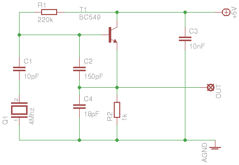
Tutorials – 4MHz Colpitts Crystal Oscillator | NewioIT

Colpitts Crystal Oscillator Circuit - Forum - Passive ...
Transistor Crystal Oscillator circuit ideas | ElecCircuit.com
Crystal Oscillator
Series Parallel Crystal Oscillator Circuits

TEMPERATURE CONTROL CIRCUIT OF OVEN CONTROLLED CRYSTAL ...

Crystal Oscillator: Circuit, Frequency & Working Principle ...


Comments
Post a Comment