41 map sensor diagram
Arduino&Soil Moisture Sensor-Interfacing Tutorial-Circuit ... 31/10/2020 · In this article, we are going to interface a Soil moisture sensor FC-28 with Arduino. This sensor measures the volumetric content of water inside the soil and gives us the moisture level as output. The sensor is equipped with both analog and digital output, so it can be used in both analog and digital mode. FreeASEStudyGuides.com | MAP Sensor Circuit Q and A Component A in the diagram above is: A. A connection in the signal circuit of the MAP sensor. B. A splice in the signal circuit of the MAP sensor. C. A splice in the ground circuit of the MAP sensor. D. A connection in the reference circuit of the MAP sensor.
MAP Sensor: Working, Structure and Types - Utmel Manifold Absolute Pressure Sensor, referred to as MAP sensor. The MAP sensor is an indirect airflow meter, and its signal is one of the important signals for the basic fuel injection control of the engine. It is connected to the intake manifold with a vacuum tube. With different engine speed loads, it senses the vacuum change in the intake manifold and then converts the change in the internal resistance of the sensor into a voltage signal for the ECU to correct the fuel injection volume. In the electronic fuel injection engine, the MAP sensor is used to detect the intake air volume is called the D-type injection system (speed density type). The MAP sensor detects the intake air volume not directly like the intake airflow sensor but uses indirect detection. At the same time, it is also affected by many factors, so there are many differences in the detection and maintenance of the intake airflow from the volume sensor.

Map sensor diagram
Map sensor wire diagram - Fixya SOURCE: need wiring diagram for map sensor for 1993 850 If its a three wire sensor one is a ground , one is the 5 volt refrence and the other one is the signal .Key on the 5 volt refrence shuld be about 4.8 signal should be under 1 but above .5 Map sensor issues ... Help - Dodge SRT Forum The only way to get a P0108 (signal voltage over 4.92v) is bad wiring or bad MAP sensor. Since you've replaced the MAP, it has to be the wiring. If the connector looks ok, make sure the wiring at the PCM is good. It was common practice to splice in a pos piggy back controller into the MAP signal wire to the PCM. Symptoms of a Bad MAP Sensor, and How to Test One However, these symptoms are not exclusively symptoms of a failed MAP sensor. Sometimes, a bad sensor may trigger the check engine light (CEL). If a trouble code has been stored on the computer memory indicating a problem with the MAP sensor, it's a good idea to actually test the sensorm to confirm that the problem lies with the sensor and not some other related component.
Map sensor diagram. Honda Map Sensor Wiring Diagram Pdf - IOT Wiring Diagram Honda Car Pdf Manual Wiring Diagram Fault Codes Dtc. 3 Bar Map Sensor Wiring Toyota Gr86 86 Fr S And Subaru Brz Forum Owners Community Ft86club. Part 2 How To Test The Map Sensor 1 5l Honda Civic. Ignition System Wiring Diagram 1996 1997 2 2l Honda Accord Ex. 1996 1998 Throttle Position Sensor Circuit Diagram 1 6l Civic. WHERE IS YOUR MAP SENSOR LOCATED. MOST CARS - YouTube WHERE IS YOUR MAP SENSOR LOCATED. MOST CARS Check out our Amazon store for the tools that we use in our videos: ... Part 1 -How To Test The MAP Sensor (1999-2006 V8 Chevrolet ... 1. Remove the MAP sensor from the intake manifold. If you had to disconnect the MAP sensor from it's electrical connector to remove it, reconnect it now (the MAP sensor must remain connected to its connector for this test). 2. Connect the vacuum pump to the MAP sensor's vacuum inlet port. Manifold Absolute Pressure Sensor (Map Sensor) MAP sensor (MAP) measures dilution in the intake manifold and its sensitive element converts the signal to electrical that can be returned to the onboard controller. MAP sensor is used mostly as a cheap alternative to sensors for engine load. Its relatively low cost is the reason for its wide distribution, though its measurements are not as ...
A MAP Sensor : Working, Function and Application Aug 09, 2021 · The manifold absolute pressure sensor (MAP sensor) is one of the sensors used in the electronic control system of an internal combustion engine. MAP sensors are frequently used in engines that inject fuel. The manifold pressure sensor transmits real-time manifold pressure data to the engine's electronic control unit (ECU). 1996-1998 MAP Sensor Circuit Diagram (1.6L Civic) MAP Sensor Wiring Diagram. NOTE: The manifold absolute pressure (MAP) sensor wiring diagrams and info in this page apply only to 1996, 1997, 1998 1.6L Honda Civic. The MAP sensor on your Civic can be tested with just a multimeter (no scan tool required). The following tutorial will help you with the test procedure on a step-by-step manner: Honda Map Sensor Wiring Diagram - Wiring Diagram Line 1996 1998 map sensor circuit diagram 1 6l civic wiring team integra forums part how to test the honda p1129 a my pro street help in obd1 tech forum discussion dtc p0107 measure accord signal need 92 95 diffeiate from tps acura k20a k24a engine png images pngegg fungsi dan cara kerja lengkap beserta gambarnya https meisetio com cb7 h22a swap 5l ... MAP Sensor & Wiring Diagram - YouTube | Map sensor, Map ... Part 2 of 3: MAP Sensor Test (P0106, P0107, P0108) (GM 4.3L, 5.0L, 5.7L). TEST 1: Verifying the MAP Signal with a Multimeter. TEST 2: Verifying the MAP Sensor Has Power. Testing the MAP Sensor With a Multimeter. MAP Signal Test.
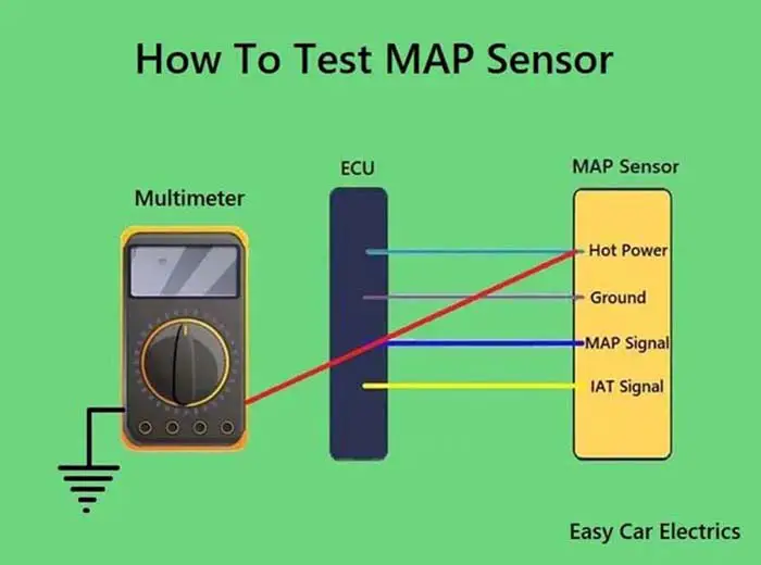
Map Sensor Wiring Diagram - 4K Wallpapers Review 1996 1998 map sensor circuit diagram 2 find maf iat and map sensor wires 1998 2001 map sensor circuit diagram 1 3 & 4 Pin MAP Sensor Wiring Diagram - Easy Car Electrics 3 Wire MAP Sensor Wiring Diagram A three-wire MAP sensor has three wires, power, ground, and signal, which are listed below. Hot Power Wire (5 Volt Reference Voltage comes from the ECU) Ground Wire Signal Wire (Gives Signals to the ECU) The hot wire is a feed power source that is connected to the car computer (ECU). A Simple MAP/MAF Enhancer - FuelSaver-MPG The Basics. First lets clarify some basics. MAP = Manifold Absolute Pressure. A MAP sensor measures the pressure in your intake manifold. MAF = Mass Air Flow. A MAF sensor measures the amount of air coming in to your engine. These devices are designed so similarly that a device that works for a MAP also works for a MAF. Function of the manifold pressure (MAP) sensor - Delphi Dec 18, 2019 — MAP Sensors. MAP sensor diagram. The Manifold Pressure Sensor is used in an engine's electronic control system. Engines that use a pressure ...
Kia Sportage: Manifold Absolute Pressure Sensor (MAPS ...
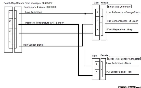
1996-1998 MAP Sensor Circuit Diagram (2.0L Neon) IAT/MAP Sensor Wiring Diagram (Part 1) NOTE: The IAT/MAP sensor wiring diagrams and info in this page apply only to 1996, 1997, 1998 Dodge/Plymouth SOHC/DOHC 2.0L. As you're already aware, the IAT/MAP sensor assembly is two sensors in one. One part is the intake air temperature (IAT) sensor and the other is the manifold absolute pressure (MAP) sensor.

Part 2 -How to Test the MAP Sensor (2002-2009 4.7L Dodge)
MAP Sensor & Wiring Diagram | Map sensor, Automotive ... Page 1 of 3: How to Test the Throttle Position Sensor (3.0L Mitsubishi Montero). Symptoms of a Bad Throttle Position Sensor. TEST 1: Testing the Throttle Position Sensor Voltage Signal. Get the 2022 auto wiring test while using simple tools! The latest 2022 auto wiring voltage drop test that top mechanics use.

Triumph SCHLAUCH, MAP-SENSOR, ZYL. 1&3. Triumph World Leibnitz
SOLVED: MAP sensor wiring diagram - Fixya Fig. Fig. 3: Location of the MAP sensor-TBI system shown. Fig. Fig. 4: Probe the terminals of the MAP sensor to check for proper reference voltage. Fig. Fig. 5: Manifold Absolute Pressure (MAP) sensor wiring diagram. TPS TESTINGSee Figures 2, 3 and 4. Backprobe with a high impedance voltmeter at TPS terminals A and B.
MicroSquirt® Introduction
What Is MAP Sensor, Its Function, Location & Working The manifold absolute pressure sensor measures the intake manifold pressure to calculate the intake air volume. Inside the MAP sensor, there is a sealed vacuum chamber that either has a perfect vacuum or a calibrated pressure and on the other side is the intake manifold air pressure to be measured.
MAP sensor wiring help PLEASE! - NA M3 Forums
Harley CV Carburetor Parts Diagram - CV Performance MAP SENSOR (Twin Cam and carbureted model XL) 1: 75.00: 59: 38723-99: CLIP, MAP SENSOR (Twin Cam and late model XL) 1: 5.55: 60: 62347-04: CVP 5/16 Hose: HOSE, 1/4 I.D. X 1/2 O.D. (VP 5/16 Hose) 1: 11.31: 61: 68042-99: SCREW: 1: 1.57--CVP-EZ001: IDLE MIXTURE SCREW (NOT SHOWN) - or EZ-Just Mixture Screw: 1: 21.95--CVP-MXPACK : IDLE …

OEM Original Denso Map Sensor 37830-pgk-a01 Für Honda Acura ...
3800 V6 Engine Sensor Locations Pictures and Diagrams Answer: In most cars, the vehicle speed sensor is located in the tail shaft housing of the transmission. This is where the axle comes out on the passenger side of the trans. On front wheel drive cars. Best viewed from under the car. Where is the map sensor on this 3800 GM v6? The MAP sensor is located in position 7 on the picture above.
1996-1998 MAP Sensor Circuit Diagram (1.6L Civic)
7 Symptoms of a Broken MAP Sensor This MAP sensor is mounted directly to the intake manifold, but others might be connected by a hose. Benji Jerew/Flickr/CC BY 2.0. The ECM uses MAP sensor data to run crucial calculations, such as engine load, fuel injector pulse, and spark advance. When at rest, the MAP sensor reads atmospheric pressure at sea level (29.93 in. Hg).

MAP Sensor & Wiring Diagram - YouTube
PDF BMW - electrical systems - WIRING DIAGRAM BMW - electrical systems - WIRING DIAGRAM Models covered: • 3-Series (E30) 316 (83 to 88), 316i (88 to 91), 318i (83 to 91), 320i (87 to 91), 325i (87 to 91).Also Touring and Convertible versions of these models • 5-Series (E28) 518 (81 to 85), 518i (85 to 88), 525i (81 to 88), 528i (81 to 88), 535i (85 to 88), M535i (85 to 88) • 5-Series (E34) 518i (90 to 91), 520i (88 to 91), 525i (88 ...
MAP sensor measurement
TMP36 Temperature Sensor Arduino Tutorial (2 Examples) 25/10/2020 · In this tutorial, you will learn how to use a TMP36 analog temperature sensor with Arduino. I have included a wiring diagram and several example codes to help you get started! In the first part of this article, you can find the specifications and information about the TMP35, TMP36, and TMP37 sensors.

Hose, Map Sensor
Voltage Sensor Module: Pinout, Interfacing Arduino ... Voltage Sensor Module Pinout. The voltage sensor module is embedded with two header blocks. One with the screws is connected to the power source whose voltage to be measured while the other connector is used to interface microcontrollers such as Arduino, Pic microcontroller, Raspberry Pi, Beaglebone, etc.

Manifold Absolute Pressure MAP Sensors
MAP and MAF sensor wiring diagram - NASIOC MAP and MAF sensor wiring diagram I'll use a stand alone ecu for my 07 EuroDM STI. I'm also replacing my intake air temp sensor with a delco sensor and connect the wires coming from the delco IAT sensor to the wiring of the MAF sensor since it has a built in IAT sensor. anyone know the wire config of the MAF sensor??

Symptoms of a Bad MAP Sensor, and How to Test One - AxleAddict
PDF WIRING MANUAL & DIAGRAMS 199R10555 - Holley A23 Map Sensor Input B23 EST 5 Output (Cylinder #5) A24 CAN Lo B24 EST 7 Output (Cylinder #7) A25 WB1 VS+ B25 Injector C Output A26 Sensor +5v B26 Injector B Output A27 NOT USED A28 EST/Spout Output A29 Knock #1 Input A30 Crank Speed Input A31 Fuel Pressure Input A32 CAN Hi

What are the bad MAP sensor symptoms and to detect them ...
MAP sensor measurement - TiePie-automotive With a lab scope a Manifold Absolute Pressure (MAP) sensor is measured under the following conditions: key on, cranking, idle, 2000 RPM, 3000 RPM and back to idle with an engine at operating temperature. The signal from the sensor is shown and can be downloaded. To help determining whether a MAP sensor is functioning correctly, different possible deviations from the example signal are ...

MAP sensor Wiring diagram Pressure sensor, others, electrical ...
MAP Sensor & Wiring Diagram - YouTube MAP Sensor & Wiring DiagramAmazon Printed Bookshttps:// Kindle Editionhttp:// ...

I am searching for 53 plate 2.0 tdci mondeo MAP sensor Wiring ...
Analog sensor wiring | Speeduino Manual The external MAP sensor in the above diagram is optional and may be omitted if the onboard MAP is used. Alternatively an external Baro sensor may be added in the same was as an external MAP; A 3 wire variable TPS is required. On/Off type throttle switches are not suitable ...
Lsj stock Map sensor Question from Becks M62 install ...
Map Sensor: Working Principle, Signs and Its Applications Map Sensor Working Principle. The MAP sensor is an input sensor which detects an engine load and provides a signal which is proportional to the sum of vacuum. After that, an engine computer utilizes this data to alter explosion timing & fuel enhancement. Whenever the engine works hard, ingestion vacuum falls because of the throttle releases wide.

Map sensor wiring Help - RX7Club.com - Mazda RX7 Forum
Symptoms of a Bad MAP Sensor, and How to Test One However, these symptoms are not exclusively symptoms of a failed MAP sensor. Sometimes, a bad sensor may trigger the check engine light (CEL). If a trouble code has been stored on the computer memory indicating a problem with the MAP sensor, it's a good idea to actually test the sensorm to confirm that the problem lies with the sensor and not some other related component.
How To Test MAP Sensor With & Without Multimeter
Map sensor issues ... Help - Dodge SRT Forum The only way to get a P0108 (signal voltage over 4.92v) is bad wiring or bad MAP sensor. Since you've replaced the MAP, it has to be the wiring. If the connector looks ok, make sure the wiring at the PCM is good. It was common practice to splice in a pos piggy back controller into the MAP signal wire to the PCM.

Manifold Absolute Pressure MAP Sensor - Toyota Engine Control ...
Map sensor wire diagram - Fixya SOURCE: need wiring diagram for map sensor for 1993 850 If its a three wire sensor one is a ground , one is the 5 volt refrence and the other one is the signal .Key on the 5 volt refrence shuld be about 4.8 signal should be under 1 but above .5

Map sensor - Link G4 - Link Engine Management Forums
Code 34 - Manifold Absolute Pressure (MAP) Sensor Circuit
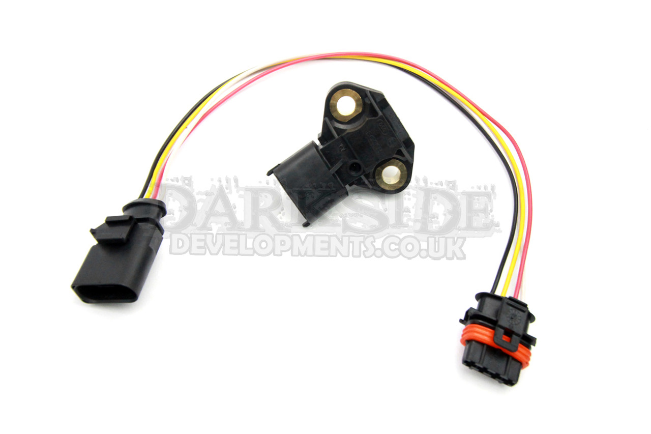
Bosch 6 BAR MAP Manifold Pressure Sensor with Wiring Harness Adapter

MAP Sensor: Working, Structure and Types - Utmel
Pcm to boost pressure sensor wiring diagram | Ford Focus ST Forum

MAP Sensor • MTE-THOMSON

G71 Drucksensor MAP Sensor für VW T4 Motorsteuergerät 105kPa 105 kPa überholt

Manifold Pressure MAP Sensor Wiring Pigtail Connector GM LS1 ...
MAP Sensor Wiring | Team Integra Forums

GM 3 bar map sensor calibration - G4+ - Link Engine ...

Link 3 Bar MAP Sensor (MAP3)

Speed Density and the MAP Sensor
1996-1998 MAP Sensor Circuit Diagram (2.0L Neon)

MAP Sensor & Wiring Diagram
map sensor wiring PLZ HELP! | VW Vortex - Volkswagen Forum

Amazon.com: 4-PIN MAP Sensor Connector & Harness Compatible ...
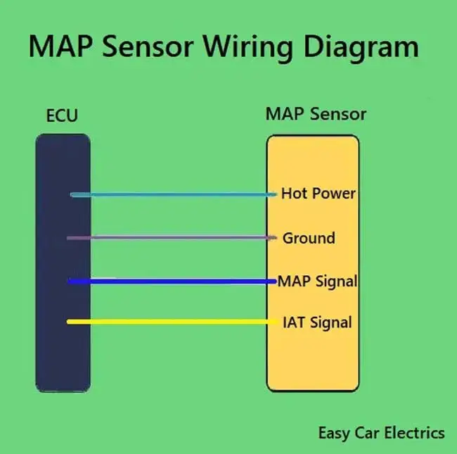
3 & 4 Pin MAP Sensor Wiring Diagram - Easy Car Electrics

3 Bar MAP Sensor For GM STYLE Megasquirt Motec Electromotive Turbo With Plug Wire 12223861 16040749
need diagram of stock map sensor pigtail - EvolutionM ...

Function of the manifold pressure (MAP) sensor | Delphi Auto ...
Can not find MAF, IAT and MAP sensor wires | Hyundai Forums

GM Map Sensors - 1 Bar, 2 Bar, 3 Bar - Wiring Harnesses
Comments
Post a Comment