41 refrigerator defrost timer wiring diagram
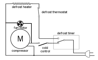
refrigerator - Understanding fridge wiring diagram - Home ... The defrost heater is clearly marked in the diagram, so it is extremely unlikely the "compartment heater" is used for defrosting. Most probably the compartment heater is for what used to be known as the "butter keeper" compartment, which maintains a slightly warmer temp than the rest of the fridge so that butter is not rock hard when you want to use it without waiting for it to soften after ... PDF Timer motor circuit DEFROST SYSTEMS - ApplianceAssistant.com timer only advances when the compressor is running. After the timer measures an accumulated run time equal to a predetermined amount, the system will enter into the defrost cycle. This type of defrost is often referred to as a cumulative run-time defrost. Even the cumulative defrost systems fail to account for the number of times the door is opened
Refrigerator Defrost Timer Wiring Diagram Collection ... refrigerator defrost timer wiring diagram - A Beginner s Overview of Circuit Diagrams A very first look at a circuit diagram may be confusing, however if you can check out a train map, you can review schematics. The function is the same: getting from factor A to point B. Literally, a circuit is the path that allows electricity to circulation.

Refrigerator defrost timer wiring diagram
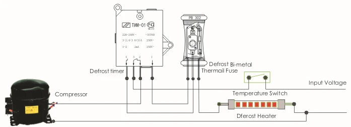
Refrigerator Repair and defrost timer wiring diagram - YouTube In this video you can learn about the defrost timer wiring diagram of a frost free refrigerator and circuit diagram Step by step details about the function o... Domestic Refrigerator Wiring | Hermawan's Blog ... Terminal 1gain power from the blue line through the defrost heater while terminal 3 connected to terminal 4 to compressor.When the terminal 3 connected to terminal 2 in defrost mode timer will stop until the bimetal cut out.Most refrigerator japan made use this kind of wiring diagram. Freezer Defrost Timer Wiring Diagram This refrigerator defrost timer kit is designed to fix issues with your refrigerator temperature as well as symptoms such as the defrost cycle not working, build up of ice in /5(15).Paragon Defrost Timer wiring diagram - Questions (with Pictures) - Fixya[WRGFree Ebook] Defrost Timer Schematic | Trusted Manual & Wiring Resources
Refrigerator defrost timer wiring diagram. Domestic Refrigerator Wiring | Electrical wiring diagram ... D frosting timer is placed in this refrigerator. So that the refrigerator cooling for about 8 hours and heater […] student. cooling. Basic Electrical Wiring. Ac Wiring. Electrical Circuit Diagram ... 50 Best Of Compressor Start Relay Wiring Diagram- A control relay is used in the automotive industry to restrict and alter the flow of ... FIXED - Frigidaire Mini Refrigerator Defrost Timer ... The defrost timer decides whether to send L1 to the compressor or to the defrost heater. L1 comes into the defrost timer at the common terminal (Brown wire). The defrost timer motor turns the cam and the cam opens or closes the contacts to complete either a defrost circuit or a compressor run circuit. The diagram above is your machine and ... Commercial Refrigeration Wiring Diagrams - easywiring Retail store walk in coolers and freezers boiler operating control used as a thermostat universal defrost timer wiring. Wiring diagram a schematic drawing of the wiring of an electrical system. This type of wiring diagram has branch runs all shown as parallel circuits going from the left line l1 to the neutral line n. Paragon Defrost Timer Wiring Diagram - Wiring Systems The Paragon Series Auto Voltage Defrost Timer is designed competitive voltage-specific mechanical defrost timers eliminating Wiring Diagrams. Paragon Timer Wiring Diagram. Domestic Refrigerator Wiring Circuit Diagram Electrical Wiring Diagram Refrigeration And Air Conditioning Then timer outputs can control 3-phase power using 3-phase contactors Contactor below is 3 phase with V coil http ...
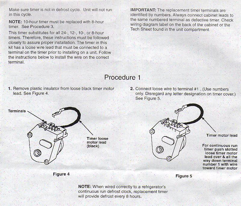
grasslin control defrost timer wire diagram - Wiring ... Grasslin Control Defrost Timer Wire Diagram. ... dtav40q mech meier supply co inc master bilt 19 00816 unit bracket with clock appliance411 faq how does frost free refrigerator system work dtav40e2 electronic 1 min hr 7 days 240 vac spdt spst grässlin uk ltd basic sink ground fault circuit breaker outlet 365 gra 2004 witt b wi 010 011b ... Wiring Diagram For Defrost Timer - Wiring Diagram Line مختبر شديدة باسم sankyo defrost timer wiring diagram thislife org refrigerator comfort cool aircondition facebook precision multiple controls official ... 483212 defrost timer wiring - Appliance Repair Forum ... Joined: 11/5/2011 (UTC) Posts: 2. The part replacement for the defrost timer has a black wire that was not on the original part. I have confiremd that this is a replacement but the are options for the black wire depending up the original wiring diagram of the unit. I chose version2/procedure 3 as it seemed to fit. Refrigerator Defrost Timer Wiring Diagram Collection ... DOWNLOAD. Wiring Diagram Pics Detail: Name: refrigerator defrost timer wiring diagram - Supco 3 In 1 Wiring Diagram Fresh Walk In Freezer Defrost Timer Wiring Diagram Webtor. File Type: JPG. Source: thespartanchronicle.com. Size: 475.16 KB. Dimension: 2533 x 1780. DOWNLOAD. Wiring Diagram Images Detail:
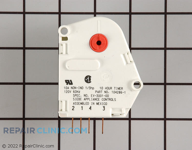
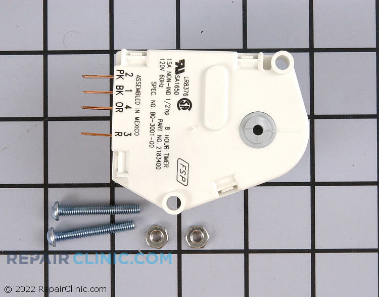
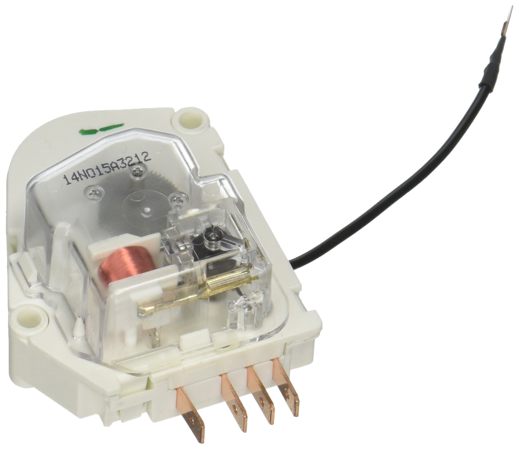
W10822278 Wiring Diagram - schematron.org W10822278 Wiring Diagram. Whirlpool Genuine OEM W Refrigerator Defrost Timer Kit. This timer will activate for 21 minutes every 8 hours. This timer kit is designed for both. Kenmore Refrigerator Defrost Timer W - This eight-hour defrost timer So I figured my model was too old, the wiring diagram was simalar to mine on. Reading wiring diagrams: How the Defrost Cycle works in a ... Brother Reg elegantly steps us through the circuit diagram for this one. When the Defrost cycle starts (Timer Motor pauses),the Neutral goes through the Defrost Heater, Defrost Thermostat, and Thermal Fuse to Line.Whenever the Defrost Thermostat "opens",the Neutral still goes through the Defrost ... Wiring Diagram Frigidaire Defrost Timer 21546602 FOR FRESH FOOD THERMISTOR AND DEFROST THERMISTOR. °F Operating Time.defrost. With the notch on the timer knob aligned with the line on the bracket (Fig. A), turn the defrost timer knob clockwise slowly. The timer will click several times, then once loudly, at which point the defrost cycle begins. W10822278 Wiring Diagram W10822278 Wiring Diagram. Kenmore Refrigerator Defrost Timer W - This eight-hour defrost timer So I figured my model was too old, the wiring diagram was simalar to mine on. I do not have a wiring diagram. ANSWER Hello Ken, You will need to connect the black jumper wire on the defrost timer W to pin. Whirlpool W Refrigerator Defrost Timer ...
I have a Kelvinator NB400H refrigerator and the defroster is ...
Whirlpool Refrigerator Wiring Diagram - Wirings Diagram Whirlpool Refrigerator Wiring Diagram - whirlpool double door refrigerator wiring diagram, whirlpool fridge freezer wiring diagram, whirlpool fridge thermostat wiring diagram, Every electrical arrangement consists of various distinct parts. Each part ought to be placed and linked to different parts in specific manner. If not, the structure won't function as it should be.
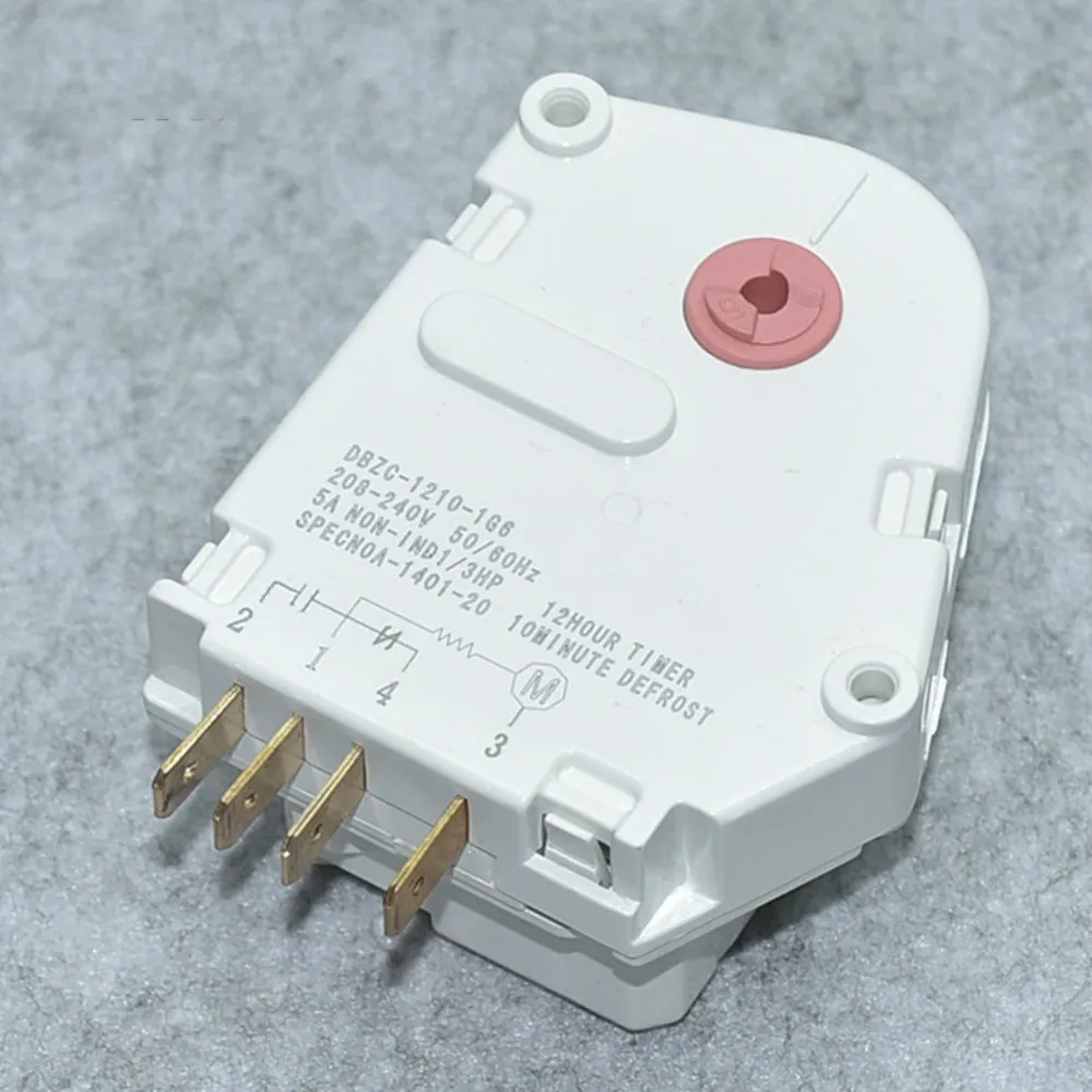
Original brand new Haier refrigerator Parts defrost timer DBZC-1210-1G6 refrigerator defrosting timer DBZC1210-1G6
universal defrost timer wiring - Appliance Repair Forum ... Joined: 7/29/2009 (UTC) Posts: 4. I have a question about the wiring for defrost timers in general. from what I've gathered most of them have 4 terminals. 1 for a common feed, one going to the defrost heater, 1 goes either to the compressor or in my case the thermostat first then the compressor and the other looks like it might monitor the ...
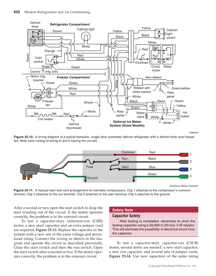
Modern Refrigeration and Air Conditioning, 20th Edition Page ...
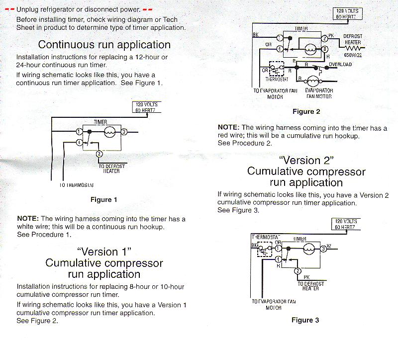
106.56622500 Where do I put the black wire terminal on a ... Whirlpool defrost timers only! When I was a little unsure about hooking those defrost timers up, where the timer motor wire went , #1 terminal or # 2 terminal. Whirlpool tech line gave me an easy way out: If the timer has a WHITE wire going to it ,the timer lead goes on #1 Anything else goes on #2

R0131577 Whirlpool Defrost Timer
Whirlpool Refrigerator Defrost Timer Wiring Diagram ... Whirlpool Refrigerator Defrost Timer Wiring Diagram Free Download 2022 by russell.reichert. Find The BestTemplates at vincegray2014.
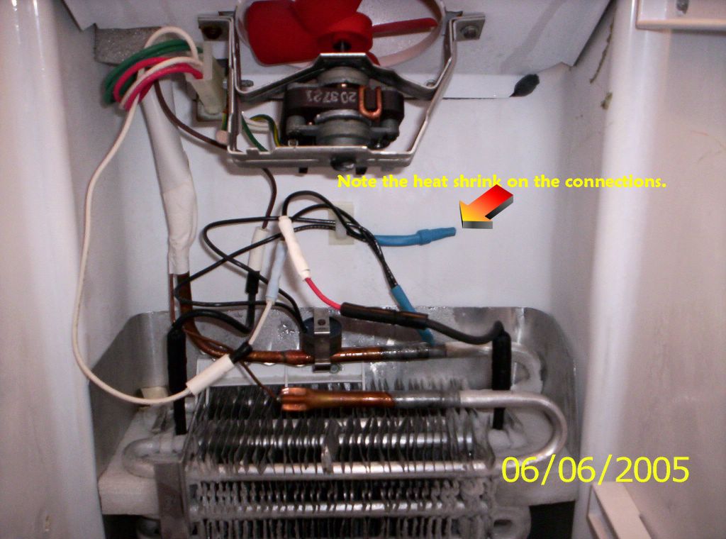
Technique of the Master: Wiring in a New Defrost Thermostat ...
Wiring Diagram Frigidaire Defrost Timer 21546602 The instructions suggest comparing it with the wiring diagram of the freezer for proper hook up. Defrost Timer - 60Hz V - Frigidaire - Defrost timers are part of the defrost circuit in your refrigerator and freezer. The timer is connected into a wiring harness in the housing with a drain tube that goes into the back of the fridge.

Whirlpool refrigerator timer - DoItYourself.com Community Forums
Samsung Refrigerator Defrost Timer Wiring Diagram ... Samsung Refrigerator Defrost Timer Wiring Diagram Free Download 2022 by mervin.ryan. Find The BestTemplates at vincegray2014.

Paragon Defrost Timer 8hr 7min for Refrigerator units
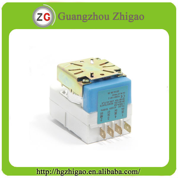
PDF Commercial Refrigeration Temperature and Defrost Controls The Latest Paragon® Defrost Timer • Universal Defrost Timers (UDT) • Works with multiple voltages • Removes built up of ice and frost • Easy to install • Simple to program • Part 9145-00 temp terminated • Part 9045-00 time terminated • Available as mechanism only without case - Add "M" to end of part number
Commercial Refrigeration Temperature and Defrost Controls
Paragon Timer Wiring Diagram For Freezer - Wire Paragon 20 wiring diagram wallmural img source. Paragon sell sheet shows model numbers and wirings diagrams replace with tt or ct series. Walk in freezer defrost timer wiring diagram wiring diagram is a simplified suitable pictorial representation of an electrical circuit it shows the components of the circuit as simplified shapes and the skill ...

DEFROST TIMER CIRCUITS SCHEMATIC DIAGRAM SAMPLE AND ...
Whirlpool W10822278 Defrost Timer (AP5985208 ... If the timer is not working, it will need to be removed and replaced.The defrost timer is found in the refrigerator's control housing, usually on the refrigerator's back. Disconnect the power supply before removing the panel cover. Locate the defrost timer and disconnect the wiring. Pull it out of the refrigerator and install the new timer.

Defrost timer suitable for Videocon
refrigerator defrost timer wiring diagram - Wiring Diagram ... Sketch Wiring Diagram Of Dwelling House Pour Android Téléchargez L. Precision Multiple Controls Official Website Your Source For Energy Saving Photocontrols. China Supco Heavy Duty 8 Hours 25 Minutes Refrigerator Tmdc Defrost Timer 825 1 And. Fixed Frigidaire Mini Refrigerator Defrost Timer Replacement Help W10822278 Uet120 Dbyc903bl Page 3 ...

Triplel (triplel1979) - Profile | Pinterest
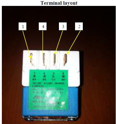
Where's the wiring diagram for my Kenmore refrigerator ... Looking at the timer, you should have a black wire, orange wire, pink wire and a red wire. The black wire is the main power wire. The pink wire is going to the defrost heater. The orange wire goes to the thermostat and the red wire goes to the motors. On the diagram that is on a film card, I looked for your model and that was the way it is wired.
Defrost Timer
Freezer Defrost Timer Wiring Diagram This refrigerator defrost timer kit is designed to fix issues with your refrigerator temperature as well as symptoms such as the defrost cycle not working, build up of ice in /5(15).Paragon Defrost Timer wiring diagram - Questions (with Pictures) - Fixya[WRGFree Ebook] Defrost Timer Schematic | Trusted Manual & Wiring Resources
How To Test the Defrost Timer - Refrigerator Repair Guide ...
Domestic Refrigerator Wiring | Hermawan's Blog ... Terminal 1gain power from the blue line through the defrost heater while terminal 3 connected to terminal 4 to compressor.When the terminal 3 connected to terminal 2 in defrost mode timer will stop until the bimetal cut out.Most refrigerator japan made use this kind of wiring diagram.
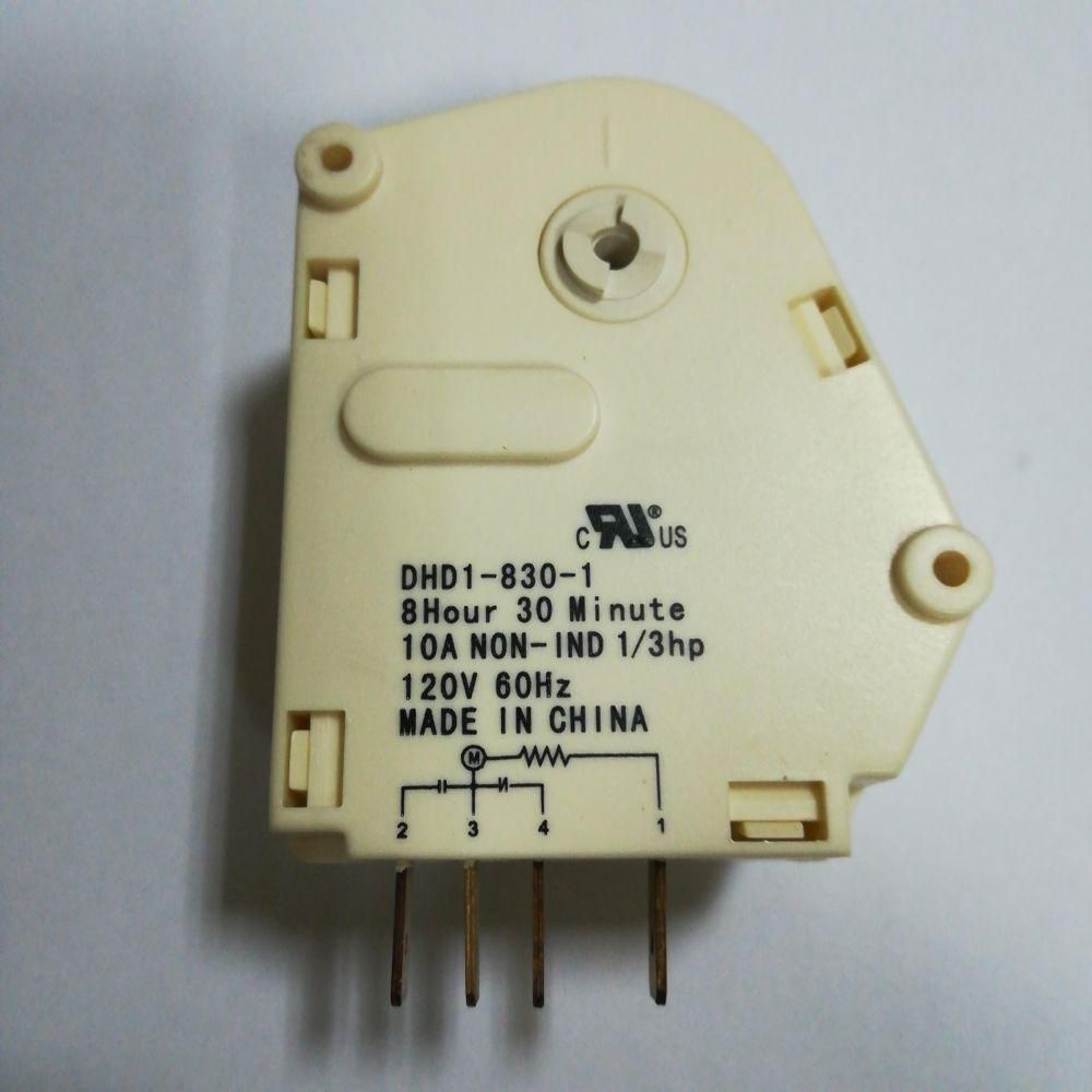
Refrigerator defrost timer (DHD1-830-1) 8 HOUR 30 MINUTES ...
Refrigerator Repair and defrost timer wiring diagram - YouTube In this video you can learn about the defrost timer wiring diagram of a frost free refrigerator and circuit diagram Step by step details about the function o...
Appliance411 FAQ: How does a Frost Free Refrigerator's ...
Fridge Refrigerator Defrost Timer Thermostat Temperature ...
DBLT-10 defrost timer for refrigerator freezer - Coowor.com
Defrost Timer
Defrost Time Controls / HVAC/R Defrost Time Controls / HV AC/R
GENUINE WHIRLPOOL TD-20C DEFROST TIMER

Comfort Cool Ref & Aircondition Engineering Service - Posts ...

DEFROST TIMER CIRCUITS SCHEMATIC DIAGRAM SAMPLE AND ...

Whirlpool refrigerator defrost timer issue - DoItYourself.com ...
Whirlpool Refrigerator Defrost Timer | Appliance Aid
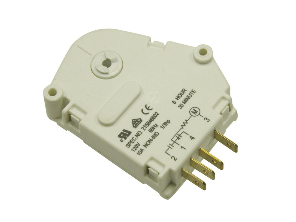
ForeverPRO 215846602 Refrigerator Defrost Timer for Frigidaire Refrigerator 5304457327 5300628518 00624728 00626234

How Does a Defrost Timer Work? | Appliance Repair Specialists
Refrigerator Defrost Timer TD20C - Coowor.com

WP482493 for Whirlpool Refrigerator Defrost Timer Control PS376605 AP3110896
Whirlpool Refrigerator Defrost Timer | Appliance Aid

China Supco Heavy Duty 8 Hours 25 Minutes Refrigerator Tmdc ...
FIXED - FRT045GM Defrost Timer Question | Page 2 ...

Refrigerator technician - wiring diagram auto frost | Facebook

DEFROST TIMER 6HR RUN / 30MIN DEFROST 220V : MacSpares ...

Typical wiring for defrost on a single evaporator freezer
Whirlpool W10822278 Refrigerator Defrost Timer- Buy Online in ...

Diagram circuit: Refrigerator Wiring Diagram Defrost Timer ...
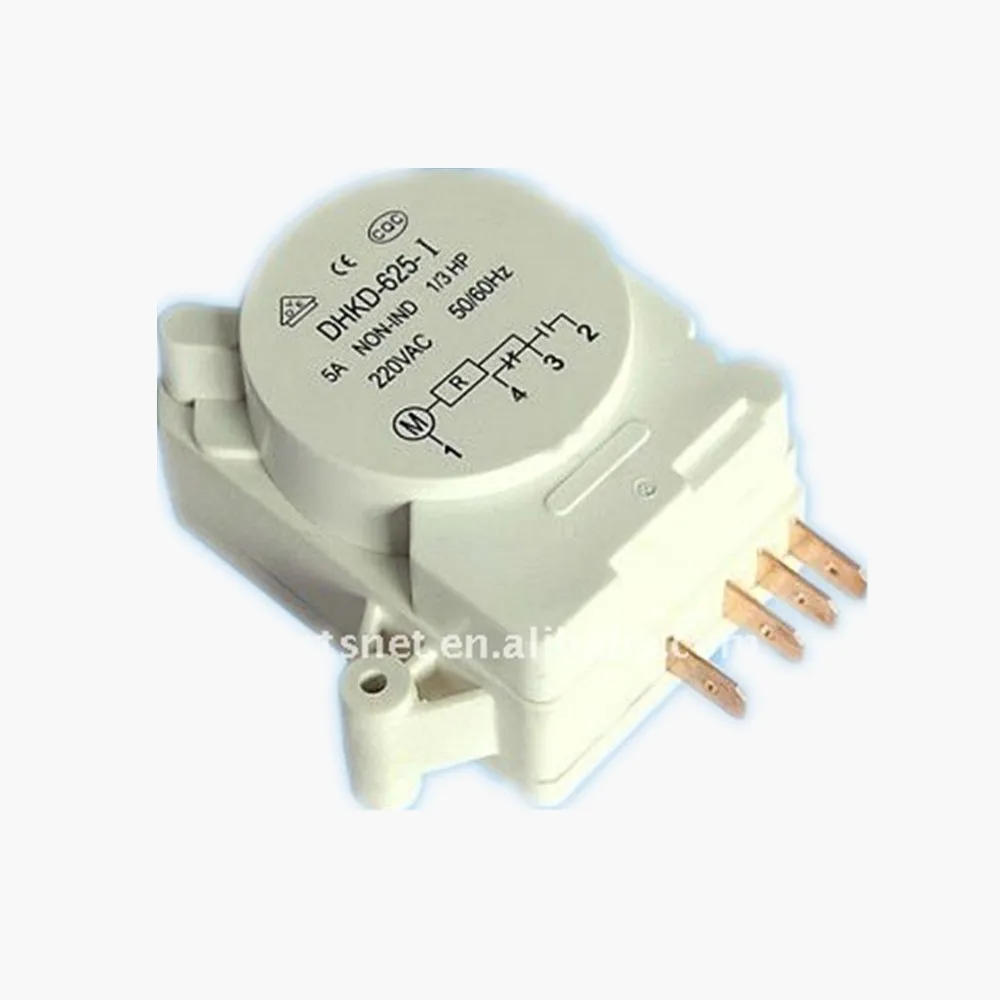
Ds-014 Refrigerator Defrost Timer / Dhkc Timetable Defrost ...
FIXED - Frigidaire Mini Refrigerator Defrost Timer ...

Precision Multiple Controls Official Website - Your Source ...

SOLVED: Refrigeration ynit not going into defrost, I need - Fixya

Buy WR9X520 Refrigerator Defrost Timer GE WR9X481 AP2061721 ...


Comments
Post a Comment