43 4 pin relay wiring diagram horn
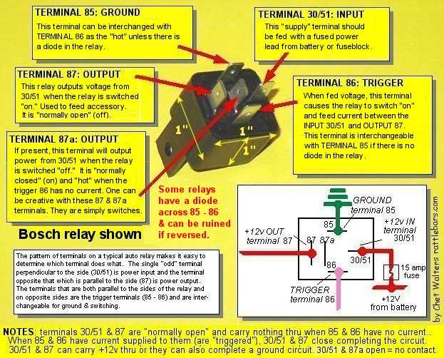
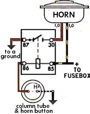
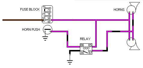
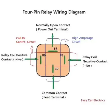
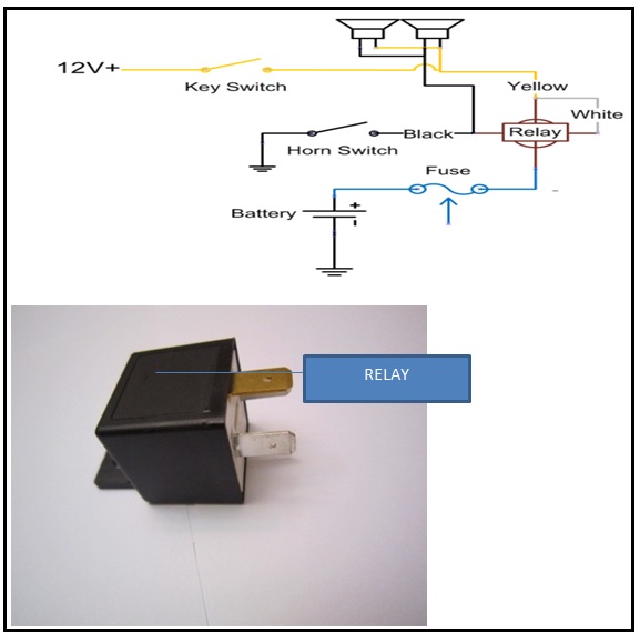
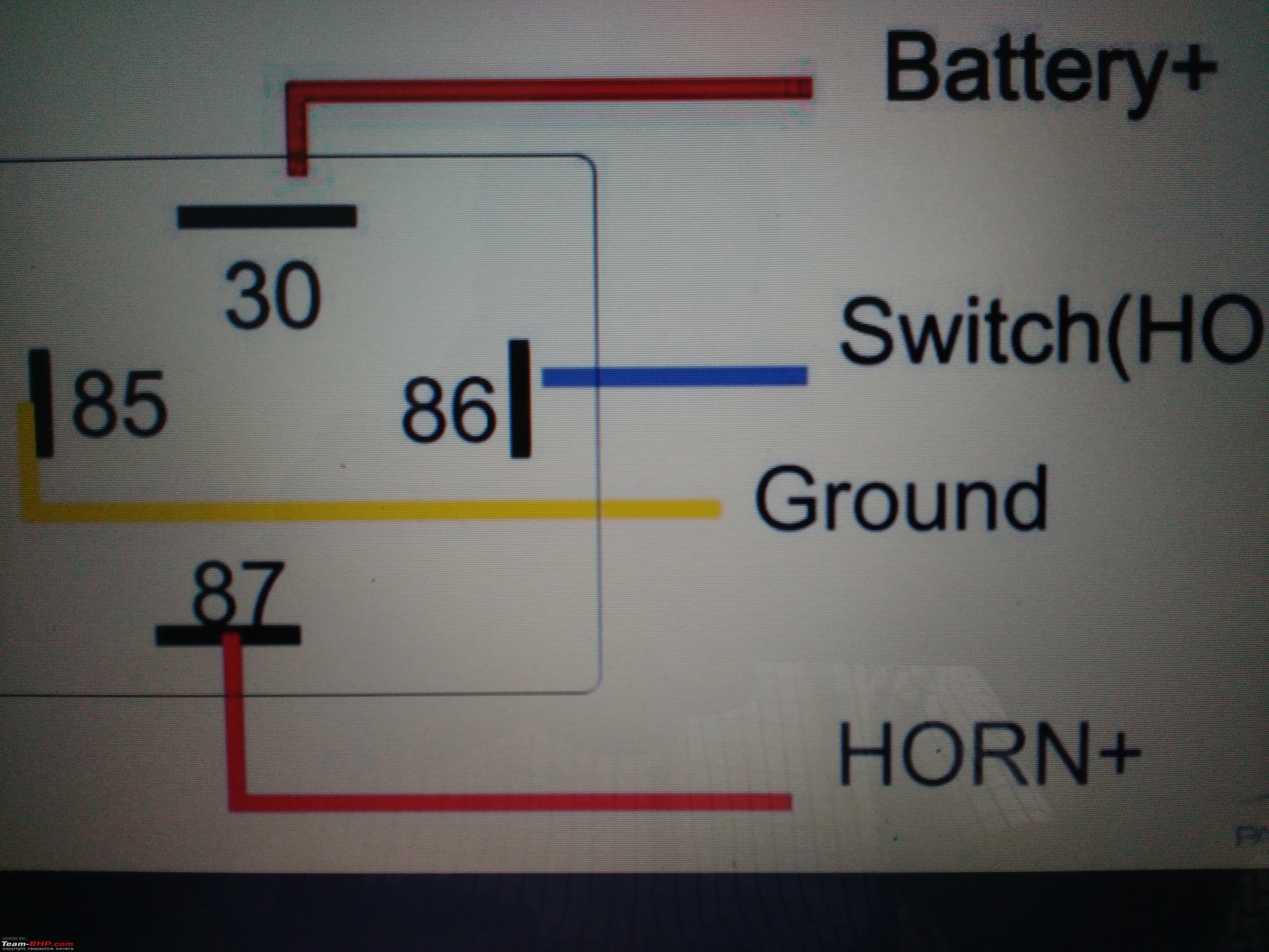
how to wire a 4 pin relay - shapovmusic.com 4 pin relays use 2 pins (85 & 86) to control the coil and 2 pins (30 & 87) which switch power on a single circuit. There are 2 types of 4 pin relay available; normally open or normally closed. A normally open relay will switch power ON for a circuit when the coil is activated. Automotive Relay Diagram! 4 & 5 Pin Relay Wiring Diagram 4 Pin Relay Wiring Diagram For Horn 4-Pin-Relay-Wiring-Diagram-For-Horn The relay coil circuit's terminal 86 is connected to the battery positive power source, while terminal 85 is connected to the steering wheel horn pad, which is a ground power source. And
4 Pin Relay Wiring Diagram - Wiring Diagram Automotive Relay Wiring Diagram Horn | Wiring Diagram - 4 Pin Relay Wiring Diagram Wiring diagram also provides beneficial recommendations for assignments that may require some additional tools. This e-book even includes ideas for extra supplies that you may want to be able to finish your tasks.

4 pin relay wiring diagram horn
4 Pin Relay Wiring Diagram Horn - easywiring connect a solderless ring terminal to one wire from the inline fuse holder and connect it to the positive terminal on the vehicle battery. 4 pin relay wiring diagram horn wiring diagram is a simplified satisfactory pictorial representation of an electrical circuit it shows the components of the circuit as simplified shapes and the capability and … Trailer Wiring Diagram 4 Pin - Wiring Sample The most common 4 wire connector is the 4 pin flat connector as shown here. Can also be used as custom wiring on trailers with 3 light wire systems. 4 Pin Relay Wiring Diagram Lights Relay Car Horn Automotive Electrical . 4 pin connectors 4 pin connectors are the standard used for most trailers. Trailer wiring diagram 4 pin. Tail lights brake ... electrical - Wiring a 3 pin relay to power a dual horn ... I am trying to implement a dual horn setup for my bike. The stock came with a single horn. I have with me a 3-pin relay(H-B-S) with me. I am connecting the positive from the battery to the B terminal, Horns connected to the H terminal (horns are grounded on the other end).
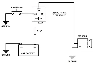
4 pin relay wiring diagram horn. VW - Car PDF Manual, Wiring Diagram & Fault Codes DTC I need detailed wiring color diagram for fuse relay box under hood 2005 lexus es330 zoomer939320@gmail.com #361. ... horn wiring diagram for Toyota auris 2008 model #359. Liz (Wednesday, 20 October 2021 02:55) I need a great wall steed Ute 2018 service log book and manual please #358. Carla McClinton (Friday, 15 October 2021 15:34) I need manual for 1993 … 2007-2011 Chevrolet Silverado Vehicle Wiring Chart and Diagram listed below is the vehicle specific wiring diagram for your car ... @ horn switch or bcm, brown plug, pin 18, see note #2 : tach: any wire not pink, pink/black or pink/white (ac), see note #4 @ any fuel-injector : wait to start light: dk. blue (-) @ instrument cluster, black 20-pin plug, pin 17 : brake: lt. blue/white (+) (test with ignition on) @ brake pedal switch or bcm, brown plug, pin 6 ... HOLDEN - Car PDF Manual, Wiring Diagram & Fault Codes DTC wiring flow chart for asd relay 06 liberty #430. James suresh (Friday, 14 ... horn wiring diagram for Toyota auris 2008 model #359. Liz (Wednesday, 20 October 2021 02:55) I need a great wall steed Ute 2018 service log book and manual please #358. Carla McClinton (Friday, 15 October 2021 15:34) I need manual for 1993 Panoz roadster #357. Bongani (Thursday, 14 October … 12 Volt Horn Relay Wiring Diagram - Wiring Diagram Vxk7801 4 pin horn relay with plug. 12 volt horn wiring diagram see more about 12 volt horn wiring diagram 12 volt horn relay wiring diagram 12 volt horn wiring diagram. Using a 30 amp spdt relay connect terminal 87 to constant 12 volts positive with a fuse rated to the sum of the additional accessories youve added and the components you need ...
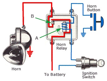
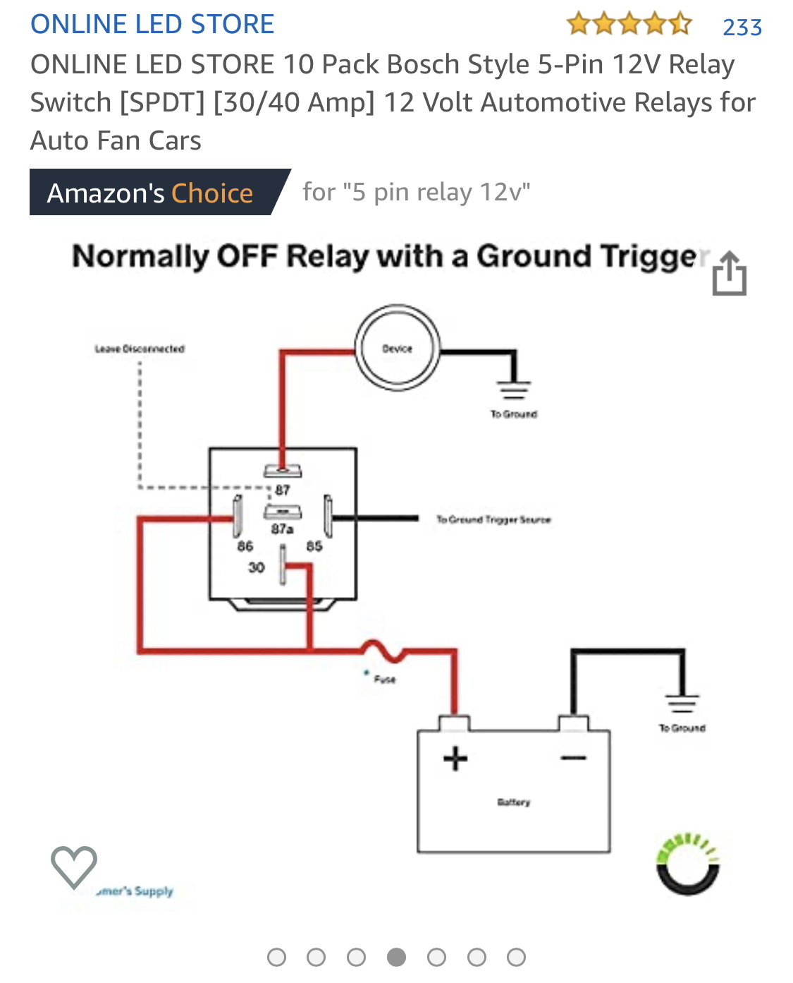
› Subaru_EE20_EngineSubaru EE20 Diesel Engine - australiancar.reviews Subaru's EE20 engine was a 2.0-litre horizontally-opposed (or 'boxer') four-cylinder turbo-diesel engine. For Australia, the EE20 diesel engine was first offered in the Subaru BR Outback in 2009 and subsequently powered the Subaru SH Forester, SJ Forester and BS Outback. Fuses, Relays & Earth Points - MINI Cooper Forum 01.11.2015 · 4 Connectors:-X332 20 pin (green) X253 54 pin (black) X254 54 pin (natural) X255 54 pin (blue) IDs for Relays / Location K42 Horn relay / Behind Passenger compartment fusebox K4 Heater-blower relay (up to March 2003) / Engine compartment fusebox K4 Heater-blower relay (from March 2003) / Passenger compartment fusebox Control: BC1 (X253 23) Switch: … How to Wire a Relay Diagram 4 Pin [Horn & Light] - EvsHunt How The Four PIN Relay Works for Horn The horn relay will start working by simply pressing the steering wheel horn button. The battery positive power sources will get connected every time with the relay terminal 86 of the coil circuit. When someone presses the steering wheel horn pad of the 85 terminal then the relay coil circuit gets energized. 12v Relay Wiring Diagram 5 Pin For Horn - U Wiring Pins 85 and 86 are connected to the 12v coil that operates the SPDT switch. 4 Pin Relay Wiring Diagram Horn Horn Relay Connection Diagram in Horn Relay Diagram Wiring image size 800 X 614 px. The spots has a seperate 4 pin relay I checked the following and even. The Bosch 5 pin relay is a SPDT Single Pole Double Throw switch.
4 Prong Relay Wiring Diagram - Wirings Diagram According to previous, the lines at a 4 Prong Relay Wiring Diagram signifies wires. At times, the cables will cross. But, it does not mean connection between the cables. Injunction of two wires is usually indicated by black dot in the junction of two lines. There will be primary lines which are represented by L1, L2, L3, and so on. Amazon.com: Vixen Horns 4-PIN Horn Relay 30A/12V with 4 ... FARBIN 12V 80a Horn Wiring Harness Relay Kit and Horn Push Button with 3 Meters Wire (wiring harness+button, 12V) 4.1 out of 5 stars 329 1 offer from $13.99 4 Pin Relay Wiring Diagram With Switch - easywiring Normally open or normally closed. 4 pin relay wiring diagram horn wiring diagram is a simplified satisfactory pictorial representation of an electrical circuit it shows the components of the circuit as simplified shapes and the capability and signal contacts in the company of the devices. 4 Pin Relay Wiring Diagram - U Wiring Wiring Diagram for A 4 Pin Relay wiring diagram is a simplified agreeable pictorial representation of an electrical circuitIt shows the components of the circuit as simplified shapes and the capacity and signal connections with the devices. So a single pole double throw has a mutual.
HORN RELAY ANIMATION - YouTube
› wiring › 2006-2006- Dodge Ram Vehicle Wiring Chart and Diagram see note #4 : in each kick panel or instrument cluster, large gray plug : domelight supervision: yellow/light blue (+) @ a pillar or instrument cluster, white plug, pin 21 : trunk release: n/a : sliding power door: n/a : horn: dark green/purple (-) @ horn switch or instrument cluster, large gray plug, pin 14 : tach: dark blue/gray (ac), see note #5

Horn Relay Simple Wiring Youtube – Otosection
4 Pin Relay Wiring Diagram Horn - The Wiring 4 pin relay wiring diagram horn. This is a typical wiring diagram for a standard relay installed for headlights, horn, fuel pump, electric fan, etc. May 11, 2018 - Bosch 4 Pin Relay Wiring Diagram For Doorbell Symbols Car. The stock came with a single horn.. Sep 7, 2019 - This Pin was discovered by prwije.

China 4 Pin Relais Schaltplan Horn Hersteller und Lieferanten ...
Harley Davidson Wiring Made Easy - Siebenthaler Creative Relay Testing The relay testing schematic is useful for any number of applications, including your starter wiring. These seldom go bad. Most problems are simply the result of bad con-nections. Wiring Schematic pg 3 For most electric start Big Twins AMP Pin Connector pg 4 Secure connections and easy access Tach/Speedo Connections pg 5 Fat Bob FX Shovel, early Evo …
12 Volt Car Relays Used In Automotive Industry
2005-2007 Jeep Grand Cherokee Vehicle Wiring Chart and Diagram Listed below is the vehicle specific wiring diagram for your car alarm, ... See NOTE #4 Requires Part #775 Relay : IN DRIVERS KICK PANEL : SLIDING POWER DOOR : N/A : HORN: DARK GREEN/ORANGE (+) @ HORN or IPM, Connector, C2 pin 35, See NOTE #5 : TACH: ANY wire NOT RED/TAN or DARK GREEN/LIGHT GREEN @ any FUEL-INJECTOR or IGNITION COIL …
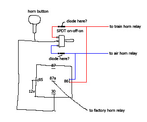
Train Horn Relay
› contactContact Us - Netstrata The first step towards benefiting from the Netstrata difference is to make an enquiry for an obligation free quote. Request a Quote. If you would like to visit us, scroll down to see our office locations.

automotive 4 pin and 5 pin RELAY EXPLAINED which one?
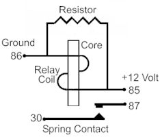
Steering Column Wiring Diagrams - Flaming River See below for an appropriate horn relay wiring diagram. 87a +12V +12V 30 86 85 87 Horn Button Ground Horn Relay Main Power Horn Relay Power P/N: 102569, Rev A . Notes If you need to record the pin-out or color scheme for the stock wire harness in your vehicle you can do so here: Function Wire Color Slot Horn Left Front Turn Signal Right Front Turn Signal Hazard …

M.N. Auto - Products
Zhejiang Meishuo Electric Technology Co.,Ltd 4 pin horn relay wiring MAH-124. Get more info. Electromagnetic Relay . Microwave Oven | Air Conditioning | Refrigerator 4 pin mini relay MPQ1-148D-B. 4 pole relay 24vdc MPF-S-124-A-5 pin 12 volt relay wiring MPJ2. 5 pin mini relay MPJ1-S-112-C. Get more info. Relay socket and harness. auto lighting|auto horn|auto air conditioner|automobile instrument 12v car …
Replacement 5-pin Relay For Air Horn Wiring Kits
5 Pin Horn Relay Wiring Diagram - Wiring Diagram 5 pin horn relay wiring diagram disclaimer. 4 or 5 pin relay with or without a diagram duration. Otherwise the structure wont function as it should be. Obd connector is meant to be used only by the service guy to monitor the health of your car and provide diagnosis. How to wire a 4 or 5 pin relay.

Used Japanese 12 volts heavy duty 4 pin relay with grip
FIAMM 12V 30A AMP 4 Pin Car Air Horn Relay | eBay 4 Pin Horn Relay - 12V - 30 Amp Made by Fiamm - Italy. 4 Pin Horn Relay - 12V - 30 Amp Made by Fiamm - Italy. ... FARBIN Air Horn Wiring Accessorie Car Horn Relay 12v 80a 4pin Spst Normally Open. $6.99. Free shipping Free shipping Free shipping. Sales Car Auto Automotive DC 12V 80A 80 AMP SPST Relay 4 Pin 4P Heavy Duty.
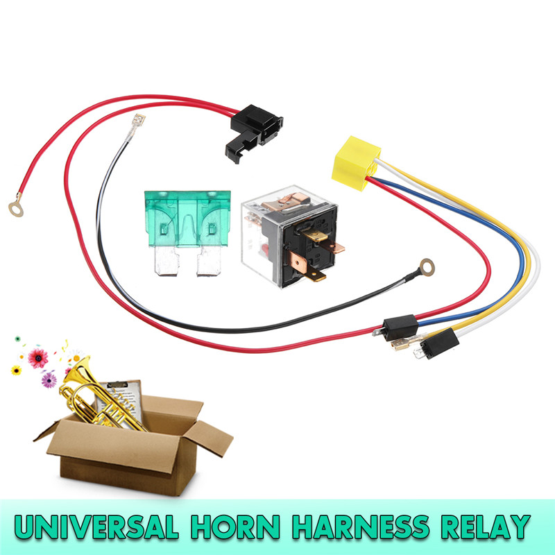
12V Universal Horn Wiring Harness Relay Kit Installation ...
Vixen Horn Relay Wiring Diagram - schematron.org 01.09.2018 01.09.2018 2 Comments on Vixen Horn Relay Wiring Diagram Free Shipping. Buy Vixen Horns 4-PIN Horn Relay 30A/12V with 4-PIN Pre-wired Quick Connect Relay Plug/Socket VXK at schematron.org Can be used with Horns, Power Trunk and many other applications (up to 30 amp circuits).
TheSamba.com :: Beetle - 1958-1967 - View topic - Horn Wiring
› hondaHONDA - Car PDF Manual, Wiring Diagram & Fault Codes DTC Kindly please help me with a complete wiring diagram for Alfa Romeo 155v6 2.5 167(AIC)..1995 to show the Bosch Motronic 88 pin outs and the location on the car of the ignition COTROL module.Thanks a mil and Happy New Year from Nairobi.
Lost...Horn Relay to Horn Wiring Help 69 B Body | For B ...
4 Pin Relay Wiring Diagram - Wiring Tech 4 Pin Relay Wiring Diagram October 23, 2021 It shows the components of the circuit as simplified shapes and. Wiring Diagram for A 4 Pin Relay wiring diagram is a simplified agreeable pictorial representation of an electrical circuit. 1974 Chrysler Starter Relay Wiring Diagram Electrical Circuit Diagram Electrical Diagram Trailer Wiring Diagram
Adding a new horn on W123 | Mercedes-Benz Forum
How to wire a 4 pin relay | Step-by-Step Guide The main difference between 4 pins and 5 pin relays is the number of circuits they can control at one time. Where 4 pins can control only one circuit, 5 Pin relay is capable of controlling power to more than one circuit at one time.  But, before we move on, do note that we can’t wire a 4 pin relay without knowing the applications. In ...
Adding Horn Relay - Need Help | Vintage Mustang Forums
How To Wire a 4 or 5 Pin Relay - YouTube In this video I show you how to wire a 12 volt automotive Bosch style relay. This video covers both 4 and 5 pin 12VDC relays.Best Connections - 12voltwire.co...

UNO MINDA 850038 Horn Relay - 4 Pin (Steel Body) - 12V DC
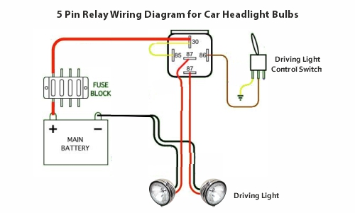
12V 4 Pin Relay Wiring Diagram Horn at Wiring Leave a reply cancel reply. In 12v 30a relay 4 pin wiring diagram, 12v 4 pin relay wiring diagram horn, 12v 40a relais 4 pin wiring diagram, 12v relay wiring diagram 5 pin for horn. So a single pole double throw has a mutual. For driving lights, you’ll have to connect the pin 30 of the relay to the 12v. Source: sfamuel.com

Ninja250 Riders Club :: Topic review - Questions about horn ...
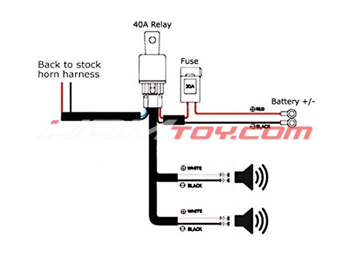
Wiring Diagram Horn Relay - Wiring Diagram Line Wiring Diagram Horn Relay Wiring Diagram Line Wiring Diagram. Wiring Diagram Line We are make source the schematics, wiring diagrams and technical photos ... 1971 corvette will inc guide kits instructions need electronic air install jeep wrangler 1pc universal 80a waterproof 4 pin lamp conditioner socket sho singapore harness kit ijdmtoy ...

Wiring new horn | Big Dog Motorcycles Forum
12v Relay Wiring Diagram 4 Pin - Wiring Space In 12v 30a relay 4 pin wiring diagram, 12v 4 pin relay wiring diagram horn, 12v 40a relais 4 pin wiring diagram, 12v relay wiring diagram 5 pin for horn. Leave a Reply Cancel reply. Your email address will not be published. Required fields are marked * Comment * Name * Email * Website.
wiring a horn relay 77 mgb : MGB & GT Forum : MG Experience ...
how to wire 4 pin relay - shapovmusic.com The difference between a 4 and 5 pin relay is that a 4 pin relay is used to control a single circuit, whereas a 5 pin relay switches power between two circuits. 4 pin relays use 2 pins (85 & 86) to control the coil and 2 pins (30 & 87) which switch power on a single circuit.
Boom blasters Wiring Horn Help - Ford F150 Forum - Community ...
2011-2012 Complete Wiring Diagram - Jeep Wrangler Forum 17.06.2020 · I came across this info on another site when I was looking for my 2012 stereo wiring diagram. Much more info than I needed but may be helpful to others. FYI the speaker wires were 100% accurate for my 2012 JK. Hopefully someone else finds this info useful too. If you read carefully almost all wires are identified for our 2011-2012's, not just stereo.
How to wire a relay for horns on MGB and other British cars ...
How To Wire A Relay For Horn & Lights With Diagram: 4 Pin Below is the step-by-step procedure of wiring the four-pin relay for the horn. Step 1. Connect The Relay's Coil Circuit Connect the coil circuit's terminal 86 to the battery positive power source. Connect the relay's coil circuit's terminal 85 to the steering wheel horn pad. Step 2. Connect The High Amperage Circuit Of Relay
relay diagrams | Pirate 4x4
Bulldog security 775 RELAY HOW IT WORKS: 775 RELAY to HORK HONK wire: 778 RELAY for TYPE C DOOR LOCKS Units without On Board Door Lock Relays: 778 RELAY for TYPE C DOOR LOCKS Reverse-Polarity, relays and harness: CHILD SAFETY LOCK diagram: CHRYSLER TRUNK RELEASE DIAGRAM (5-WIRE) DIODES and How They Work Page 1: DIODES and How They …

toyota horn wiring diagrams Questions & Answers (with ...
Horn Wiring | Car horn, Electrical diagram, Diagram 60 New 87a Relay Wiring Diagram They permit a small circuit to direct a innovative flow circuit using an electromagnet to rule the flow of electricity inside the circuit. They are usually labeled and identified on the mingle box panel. relay wiring diagram 87a visit the post for more 87a relay wiring diagram awesome 4 pin relay wiring diagram…
KTM 200 Duke - xBhp.com : The Global Indian Biking Community
4 Pin Relay Wiring Diagram Horn - autocardesign 4 Pin Relay Wiring Diagram Horn - wiring diagram is a simplified satisfactory pictorial representation of an electrical circuit. It shows the components of the circuit as simplified shapes, and the capability and signal contacts in the company of the devices.
Blaupunkt India
electrical - Wiring a 3 pin relay to power a dual horn ... I am trying to implement a dual horn setup for my bike. The stock came with a single horn. I have with me a 3-pin relay(H-B-S) with me. I am connecting the positive from the battery to the B terminal, Horns connected to the H terminal (horns are grounded on the other end).

Fiamm horn relay wiring | LaverdaForum
Trailer Wiring Diagram 4 Pin - Wiring Sample The most common 4 wire connector is the 4 pin flat connector as shown here. Can also be used as custom wiring on trailers with 3 light wire systems. 4 Pin Relay Wiring Diagram Lights Relay Car Horn Automotive Electrical . 4 pin connectors 4 pin connectors are the standard used for most trailers. Trailer wiring diagram 4 pin. Tail lights brake ...
Automotive Relay Diagram! 4 & 5 Pin Relay Wiring Diagram
4 Pin Relay Wiring Diagram Horn - easywiring connect a solderless ring terminal to one wire from the inline fuse holder and connect it to the positive terminal on the vehicle battery. 4 pin relay wiring diagram horn wiring diagram is a simplified satisfactory pictorial representation of an electrical circuit it shows the components of the circuit as simplified shapes and the capability and …
multiple horns with one switch
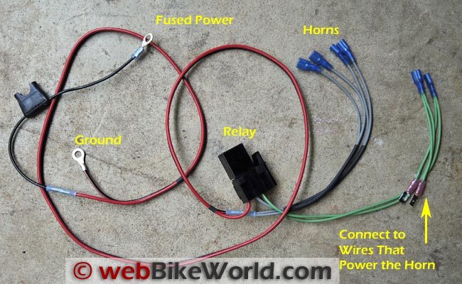
Dual Horn Relay Wiring Harness - webBikeWorld
Loud horns ! | Page 2 | Scion IQ Forums

12V Horn Wiring Harness Relay Kit For Grille Mount Blast Tone ...

Air horn installation, need help hooking up the wires | VW ...

5 Pin Relay With Diode Wiring Diagram ... | Electrical ...

How To Wire A Horn Relay? – Rx Mechanic
Hella horn relay wiring help/diagram ? | Page 2 | IH8MUD Forum
CAR HORN-HOW TO FIX-TEST-REPLACE-ADJUST AND MORE -
4 pin horn relay wiring MAH-124-A-1R_meishuoen

Denso Relay 4 Pin Wiring Diagram - Benign Blog
Bad Relay Found In KIA Car (Pride) | Electronics Repair And ...

horn upgrade - The International CBX Owners Association
Power Horns! - Page 111 - Team-BHP
12V Dual Tone Electric Air Horn Wiring Harness Relay For Car ...

How To Read Car Wiring Diagrams (Short Beginners Version ...

Electric Air Horn Relay Wiring Kit with Fuse Plug & Play Car MotorBike Truck 12V


Comments
Post a Comment