43 brayton cycle diagram
brayton | Editable Cycle Diagram Template on Creately A Cycle Diagram showing brayton. You can edit this Cycle Diagram using Creately diagramming tool and include in your report/presentation/website. Brayton Cycle Calculator - thermosolver.com Ideal Brayton Cycle consist of 4 steps: 1-2 Adiabatic Compression Process. 2-3 Isobaric Heat Addition Process. 3-4 Isentropic Expansion Process. 4-1 Isobaric Heat Rejection Process. The Schema of Brayton Cycle can be shown as: The Pressure-volume diagram of the Ideal Brayton Cycle is:
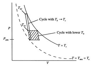
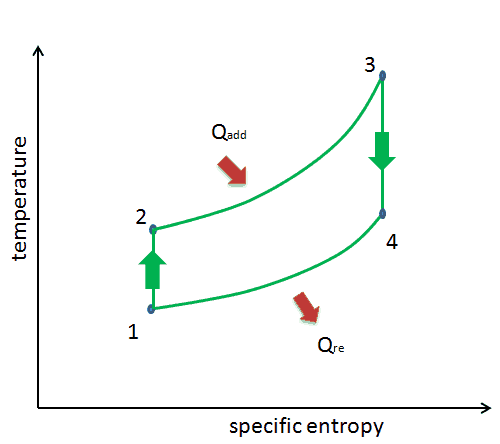
Brayton Cycle - pV - Ts Diagram - Nuclear Power Brayton Cycle - Ts diagram When plotted on a pressure-volume diagram, the isobaric processes follow the isobaric lines for the gas (the horizontal lines), adiabatic processes move between these horizontal lines, and the area bounded by the complete cycle path represents the total work that can be done during one cycle.

Brayton cycle diagram
Thermodynamics eBook: Brayton Cycle with Intercooling Brayton Cycle with Regeneration . T-s and P-v Diagrams of an Ideal Brayton Cycle with Regeneration Regenerator Saving Energy Input : In gas-turbine engines, if the temperature of the exhaust gases from the turbine is higher than the temperature of the air leaving the compressor, a counter-flow heat exchanger can be used to increase the temperature of the air by receiving heat from the ... Brayton Cycle - an overview | ScienceDirect Topics The Brayton cycle is represented on pressure-volume and temperature-entropy diagrams in Fig. 6. For this simple configuration the pressure ratio defined earlier represents the high pressure in the cycle divided by the low pressure in the cycle. Chapter 10: Refrigeration Cycles - Saylor Academy Chapter 10-5 The P-h diagram is another convenient diagram often used to illustrate the refrigeration cycle. The ordinary household refrigerator is a good example of the application of this cycle. Results of First and Second Law Analysis for Steady-Flow
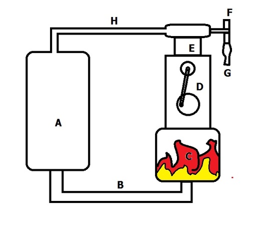
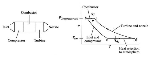
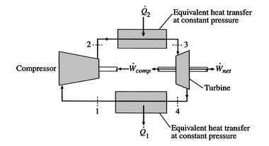
Brayton cycle diagram. Brayton cycle - SlideShare Brayton Cycle Brayton cycle is the ideal cycle for gas-turbine engines in which the working fluid undergoes a closed loop. That is the combustion and exhaust processes are modeled by constant-pressure heat addition and rejection, respectively. M. Bahrami ENSC 461 (S 11) Brayton Cycle 1 2. 3.7 Brayton Cycle - Massachusetts Institute of Technology The Brayton cycle (or Joule cycle) represents the operation of a gas turbine engine. The cycle consists of four processes, as shown in Figure 3.13alongside a sketch of an engine: a - b Adiabatic, quasi-static (or reversible) compression in the inlet and compressor; b - c Constant pressure fuel combustion (idealized as constant What is Brayton Cycle - pV - Ts Diagram - Definition Brayton Cycle - Ts diagram When plotted on a pressure volume diagram, the isobaric processes follow the isobaric lines for the gas (the horizontal lines), adiabatic processes move between these horizontal lines and the area bounded by the complete cycle path represents the total work that can be done during one cycle. What is Brayton Cycle - Gas Turbine Engine - Definition Brayton Cycle - Ts diagram When plotted on a pressure volume diagram, the isobaric processes follow the isobaric lines for the gas (the horizontal lines), adiabatic processes move between these horizontal lines and the area bounded by the complete cycle path represents the total work that can be done during one cycle.
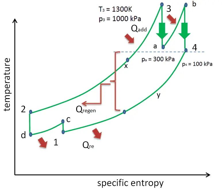
P-V and T-S Diagrams - NASA 13-05-2021 · The Carnot Cycle describes the operation of refrigerators, the Otto Cycle describes the operation of internal combustion engines, and the Brayton Cycle describes the operation of gas turbine engines. P-V and T-s diagrams are often used to visualize the processes in a thermodynamic cycle and help us better understand the thermodynamics of engines. PDF Regeneration Brayton cycle - irreversible Regeneration Brayton cycle - irreversible An actual gas turbine differs from the ideal due to inefficiencies in the turbines and compressors and pressure losses in the flow passages (heat exchangers in closed cycle). The T - s diagram may be as shown: static data for plot T-s diagram temperature 1200 1000 800 600 400 1 1.2 1.4 1.6 entropy PDF Brayton Cycle - Simon Fraser University The Brayton ideal cycle is made up of four internally reversible processes: 1-2 isentropic compression (in compressor) 2-3 const. pressure heat-addition (in combustion chamber) 3-4 isentropic expansion (in turbine) 4-1 const. pressure heat rejection (exhaust) Fig. 2: T-s and P-v diagrams for ideal Brayton cycle. Derive COP of Reversed Brayton Cycle, Diagram and Working ... Derive COP of Reversed Brayton Cycle, Diagram and Working of Reversed Brayton Cycle in Hindi🔥🔥SSC JE Test Series(Tech + Non Tech)- ...
Turbofan Explained- Thrust, Parts, T-S Diagram - LOFF Brayton Cycle T-S Diagram Brayton Cycle Efficiency Conclusion Thrust You need thrust to move forward! To propel! Thrust is a force, and force is a change of momentum. \vec {F} = m\vec {a}= \frac {d} {dt} (m\vec {v}) F = ma = dtd (mv), where m\vec {v} mv is a momentum. Brayton cycle - Wikipedia The Brayton cycle is a thermodynamic cycle that describes the operation of certain heat engines that have air or some other gas as their working fluid. The original Brayton engines used a piston compressor and piston expander, but modern gas turbine engines and airbreathing jet engines also follow the Brayton cycle. Although the cycle is usually run as an open system (and indeed must be run as ... Brayton Cycle - Gas Turbine Engine | Characteristics ... Brayton Cycle - Ts diagram When plotted on a pressure volume diagram, the isobaric processes follow the isobaric lines for the gas (the horizontal lines), adiabatic processes move between these horizontal lines and the area bounded by the complete cycle path represents the total work that can be done during one cycle. Turbine Engine Thermodynamic Cycle - Brayton Cycle The figure shows a T-s diagram of the Brayton cycle. Using the turbine engine station numbering system , we begin with free stream conditions at station 0 . In cruising flight, the inlet slows the air stream as it is brought to the compressor face at station 2 .
Ideal and real Brayton cycle. | Download Scientific Diagram
Brayton Cycle - Definition, Meaning, Efficiency, Ts, Pv ... Brayton cycle T-s diagram Process 1-2 Isentropic compression process In this process, the working gas is compressed adiabatically from state 1 to state 2 with the help of a compressor. The process is done by keeping the entropy constant and increasing its internal energy and internal pressure.
Brayton Cycle - Chemistry LibreTexts
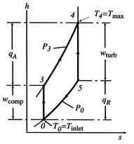
6.4 Brayton Cycle in - Coordinates 6. 4. 1 Net work per unit mass flow in a Brayton cycle In Section 3.7.1 we found the net work of a Brayton cycle in terms of heat transfer. Now that we have defined entropy, we can reexamine the net work using an enthalpy-entropy (-) diagram, Figure 6.6. The net mechanical work of the cycle is given by:

Brayton Cycle - an overview | ScienceDirect Topics
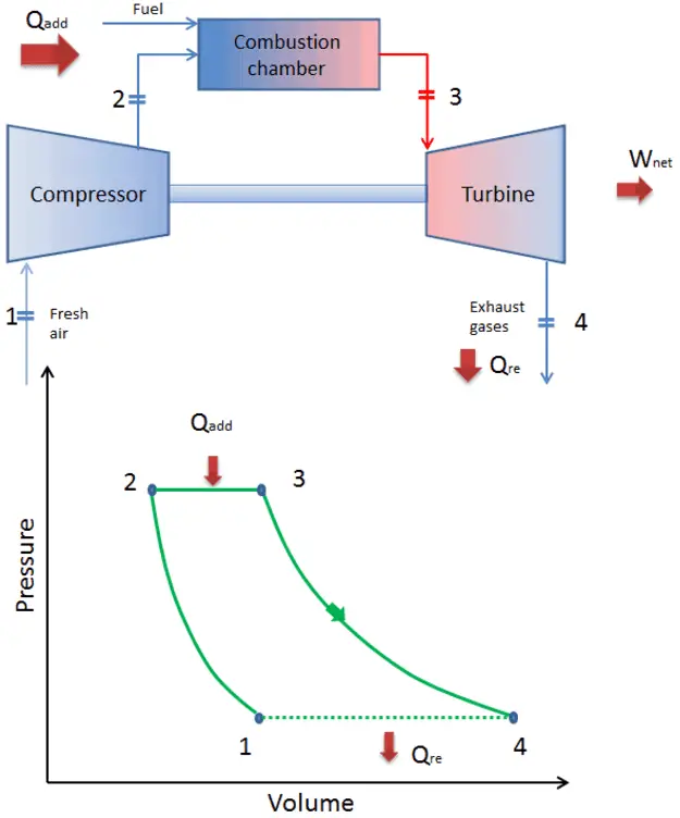
Thermodynamics eBook: Brayton Cycle The P-v and T-s diagrams of an ideal Brayton cycle are shown on the left. In an ideal Brayton cycle, heat is added to the cycle at a constant pressure process (process 2-3). q in = h 3 - h 2 = c P (T 3 - T 2) Heat is rejected at a constant pressure process (process 4 -1). q out = h 4 - h 1 = c P (T 4 - T 1)

Thermodynamics eBook: Brayton Cycle
Brayton cycle, Rankine Cycle, Otto Cycle - BrainKart BRAYTON CYCLE . The Brayton cycle is widely used as the basis for the operation of Gas turbine. A schematic diagram of a simple gas turbine (open cycle) and the corresponding p-v and T-s diagrams are shown below. Air is drawn from he atmosphere into compressor, where it is compressed reversibly and adiabatically.

Temperature versus Entropy Diagram for Ideal Brayton Cycle ...
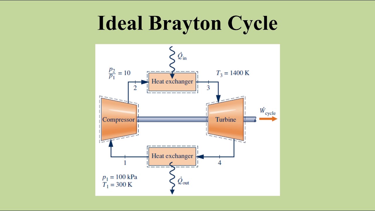
Brayton Cycle Experiment Jet Engine | Turbine Engine ... A schematic of the Brayton (simple gas turbine) cycle is given in Figure 1. Low-pressure air is drawn into a compressor (state 1) where it is compressed to a higher pressure (state 2). Fuel is added to the compressed air and the mixture is burnt in a combustion chamber. The resulting hot gases enter the turbine (state 3) and expand to state 4.
3.7 Brayton Cycle
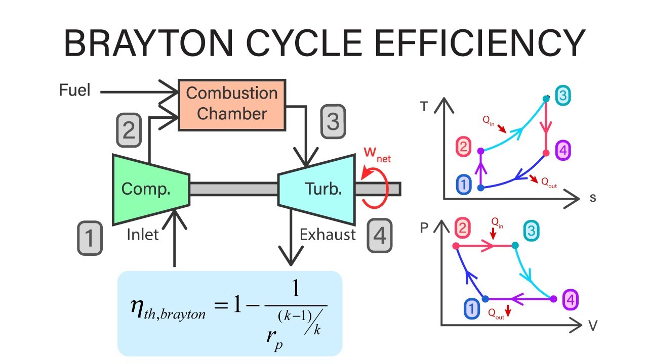
Brayton Cycle | Efficiency, P-V & T-S Diagrams | Heat ... Brayton cycle (or Joule Cycle) is a thermodynamic cycle upon which a Gas turbine works. Gas turbines are used to generate power at many places. Brayton cycle is named after George Brayton, an American engineer who developed it. Below are P-V and T-S Diagrams of the Brayton (or Joule) Cycle. Brayton Cycle is comprised of four processes Process 1-2

EFFECT OF INTERCOOLING ON BRAYTON CYCLE - UNDERSTANDING ...
Brayton Cycle | How does Brayton Cycle work? | Mechanical ... Brayton Cycle PV diagram Isentropic compression: Firstly, the gas is sucked from the atmosphere to the engine combustion chamber. As the working gas (such as helium) is sucked, the compressor compresses it in such a way that there is no change in heat.

Brayton Cycle (Gas Turbine) - MATLAB & Simulink
Brayton Cycle - Mechanical Education The Brayton cycle is also called a joule cycle. Brayton cycle is applied in the Gas turbines. A gas turbine is used in power plants for generating power and a gas turbine is also used in aircraft engines. A gas turbine is the best example to understand the complete process of the Brayton cycle. P-V Diagram of a Brayton Cycle:

Brayton Cycle | How does Brayton Cycle work? | Mechanical Boost
Four-Stroke Cycle - an overview | ScienceDirect Topics In four-stroke cycle engines, both SI and CI, there are four strokes completing two rotations of the crankshaft. These are respectively the suction or charging, compression, power/work or expansion, and exhaust strokes. The important variable characterizing operational conditions in each engine is the brake mean effective pressure (b MEP), which is the mean effective …

Brayton cycle - Wikiwand
Turbine Engine Thermodynamic Cycle - Brayton Cycle The figure shows a T-s diagram of the Brayton cycle. Using the turbine engine station numbering system , we begin with free stream conditions at station 0 . In cruising flight, the inlet slows the air stream as it is brought to the compressor face at station 2 .

Brayton Cycle – Definition, Meaning, Efficiency, Ts, Pv ...
Air standard Brayton cycle - IIT Kanpur The pressure ratio of the Brayton cycle, r p is defined as, Then The processes 1-2 and 3-4 are isentropic. Hence, We get, or Work delivered by the cycle is given by W= h Q 1 . Increasing Q 1 can increase work done by the cycle . Since the Turbine blade material cannot withstand very high temperature, T 3 and hence Q 1 is limited

Brayton cycle - Wikipedia
Pressure volume diagram - Energy Education The PV diagram models the relationship between pressure (P) and volume (V) for an ideal gas.An ideal gas is one that never condenses regardless of the various changes its state variables (pressure, volume, temperature) undergo. In addition, the processes plotted on PV diagrams only work for a closed system (in this case the ideal gas), so there is no exchange of …

Closed-Loop Brayton Cycle - an overview | ScienceDirect Topics
Gas Brayton Cycle - an overview | ScienceDirect Topics The ideal gas Brayton cycle (1876, and also proposed by Joule in 1851), shown in graphic form in Fig. 4A as a pressure-volume diagram, is an idealized representation of the properties of a fixed mass of gas (working fluid) as it passes through a gas turbine in operation (Fig. 4B).

File:Brayton Cycle TS Afterburner.svg - Wikimedia Commons
PDF Brayton Cycle - University of Waterloo Brayton Cycle Reading Problems 9-8 → 9-10 9-78, 9-84, 9-108 Open Cycle Gas Turbine Engines • after compression, air enters a combustion chamber into which fuel is injected • the resulting products of combustion expand and drive the turbine • combustion products are discharged to the atmosphere • compressor power requirements vary from 40-80% of the power output of the turbine (re-
3.7 Brayton Cycle
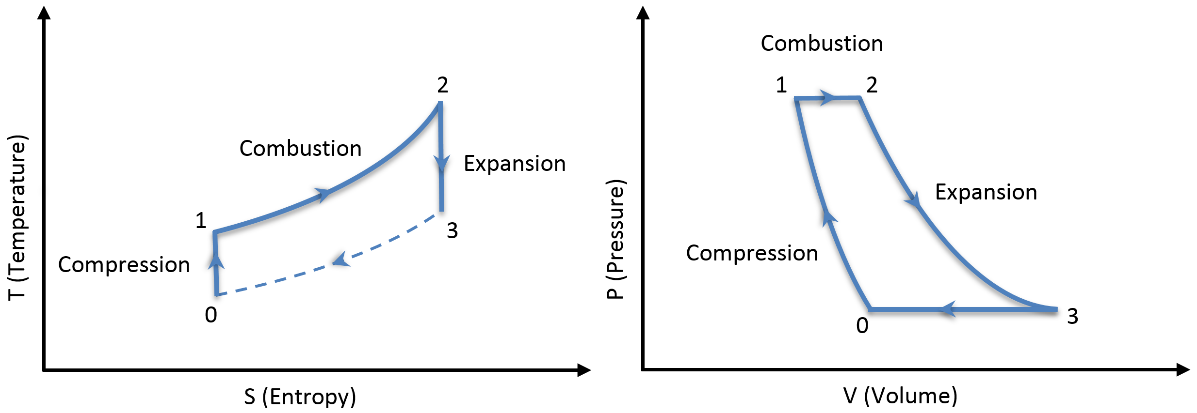
Brayton Cycle - Chemistry LibreTexts 15-08-2020 · The Brayton Cycle can then be described quantitatively in the gas turbine engine of a jet by two diagrams, the Temperature/Entropy Diagram and the Pressure/Volume Diagram. Temperature/Entropy Diagram In this diagram, we see that there are 8 processses to describe the Brayton cycle in terms of temperature, entropy, and pressure.
Air standard Brayton cycle
PV and TS diagram of Brayton Cycle Gas Turbine - YouTube Learn how to draw the PV and TS diagram of Brayton Cycle

Applications - The Brayton Cycle
Chapter 10: Refrigeration Cycles - Saylor Academy Chapter 10-5 The P-h diagram is another convenient diagram often used to illustrate the refrigeration cycle. The ordinary household refrigerator is a good example of the application of this cycle. Results of First and Second Law Analysis for Steady-Flow

Process flow diagram of a Brayton gas power cycle with ...
Brayton Cycle - an overview | ScienceDirect Topics The Brayton cycle is represented on pressure-volume and temperature-entropy diagrams in Fig. 6. For this simple configuration the pressure ratio defined earlier represents the high pressure in the cycle divided by the low pressure in the cycle.
Brayton Cycle - pV - Ts Diagram
Thermodynamics eBook: Brayton Cycle with Intercooling Brayton Cycle with Regeneration . T-s and P-v Diagrams of an Ideal Brayton Cycle with Regeneration Regenerator Saving Energy Input : In gas-turbine engines, if the temperature of the exhaust gases from the turbine is higher than the temperature of the air leaving the compressor, a counter-flow heat exchanger can be used to increase the temperature of the air by receiving heat from the ...
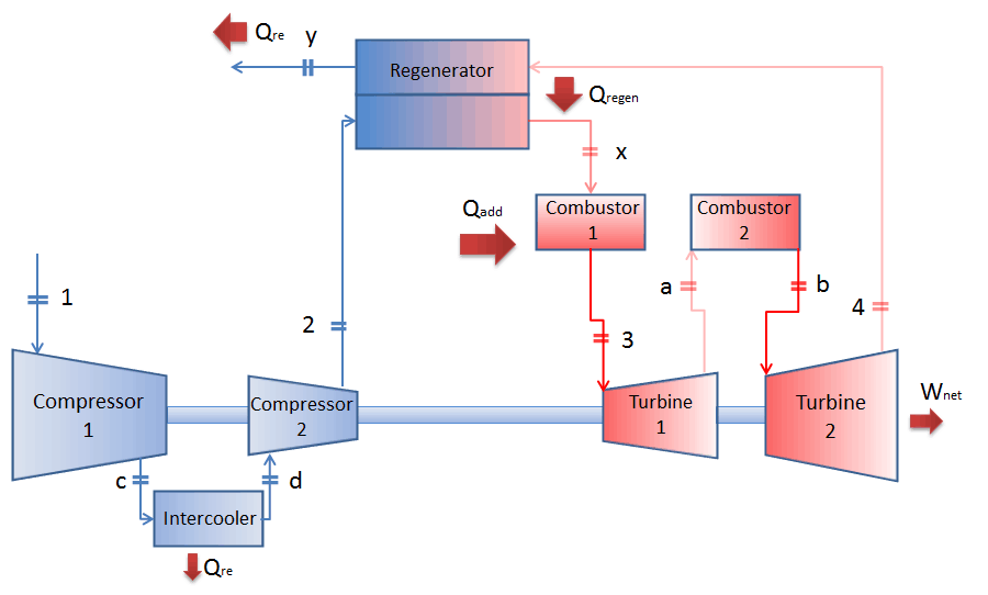
Brayton Cycle with Reheat, Regeneration and Intercooling
Turbine Engine Thermodynamic Cycle - Brayton Cycle

Brayton Cycle Calculator

Brayton cycle - Wikipedia

Thermodynamics eBook: Brayton Cycle

Brayton Cycle | How does Brayton Cycle work? | Mechanical Boost
Mechanical Engineering Thermodynamics - Lec 17, pt 2 of 5: Brayton Cycle Efficiency

Jet Propulsion/Thermodynamic Cycles/Brayton cycle - Wikibooks ...
3.7 Brayton Cycle
Brayton Cycle - pV - Ts Diagram
Brayton Cycle - pV - Ts Diagram

Brayton cycle - ASCEND

Figure 3. T-S diagram of Brayton Cycle (Ogbonnaya, 2004b ...

2: T-s diagram showing a non-ideal Joule-Brayton cycle during ...

What is the Brayton cycle? - ExtruDesign

BRAYTON CYCLE WITH REHEATING - UNDERSTANDING BUSINESS ...
How does a jet engine work? Brayton thermodynamic cycle and ...

Simple Brayton gas cycle. (a) Component of cycle. (b) (T-S ...
Ideal Brayton Cycle (Air-Standard and Cold Air-Standard)

Efficiency of an Ideal Brayton Cycle with a Constant-Volume ...

Boiler and Turbine: The Brayton Cycle
6.4 Brayton Cycle in - Coordinates

Brayton Cycle - Thermodynamics Cycle

P-V diagram of Brayton cycle. | Download Scientific Diagram


Comments
Post a Comment