43 hydraulic spool valve diagram
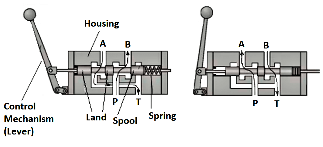
HYDRAULIC SPOOL VALVE GEROLER MOTOR | Manualzz 8490393 11.9 cu. in. 2-Bolt Hydraulic Spool Valve Geroler Motor V 3.04. Visit for more information 3. 8490393 11.9 cu. in. 2-Bolt Hydraulic Spool Valve Geroler Motor V 3.04. Removing screws and bolts. The screws are held in place with cyanoacrylate glue or instant... PDF Hydraulic / pneumatic valves 1 Hydraulic valves are made to a high standard of quality and robustness. The diagram shows a few of the vast range of hydraulic valves available. 3. OTHER DESIGNS. POPPET VALVES The directional control valves so far studied are all of the type that uses a sliding piston or spool.
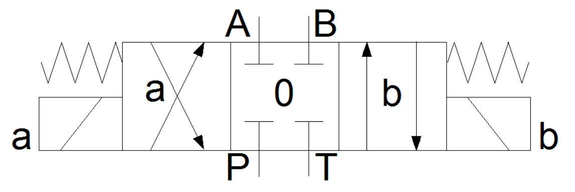
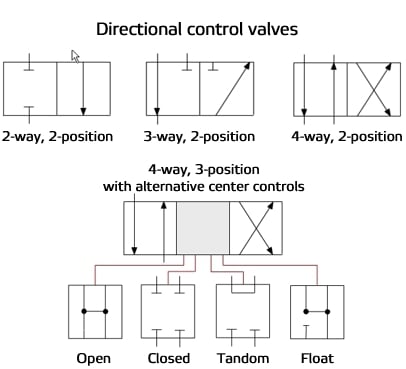
How to read hydraulic circuits, schematic hydraulic symbols to DIN... Hydraulics schematic symbols are a basic component of hydraulic circuit. If the lines intersect in the diagram but are not connected, then an arc is drawn at the intersection point. To denote a directional valve, several squares are drawn. Each square symbolizes 1 position of the spool.

Hydraulic spool valve diagram
PDF Hydraulic circuit diagram showing basic functions, standard valve Valve housing inclusive of spool, pressure relief valve etc; but exclusive of spool actuators. Conventional inlet (I). The circuit diagram above shows the F130CF with three spool sections and a mid-inlet between sections 2 and 3. The shaded areas indicate functions or function groups that are... PDF Spool Valves FEATURES • All the exhaust ports of the spool valve are connectable, providing better environmental protection. Particularly recommended for sensitive areas, such as clean rooms, and applications in the pharmaceutical and food processing sectors • The valves offer environmental protection against the... PDF Directional spool valves, direct operated, with solenoid actuation The directional valves of type WE are solenoid-actuated directional spool valves that can be used as electro-magnetic component. - Dependent on the hydraulic fluid used, the maximum ambient and hydraulic fluid temperature Top view. Directional spool valve | WE 25/28. Circuit diagram 1+ 4-.
Hydraulic spool valve diagram. Hydraulic Actuator : Working, Types, Advantages & Its ... The schematic diagram of the hydraulic actuator system is shown below. Hydraulic Actuator Working. This system mainly uses Pascal’s Law, which states that when the pressure is applied at a particular point to a limited fluid within a container then it transmits evenly in all the ways within the liquid & the container’s walls without any loss. If pressure (P) is applied to an area (A), then ... PDF Hydraulic Variable Valve Timing Spool Valve Spool Valve Housing. 3. Input Shaft. Figure 18 Rotary Valve Section View [2]. 1. In M.W.H. Bergmans design the PX20 Expansion Box. Figure 31 Test Bench Electrical Diagram. All controllable input or output devices that are required to both ensure the proper operation of the... PDF Hydraulic operated directional valves Hydraulic operated directional valves are spool type, three or four way, two or three position, designed to operate Available with single or double hydraulic actuator. Valve sizes and max flow: DH-0 = size 06, flow up to See note and diagrams on table E010 relating the DH* valve from which DH-0* are... PDF Spool valve hydraulic motors Hydraulic motors. Application calculation. Warranty. Final. Spool valve hydraulic motors. The function diagrams data is for average performance of randomly selected motors at back pressure 5÷10 bar [72.5÷145 PSI] and oil with viscosity of 32 mm²/s [150...
PDF Directional control valves These valves can be actuated by solenoid, hydraulic or pneumatic pilot, lever, or mechanically. These manual valves are available with a choice of up to nine different spool types, depending on Please note that European designations are the opposite. See diagram on the nameplate of the... Basic Hydraulic System - Components / Parts,Design & Circuit Diagram Hydraulic system components are hydraulic pump,hydraulic motor/ hydraulic cylinder, pressure control valve,directional control valve,flow control I. Pressure Relief Valve - They are designed to protect hydraulic system when pressure in the system increases beyond the specified design... PDF Untitled | Hydraulic diagram - Spool-type valves - Valves with calibrated ports. - Equipment running at low working pressure - Pilot plants and equipment - Equipment with low frequency cycles. PRESSURE REDUCING VALVES Index. Hydraulic diagram. Type VRPRL/U... Description. The Basics Of Hydraulic Spool Valves - CrossCo A directional valve with the same size body - same size ports - same electrical connections - can do a variety of different functions and all you need to do is change the spool! Externally, the valve will look exactly the same but internally the flow paths may be completely different. They all look the same but...
PDF Hydraulic Screw-in Cartridge Valves (SiCV) The valve can be used as a priority flow regulator, with regulated flow being supplied to port 3 and excess flow being by-passed to port 2. If port 2 The PAR1-10 is an electric, proportionally controlled, internally pilot operated, spool type screw-in relief valve. It is capable of handling flows from 3,8-60,0... What is a Spool Valve and How Does it Work? | RealPars Learn about pneumatic and hydraulic spool valves in this short yet informative blog post by RealPars experts! Spool valves can be used in both hydraulics (where the oil is the energy source) or Pneumatics (where the air is the energy source) and their job is to control the flow direction of the... Fluid Power Systems | Hydraulic System... | Instrumentation Tools A "spool" valve is a special type of flow-directing valve used in pneumatic and hydraulic systems to direct the pressurized fluid to different locations. Note that the boxes in a spool valve symbol are never shifted or grayed-out in color like this to represent the valve's state in a real fluid power diagram. Spool Valves Spool-type valves are widely used because they can be shifted to two, three, or more positions for routing fluid between different combinations of inlet and outlet ports. 3. Arranging binary valves into a hydraulic integrated circuit allows them to accomplish the same functions as discrete spool-type...
Four Way Directional Control Valves or "Which Way Will the ...
Guide to Hydraulic Spool Valve Adjustment - Global Electronic Services Hydraulic spool valve operation requires repairs and troubleshooting procedures not used for other types of devices. To avoid costly replacements that could eat into a company's profits, floor managers must understand how these valves work and recognize signs that they need adjustments or other...

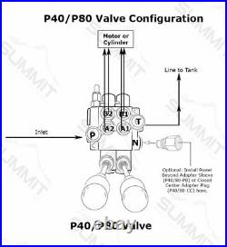
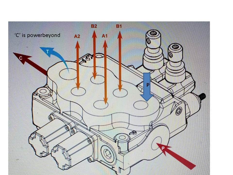
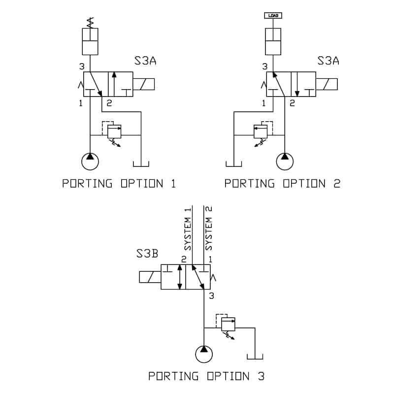
How to configure mobile hydraulic valves using power beyond
Directional control valve - Wikipedia Directional control valves (DCVs) are one of the most fundamental parts of hydraulic and pneumatic systems. DCVs allow fluid flow (hydraulic oil, water or air) into different paths from one or more sources.

Highway hydraulics flow control | Screw-in cartridge valves ...
Hydraulic Spool Valve Diagram | Hydraulic Valves Spool Diagram Hydraulic spool valve diagram about the different spools function in hydraulic directional valves. Better knowing its symbol before selection valve spools. The hydraulic spool valves target is to reach different mechanical movement of actuator, like to release pressure, stop or redirect the...

Log Splitter Valve and Accessories by Energy® Manufacturing ...
Mechanical Engineering | Pneumatic 5-ported 3-position valve... [Directional control valve. Wikipedia] The Mac template "Pneumatic 5-ported 3-position valve" for the This hydraulic schematic example was redrawn using ConceptDraw PRO diagramming and Sliding the spool to one side routes the hydraulic fluid to an actuator and provides a return path from...

How to Read a Spool Valve Schematic Drawing - RealPars
What is a Spool Valve? - YouTube What is a Spool Valve? Смотреть позже. Поделиться.

How to configure mobile hydraulic valves using power beyond
PDF Hydraulics, Basic Level (Textbook) | 12. Flow control valves These valves control the direction of flow of the hydraulic fluid and, thus, the direction of motion and the positioning of the working components. Shut-off valves are shown in circuit diagrams as two triangles facing one another. They are used to depressurise the systems manually or to relieve...

Rexroth 4WMM16 Directional Spool Valve from China ...
Directional spool valve 1 Drawing: valve body + spool. Download scientific diagram | Directional spool valve 1 Drawing: valve body + spool. from publication: Numerical and experimental investigation for the design of a directional Hydraulic valves are one of the most studied component in the fluid power field since they control the flow in complex systems.

Hydraulic Sliding-Spool Valve - Hydraulic & Process Valve
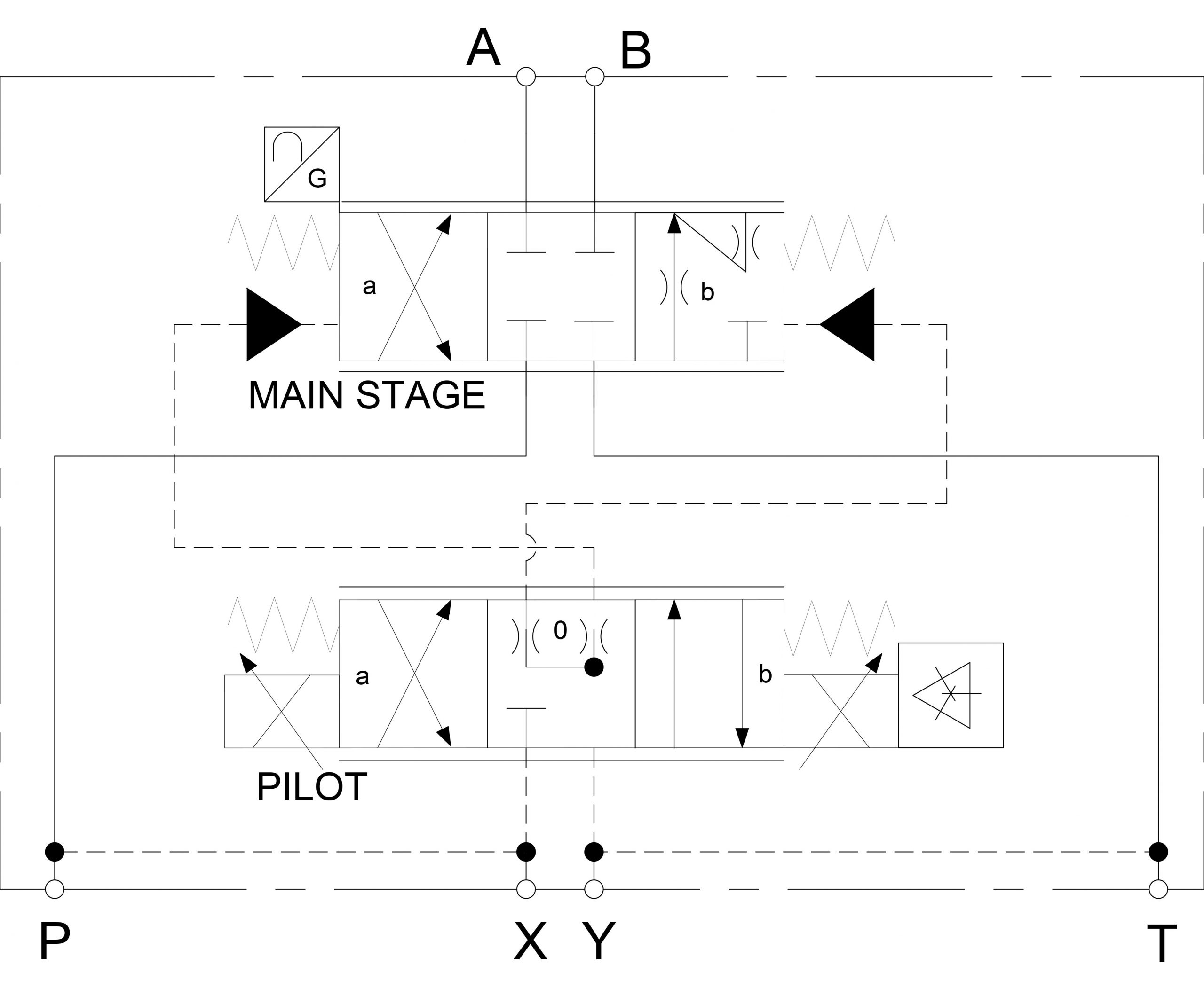
PDF Robust -Controller for Hydraulic Spool Valve, Pilot Operated with... Keywords: electro-hydraulic spool valve; robust control; micro valves; uncertain system identification. block according to the presented hydraulic diagram. To investigate the dynamics of the valve block, and its sensitivity to the various constructive parameters, we relied on the...

WE6, WE10 Solenoid Operated, Hydraulic Directional Spool Valve
PDF Proportional directional spool valve type The directional spool valves types PSL and PSV serve to control both, the direction of movement and the load-inde-pendent, stepless velocity of the hydraulic consumers. The proportional spool valves of this pamphlet are designed as valve banks and consist of three functional groups: Basic data Design.

How to Read a Spool Valve Schematic Drawing - RealPars
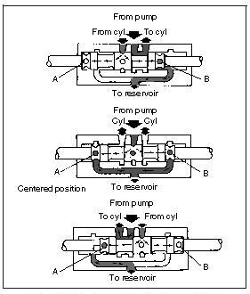
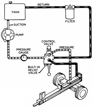
Microsoft Word - Hydraulic Systems Basics.doc | Control Valve The spool valve has the capability to direct fluid flow to either end of the actuator. Accurate diagrams of hydraulic circuits are essential to the technician who must diagnose and repair possible problems. The diagram shows how the components will interact.
![PDF] Modelling of Hydraulic Spool-Valves with Specially ...](https://d3i71xaburhd42.cloudfront.net/3af4699bb0da814a957c00f6f173debd7a8f83ac/2-Figure1-1.png)
PDF] Modelling of Hydraulic Spool-Valves with Specially ...
PDF Directional spool valves, pilot-operated, with hydraulic or... Directional spool valve | WEH; WH 7/40. Symbols for valves with 2 spool positions. Valve with spring end position. Any; horizontal with valves with hydraulic control spool return "H" and symbol A, B, C, D, K, Z, Y. With suspended installation, higher sensitivity to contamination - horizontal is...

Directional Control Valve Basics - Part 1
PDF Accessories • Function Pressure-control valves are used in hydraulic systems to control actuator force (force In spool position as shown in figure-A, there is connection from P to A and B to T. Fluid flows form • Schematic diagram of non-pressure-compensated needle-type flow-control valve is shown in Fig.

Spool Valve - an overview | ScienceDirect Topics
PDF Fluid Power Engineering | 4 Hydraulic Pumps 5.3.5 Flow Characteristics of Spool Valves. 5.3.6 Pressure and Power Losses in the Spool Valves. 5.3.7 Flow Forces Acting on the Spool. Calculate all of the system operating parameters at this mode. Neglect the hydraulic losses in the system elements, except for the throttle valve.

Hydraulic Switching Valves | SpringerLink
PDF Directional spool valves, direct operated, with solenoid actuation The directional valves of type WE are solenoid-actuated directional spool valves that can be used as electro-magnetic component. - Dependent on the hydraulic fluid used, the maximum ambient and hydraulic fluid temperature Top view. Directional spool valve | WE 25/28. Circuit diagram 1+ 4-.
What is a Spool Valve? - Types, Configurations, Applications
PDF Spool Valves FEATURES • All the exhaust ports of the spool valve are connectable, providing better environmental protection. Particularly recommended for sensitive areas, such as clean rooms, and applications in the pharmaceutical and food processing sectors • The valves offer environmental protection against the...
Hydraulic symbology 302 – high response valves
PDF Hydraulic circuit diagram showing basic functions, standard valve Valve housing inclusive of spool, pressure relief valve etc; but exclusive of spool actuators. Conventional inlet (I). The circuit diagram above shows the F130CF with three spool sections and a mid-inlet between sections 2 and 3. The shaded areas indicate functions or function groups that are...

HOW TO READ A SPOOL VALVE SCHEMATIC DRAWING

The Basics Of Hydraulic Spool Valves - CrossCo
Hydraulic Symbology 201 – industrial directional valves

BOOK 2, CHAPTER 8: Directional Control Valves | Power & Motion
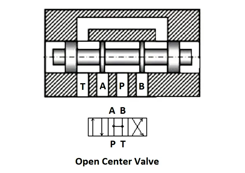
Open Center Sliding Spool Directional Control Valve ...
Reading fluids circuit diagrams - hydraulic & pneumatic symbols

What is a Spool Valve and How Does it Work? | RealPars

a) Schematic of the main-stage valve spool with actuator ...

Basic Hydraulics - Directional Control Valve - Blog.Teknisi
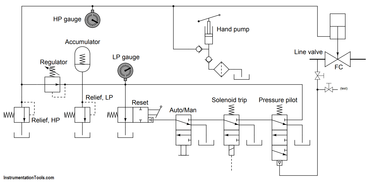
Hydraulics Systems Diagrams and Formulas | Cross Mfg.

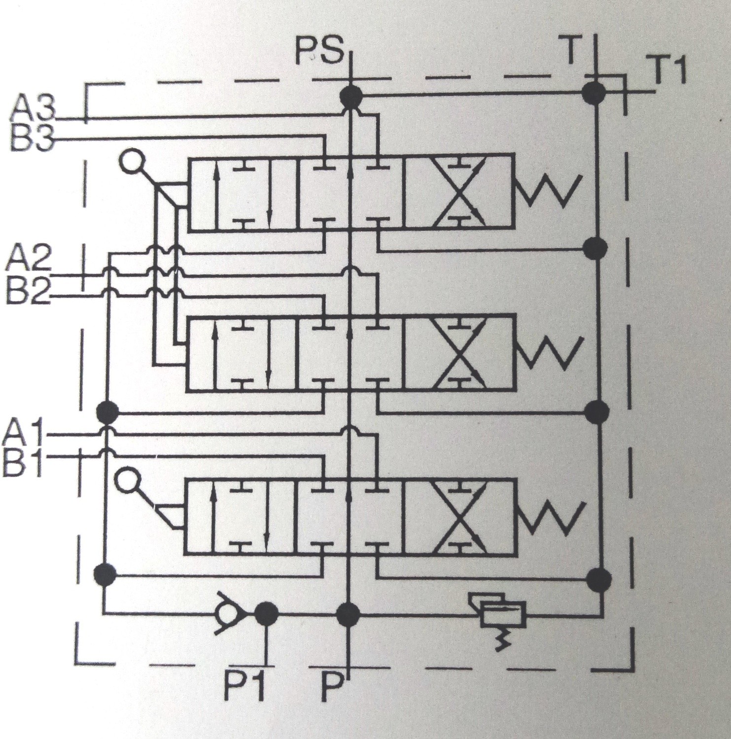
Hydraulic Monoblock Solenoid Directional Control Valve, 6 Spool, 13 GPM
14 | March | 2021 | Hydraulic Valve Direction
Hydraulic Flow Control 5 Spool Valve 3/8" BSP Ports

Hydraulic Solenoid Valve - How They Work | Tameson.com
What is a Spool Valve? - Types, Configurations, Applications

How to configure mobile hydraulic valves using power beyond
3W2P Spool Valves • Related Fluid Power

Buy Monoblock Hydraulic Directional Control Valve, 3 Spool ...
WK 421 610 Directional spool valve type UREP10 electro ...
Identify all Spool Valve Positions - InstrumentationTools

CHAPTER 10: Directional Control Valves, part 4 | Power & Motion

Commande De Direction Hydraulique Du Tracteur Valve Chargeur ...
Hydraulic Flow Control Valve 1/2" BSP Ports 2 Spool

Spool Valve - an overview | ScienceDirect Topics

Hydraulic Control of Actuators (Automobile)

Distributeur monobloc commande manuelle et électrique 12v 50 l/min 1 x double effet - Hydrulic Master Online shop

Model view of the spool valve with used notation. | Download ...


Comments
Post a Comment