43 pneumatic circuit diagram
Pneumatic circuit diagrams - Learnchannel-TV.com In pneumatic circuit diagrams, the components are arranged the way that the flow of energy always flows from the bottom up (as opposed to electrical ... Basic pneumatic circuit - SlideShare Basic pneumatic circuit 1. ... Circuit layout The standard for circuit diagrams is ISO 1219-2 A4 format or A3 folded to A4 height for inclusion in a manual with other A4 documentation To be on several sheets if necessary with line identification code Minimum crossing lines Limit valves position of operation by actuators shown by a marker with ...
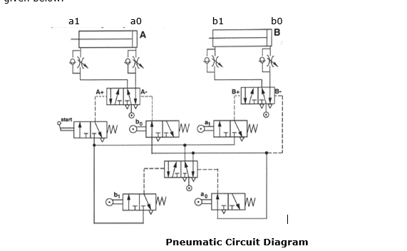
Pneumatic circuit diagrams - Learnchannel-TV.com In pneumatic circuit diagrams, the components are arranged the way that the flow of energy always flows from the bottom up (as opposed to electrical schematics). Thus the pressure source represents the first element, the actuator, the last element. In purely pneumatic circuits the processing of the input signals is also performed pneumatically.
Pneumatic circuit diagram
FREE Fluid Power schematic design software - FluidPower.Pro A pneumatic circuit diagram can be easily created by using the database for pneumatic equipment drawing symbols. SMCDraw screenshot. Benefits: Some simple calculation can be made after system design (full stroke time, max velocity, flow, Dynamic characteristics simulation, etc.). PDF Pneumatic Control Schematics - Velvac Pneumatic Control Schematics • Applications shown in the document are: Lift axle circuits, suspension dump circuits and tailgate control circuits for single acting air cylinders. (Air to open spring to close) Single acting air cylinders require what is known as a 3 way valve function. Because Velvac valves are multi-purpose we can Reading fluids circuit diagrams - pneumatic circuit examples October 1, 2021 - This article describes two example pneumatic schematic diagrams: winder lowering cradle safety pins and winder belted threader operation.
Pneumatic circuit diagram. Pneumatic Circuit Diagram | Products & Suppliers ... Description: ISO 1219-2:2011 establishes the main rules for drawing hydraulic and pneumatic circuit diagrams using graphical symbols drawn in accordance with ISO 1219-1. ISO 1219-2:2011 also applies to circuit diagrams relating to cooling systems, lubrication systems, cooling. Description: , or as an ON-OFF valve. Pneumatic circuits - Fluid power - Uni Siegen - StuDocu Differentiate between pneumatic circuit and pneumatic circuit diagram State basic rules used in design of pneumatic circuits Explain the memory, delay, OR , AND and NOT functions Explain the direct and indirect control of single acting cylinder Explain the direct and indirect control of double ... 4 Basic Pneumatic Circuits | Power & Motion Pneumatic components can be combined to cycle automatically without external controls (see schematic below). It shows compressed air controlled by three valves (VLV05, VLV07 and VLV08). And when the solenoid (SOL06) is energized while the cylinder (CYL03) is retracted, the system starts cycling to extend and retract the cylinder. PDF Pneumatic Symbols - Norgren Pneumatic Symbols DIRECTIONAL CONTROL VALVES PROCESS VALVES DESCRIPTION IMAGE DESCRIPTION IMAGE 2/2- way valve, air operated, NC Angle valve, 2-way 2/2- way valve, direct operated, NC Ball valve, 2- way 2/2- way valve, pilot operated, NC Ball valve, 3- way, L 3/2- way valve, air operated, NC Ball valve, 3- way, T
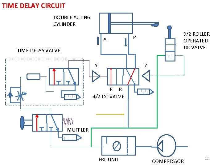
Create a pneumatic or hydraulic control system diagram Less. Create fluid power diagrams in Visio Professional or Visio Plan 2 to document hydraulic or pneumatic control systems, such as those used in factory automation systems, heavy machinery, or automobile suspension systems. In Visio 2016 and newer versions: Click Templates > Engineering > Fluid Power > Create. Create a Pneumatic Circuit Diagram using SMC Draw #1 - YouTube How to Create a Pneumatic Circuit Sketch using SMC Draw (Great Free Software available online) - 3/2 push button control of single acting cylinder PDF A Regulator in a Circuit Pneumatic Circuits - Parker Hannifin Pneumatic Circuits Pneumatic Flow Control Problems In applications, any of the pneumatic controls discussed above may present an objectionable "jump" or rapid partial stroking of the cylinder. This condition may occur when initiating cylinder motion at any position. Supply pressure pushes the piston, which in turn must push out the exhaust air. PDF Pneumatics Basic Level - Festo Didactic Drawing of pneumatic circuit diagrams in accordance with standards Representation of motion sequences and operating statuses Direct and indirect stroke-dependent controls AND/OR logic functions of the input signals Time-dependent control system with time-delay valve
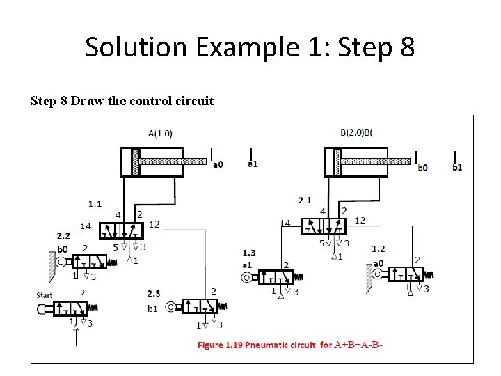
Design aids for pneumatics - Design World Pneumatic circuit diagrams and parts lists can also be quickly created on a PC. The comprehensive FluidDRAW symbols library accesses the extensive integrated library of DIN standard pneumatic symbols. These are arranged into groups according to drives, valves, valve terminals, compressed air preparation, vacuum technology, flow control and non ... Pneumatic circuits - SlideShare Pneumatic circuits 1. Basic Pneumatic Circuitry For control and automation 2. Contents Introduction Symbols Circuit layout Actuator control 2/2 Valve Actuator control 3/2 Valve Actuator control 5/2 Valve Sequential control Sequence solution 5/3 Valves Poppet/spool logic Balanced spool logic Feedback Click the section to advance directly to it Hydraulic and Pneumatic P&ID Diagrams and ... - Inst Tools Figure 31 shows the system represented in Figure 30 in cutaway diagram format and illustrates the similarities and differences between the two types of diagrams. Figure 31 Cutaway Fluid Power Diagram. A schematic diagram uses symbols to show the elements in a system. Schematics are designed to supply the functional information of the system. Module 5 Pneumatic control circuits.pdf - MODULE 5 ... DEPT OF ME GAT 2 MODULE 5 PNEUMATIC CONTROL CIRCUITS Large cylinders as well as cylinders operating at high speed are generally actuated indirectly as the final control valve is required to handle large quantity of air. In the case of pilot operated valves, a signal input valve [3/2 way N.C type, 1S1] either actuated manually or mechanically is used to generate the pilot signal for the final ...
Electropneumatics – Learnchannel-TV.com
Pneumatic circuit - Wikipedia A pneumatic circuit is an interconnected set of components that convert compressed gas (usually air) into mechanical work. In the normal sense of the term, the circuit must include a compressor or compressor-fed tank. Components. The circuit comprises the following components: Active components ...

Reading fluids circuit diagrams - pneumatic circuit examples
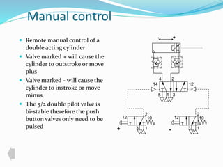
PDF Reading Pneumatic Schematic Symbols - Gears EdS Reading Pneumatic Schematic Symbols A B EA P EB 5/2 Valve has 5 ports and 2 possible conditions 1.) B is pressurized and A is exhausted. 2.) A is pressurized and B is exhausted. When the solenoid is NOT energized the B port is pressurized. The spring symbol defines the valve position at rest. The Return Spring
Basic pneumatic circuit
Pneumatic circuits drawing PneuDraw allows you to draw pneumatic circuits quickly and easily. With the new online release, it is easier than never to draw your circuits. Beside pneumatic symbols the tool includes generic symbols as well as special symbols to design business processes and flow diagrams.
4 Basic Pneumatic Circuits | Power & Motion
PDF Introduction to Pneumatics - Philadelphia University Schematic Diagram of a Pneumatic Circuit. Figure 1-21. Connection Diagram of a Pneumatic Circuit. G 4. On the Conditioning Unit, open the main shutoff valve and the branch shutoff valve at the manifold. Screw a tip (bullet) to the rod of the cylinder. G 5. Pull up the regulator adjusting knob to unlock the regulator and turn it

Basic Pneumatic Circuits - Tech Briefs
Tutorial 4 - Pneumatic circuits - User Manual Build a basic circuit. The first basic circuit you are going to build is the one represented in the diagram below. The pneumatic compressor 'COMPRESSOR' will be directly connected to the single-acting cylinder 'C01'. 'COMPRESSOR' has a pneumatic output port called 'out', and you will connect it directly to 'C01' input port 'p1'.
Pneumatic circuit diagram question | Physics Forums
PDF Pneumatic and Hydraulic Drawing Information Pneumatic Schematic Generation Methods Computer Aided Method HyPneu Fluid Power Software Company: BarDyne, Inc. Pros: Comprehensive Symbol Library that Meets ISO Standards Capable of Running Complex Simulations Automatically Generates a Bill of Materials Technical Support Staff Cons: Expensive Software Steep Learning Curve Manual/Non-C.A.D. Method

Electro-pneumatic Basics: Cementing Press (Time Dependent ...
Pneumatic Circuit Symbols Explained |Library.AutomationDirect Pneumatic Circuit Symbols Explained. Directional air control valves are the building blocks of pneumatic control. Pneumatic circuit symbols representing these valves provide detailed information about the valve they represent. Symbols show the methods of actuation, the number of positions, the flow paths and the number of ports.
Basic Pneumatic Circuits: White Paper
SMC- Pneumatic Circuit Diagram Creation Program A pneumatic circuit diagram can be easily created by using the database for pneumatic equipment drawing symbols. Outline of Pneumatic Circuit Diagram Creation Program - Symbols corresponding to the product part number can be selected.
Pneumatic circuits - Pneumatic control systems can be ...
Pneumatic Systems - NPTEL We cannot provide a description for this page right now
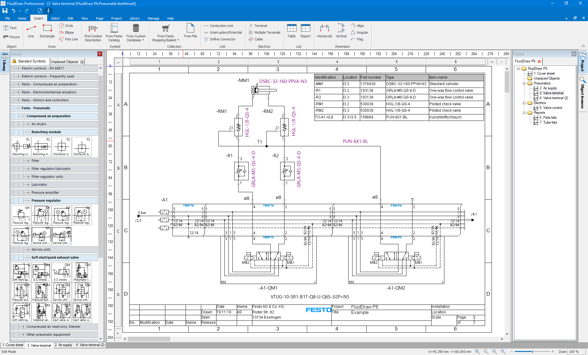
FluidDraw
Technical Resources - Pneumatic Circuit Diagram Keys Pneumatic circuit diagram symbols are shown here with an explanation as to what each diagram signifies.
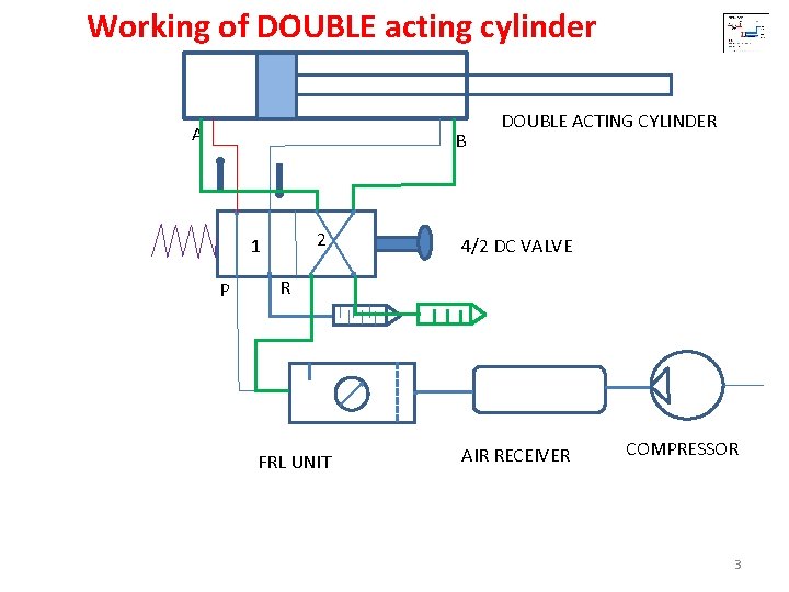
PNEUMATIC CIRCUITS 1 Working of SINGLE acting cylinder
PDF Basic Pneumatic Circuits - AutomationDirect The pneumatic circuit in Figure 5details a pneumatic two-hand safety control system for a press application. The circuit combines pneumatic buttons VLV01 and VLV02 configured as 3-way valves. These valves feed pilot air to a 4-way valve, VLV03.

Tutorial 5 - Electric and pneumatic circuits - User Manual
Pneumatic Symbols - SMC All the symbols you need to design your pneumatic circuit in .dxf format. Scan through and easily download the one you need.

PLC Pneumatic Circuit Control | PLC Programming Pneumatic System
PLC Pneumatic Circuit Control | PLC Programming Pneumatic ... Draw the pneumatic circuit, PLC wiring diagram and ladder diagram to implement this task. Solution PLC Wiring diagram and Ladder diagrams are shown in above Figure. when the push button PB1 is pressed state of the address I1 turns to 1 and thus there will be output 01. The output of 01 operates the solenoid Y1 and cylinder moves forward,

Pneumatic circuit diagram. | Download Scientific Diagram
4 Basic Pneumatic Circuits | Hydraulics & Pneumatics March 16, 2021 - Here are four simple circuits of pneumatic components that can be used alone or as building blocks in larger systems.
Basic pneumatic circuit
The schematic diagram of the electro-pneumatic circuit in the HSM. Download scientific diagram | The schematic diagram of the electro-pneumatic circuit in the HSM. from publication: Experimental analysis of electro-pneumatic optimization of hot stamping machine control systems with on-delay timer | The sustainability criterion in the manufacturing industries ...
Low Cost Automation Tutorial | Technical Tutorial - MISUMI
Pneumatics Practical Circuit Building - T4.ie The primary function of t4 is to prepare and support teachers to implement the revised syllabuses Architectural Technology, Design and Communication Graphics and Engineering Technology and the new subject Technology at Leaving Certificate level.
Pneumatic Systems
Graphic Representations of Electro-Pneumatic Circuits ... Pneumatic and Electric Circuit Diagrams. Circuit diagrams for electro-pneumatic control systems consist of a pneumatic plan that shows how the individual pneumatic components are connected to one another and interact and an electrical circuit diagram that illustrates how the electric components are combined.
Chapter 5 Pneumatic System Multi Actuator Circuit Prepared
Pneumatic circuits drawing | SMC United Kingdom Pneumatic circuits drawing Design your air circuit with PneuDraw PneuDraw allows you to draw pneumatic circuits quickly and easily. With the new online release, it is easier than never to draw your circuits. Beside pneumatic symbols the tool includes generic symbols as well as special symbols to design business processes and flow diagrams.

Bus Door pneumatic circuit
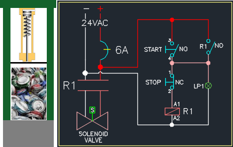
Pneumatic Can Crusher Circuit Diagram - HN mining ... Pneumatic Can Crusher Circuit Diagram. News Introduction:Pneumatic Aluminum Can Crusher and combine it with the idea that it can act as a recycle bin.Originally, we were going to do just a Can Crusher but we needed to add design features, the Can Crusher itself is mostly mechanical in its design.
Pneumatic Circuit Design - Airlane Pneumatics Limited
Untangling Pneumatic Circuit Symbols | Hydraulics & Pneumatics March 30, 2020 - Schematics for pneumatic circuits can be invaluable, but only if you know the symbology.
Explain pneumatic circuit for speed control of single acting ...
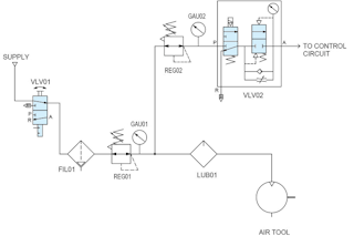
Basic Pneumatic Circuits - Tech Briefs August 11, 2021 - The air prep circuit diagram shown provides lubricated and non-lubricated air. Most pneumatic devices today do not need lubricated air but if lubrication is needed — such as with pneumatic air tools and motors — it should be adjusted for light oiling because too much oil can clog up the ...
Comparing an Electrical Circuit to a Pneumatic Circuit ...
Reading fluids circuit diagrams - hydraulic & pneumatic ... Pneumatic actuators. Fluid actuators are used to convert fluid energy into mechanical linear motion. For more information about reading hydraulic and pneumatic circuit diagrams, read the next article in this series which describes sample hydraulic circuits, or contact your Valmet representative.
Pneumatic Systems
Engineering Tools - PneuDraw SMC is a global company which counts on 1,500 R&D engineers to respond to our customers automation needs. We have the expertise and the passion to support you

Design aids for pneumatics
Reading fluids circuit diagrams - pneumatic circuit examples October 1, 2021 - This article describes two example pneumatic schematic diagrams: winder lowering cradle safety pins and winder belted threader operation.

PNEUMATIC CIRCUITS. - ppt download
PDF Pneumatic Control Schematics - Velvac Pneumatic Control Schematics • Applications shown in the document are: Lift axle circuits, suspension dump circuits and tailgate control circuits for single acting air cylinders. (Air to open spring to close) Single acting air cylinders require what is known as a 3 way valve function. Because Velvac valves are multi-purpose we can

Circuit diagrams, electro pneumatics - Diagrams - MPS® 2000 ...
FREE Fluid Power schematic design software - FluidPower.Pro A pneumatic circuit diagram can be easily created by using the database for pneumatic equipment drawing symbols. SMCDraw screenshot. Benefits: Some simple calculation can be made after system design (full stroke time, max velocity, flow, Dynamic characteristics simulation, etc.).
How to Design Efficient Pneumatic Systems | Clippard ...
How Works Pneumatic and Electrical Systems in a Process
PNEUMATIC CIRCUITS 1 Working of SINGLE acting cylinder

Solved 1. FIGURE 1 shows a pneumatic circuit diagram used ...
Solved Briefly explain the operating sequence of the | Chegg.com

Pneumatic circuit (Circuit no. 1) Control of Single acting cylinder.. #30kviews #viralvideo #circuit

Design of Sequential Electro-Pneumatic System | SpringerLink
How to Design Efficient Pneumatic Systems | Clippard ...

PLC Pneumatic Circuit Control – Instrumentation Tools ...

The schematic diagram of the electro-pneumatic circuit in the ...

Actuation Circuit with Custom Pneumatic Components - MATLAB ...
Pneumatic circuit diagrams – Learnchannel-TV.com

Pneumatic Circuit png images | PNGWing

Festo Mps Pneumatic Circuit Diagram s
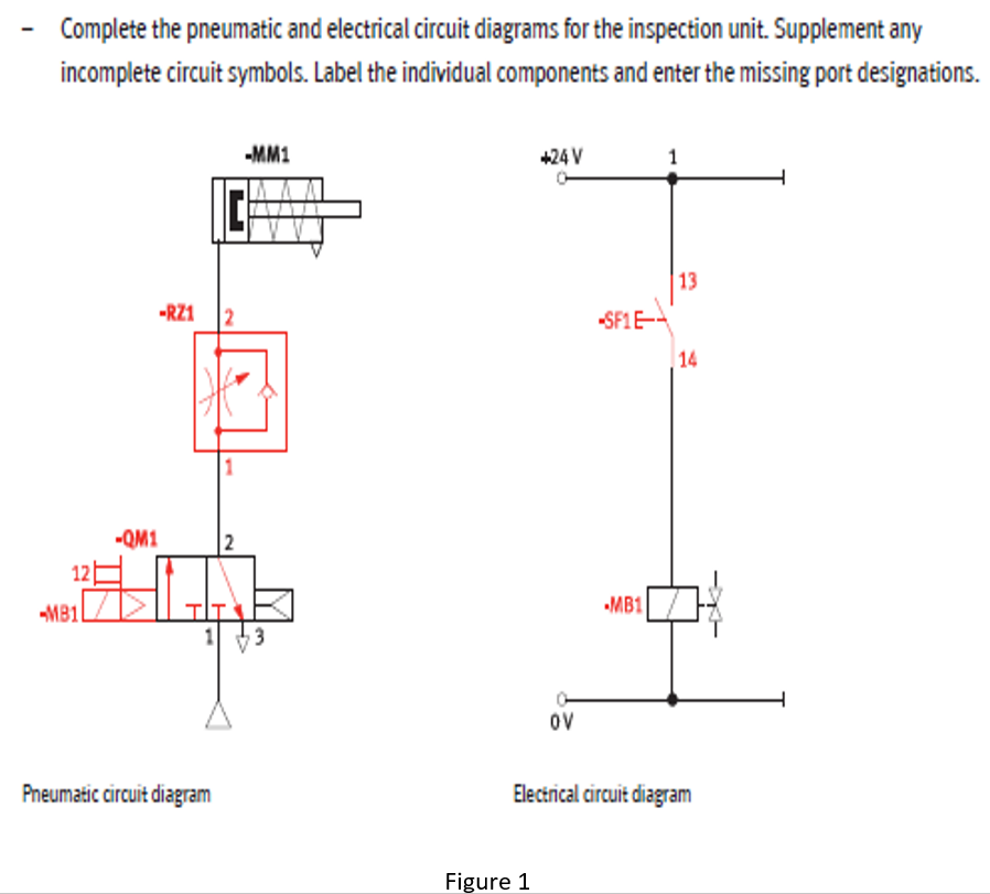
SOLVED:- Complete the pneumatic and electrical circuit ...
Reading fluids circuit diagrams - pneumatic circuit examples

Experimental analysis of electro-pneumatic optimization of ...


Comments
Post a Comment