40 cfl circuit diagram
› questions-and-answers › in-deeperAnswered: In deeper pipelines a branch prediction… | bartleby Transcribed Image Text: In deeper pipelines a branch prediction is very important because many more instructions are in flight and a wrong prediction would waste more time and power than that in a shallower pipeline. LX1686 Direct Drive CCFL Inverter Design ReferenceReference transistors and their required additional circuit component s. Direct Drive topology is a non-resonant, fixed frequency PWM regulation method for operating CCFLs. The LX1686 allows a wide choice of operating frequencies to match the lamp's most efficient operating point, and to minimize high frequency inter ference.
› wiring-devices › light-switches-andradiant® CFL/LED Dimmer, White | Dimmers | Light Switches and ... Oct 31, 2018 · Replaces any basic switch or dimmer with ease, in both single-pole and 3-way applications. Rated for use with the following dimmable bulb types: 450W LED,CFL, 700W Incandescent, or 120VAC, 60Hz; Low-profile paddle switch offers smoother On/Off control, while a separate, ergonomic slider allows you to adjust light levels with precision.

Cfl circuit diagram
circuitdigest.com › electronic-circuits › how-toHow to Make a Mini Tesla Coil 9v - Circuit Digest Oct 26, 2017 · Mini 9V Tesla Coil Circuit Diagram: The circuit diagram of Mini Tesla Coil Project given below is very simple. So let us understand how it works and learn how to build it. The main component in this mini tesla coil diagram is the secondary coil (golden colour), which is made by winding a magnetic wire (enameled) around a cylindrical object (any ... Compact Fluorescent Lamp - Working Principle, Construction ... In this topic, you study Compact Fluorescent Lamp - Working Principle, Construction & Circuit Diagram. Construction of Compact Fluorescent Lamp. Basically compact fluorescent lamp (Fig. 10.19) is a type of fluorescent lamp. There are two types of these lamps : ... Compact fluorescent lamps can fail prematurely if overheated. Related Topics. Mini Ups For Cfl Circuit Diagram - Wiring Diagram Line 45 W Single Cfl Inverter Kit For Domestic 12 V Rs 350 Pcs Gurukirpa Electronics Id 21845172588. Mini Ups For Cfl With Solar Battery Charger Inlyle It Systems. Mini Offline Ups Detailed Circuit Diagram Available. Cfl Lamps And Simple Inverter Delabs Electronic Circuits. 20 Watt Push Pull Cfl Inverter Circuit Circuits Diy.
Cfl circuit diagram. Compact Fluorescent Lamp Circuit (CFL) - Spactronics Fig 2 shows the diagram of CFL lamp circuit and the parts of CFL. The main three parts of CFL lamp is Base, circuit, and tube. We apply actual AC supply to the base. A CFL uses vacuum pipe which is same as tube light. Tube has two electrodes on both ends and they are treated with Barium. Cathode is having temperature of 900 0 C. CFL Circuit Repair All Fault With Circuit Diagram ... Hi guys hope you have enjoyed this Project feel free for any suggestions for future Project and ** "Remember To Stay Safe"**.If you are interested in my vide... CFL - How it Works, Circuit Explanation, Advantages ... Phase wise Circuit Explanation of CFL The working of a CFL can be divided into two broad phases: - Starting Phase Normal Phase Starting Phase The starter segment comprise of a Diac, C2, D1 and R6. The components D3, R3, D2 and R1 work as a protection circuit and the rest as normal operation circuit. Converting a Dead CFL into an LED Tubelight - Homemade ... To figure out the number of LEDs that would fit inside the output voltage of the above unit, we need to divide the measured voltage with 3.3V. Suppose the measured voltage was 120V, dividing this by 3.3 would give around 36 (numbers). Use the derived number of LEDs and connect all of them in series with a 5 Ohm, 1/4 watt series resistor. Done!
tahmidmc.blogspot.com › 2013 › 01Using the SG3525 PWM Controller - Explanation and ... - Blogger Jan 07, 2013 · Tahmid can i avoid connecting the ref to pin10..bcos i will like to use it with other control circuit for shut down...and plz can u mail me a well details feedback loop complete circuit diagram using 4n35 with sg3524 and sg3525.i will need it as soon as possible thanks. princequint@gmail.com CFL Ballast Wiring - Electrical 101 CFL Ballast with 2 Lamp Wiring Diagram Push-in connectors Slots for wire release CFL ballast side view CFL ballast front view Red wires connect to one side of the lamp, blue wires connect to the other. Yellow terminals are not used. Red wires connect to one side of one lamp, blue wires connect to one side of the other. cfl circuit diagram - Wiring Diagram and Schematics Typical Compact Flash Lamp Ballast Circuit 10 15 Fluorescent Scientific Diagram Power Factor Correction Of Compact Fluorescent And Tubular Led Lamps By Boost Converter With Hysteretic Control Phrases Tattoos For Girls Cfl Bulbs Circuit Diagram Application Notes And Circuits For Self Oscillating 25w Cfl Lamp Circuit › power-consumption-of-acCalculate the power consumption of AC & Electricity usage Power fluctuation diagram for Inverter and Non-inverter AC. Understanding Tonnage of AC. Air conditioning units are rated in tons. One ton is equal to 12,000 Btu per hour (3.517 kW). That is the amount of heat required (288,000 Btu) to melt one ton of ice in a 24-hour period. Therefore 288000, when divided by 24, gives 12000Btu, which is equal ...
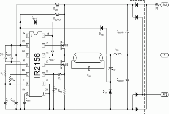
Compact Fluorescent Lamp (CFL) - Pavouk Inside is printed circuit board with components and wires from tube. Both plastic parts are clicked to himself and sometimes glued. Next you must leverage more to the opening lamp. For closing of lamp you can only click both plastic pieces to himself. Look at photo of opened lamp. Reviewing Fluorescent Light Electronic Circuits 42 Watt Compact Fluorescent Ballast - CFL-2 is an electronic ballast design for driving a 42 watt compact fluorescent lamp from a 120 or 230 volt AC line. circuit was designed usingIR2156 Ballast Driver IC. main features of circuit are programmable frequency, preheat time, over-current threshold and dead time. __ Cfl Driver Circuit Diagram - Wiring Diagram Line Cfl Driver Circuit Diagram. By Toshiko Liwanag | May 19, 2020. 0 Comment. Typical compact flash lamp ballast circuit 10 15 fluorescent scientific diagram cfl how it works explanation advantages disadvantages 12v inverter simple electronic 6v dc 20 watt florescent driver phrases tattoos for girls bulbs 4 65w with high efficiency help modifier ... 4 Pin Cfl Wiring Diagram - schematron.org 4 Pin Cfl Wiring Diagram 11.12.2018 6 Comments This device is designed for use with 13WW 4-pin compact fluorescent lamps Refer to lllustration 2 for switched and unswitched fixture wiring diagrams. for 4-pin Compact Fluorescent Lamps Dial the four digit extension of the Factor. converting 2-pin to 4-pin plug-in CFL? Dim./. Wiring. Diagram. Watts.
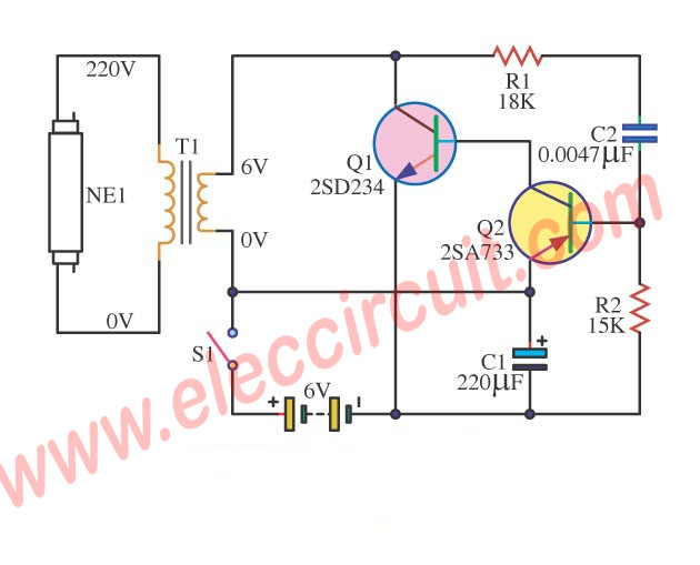
Fluorescent driver with 6V, 12V battery and blinking light ...
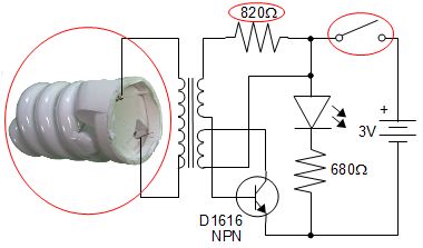
6v DC 20 watt Florescent Lamp Driver Circuit Basicaly this 6v DC 20 watt Florescent Lamp Driver Circuit is a self-oscillating on ~ 25-35 KHz. with R2 and C2 as frequency dependen parts. and one more image of the unit energizing a 15 watts cfl lamp portion only. Observe how brilliant the cfl light possess using just 6V battery cell gel !
14 Watt Compact Fluorescent Electronic Ballast
› small-amplifier-circuit5 Simple Preamplifier Circuits Explained - Homemade Circuit ... Sep 03, 2021 · The circuit diagram is for a preamplifier that can be employed with low impedance microphones, and should give an output signal of around 500mV. R.M.S. The prototype was found to work well with both 200 ohm and 600 ohm impedance dynamic microphones, but it should also work well with electret types which have a built-in FET buffer amplifier ...

How to Use Burnt Compact Florescent Light Circuit Module : 6 ...
Modifying a 240V Compact Fluorescent Lamp (CFL) for 12V ... The title of this page is a bit misleading since the actual fluorescent tube part of a CFL is neither 240V or 12V. It's the drive circuit that defines what voltage the lamp is going to run on, and whether it be mains or battery the tube will be driven the same. The reason for this project was that I had a 12V CFL that worked fine except it was ...
Fluorescent driver with 6V, 12V battery and blinking light ...
A simple LED lamp circuit from scrap. Uses 5 LED and takes ... Few components available in the CFL PCB also can be used. Procedure 1. Carefully remove the broken glasses 2. Open the assembly carefully 3. Remove electronics and discard 4. Assemble the circuit in dot matrix PC or on a 1mm laminate sheet. 5. Cut a round laminate sheet with (scissor) 6. Mark the position of the 6 round holes on the sheet 7.
CFL - How it Works, Circuit Explanation, Advantages ...
Cfl Light Circuit Diagram - Irish Connections Cfl Light Circuit Diagram. By Irish Bella | October 1, 2021. 0 Comment. Typical compact flash lamp ballast circuit 10 15 fluorescent scientific diagram cfl how it works explanation advantages disadvantages to repair bulb lesson learnt electronics and technology news 6v dc 20 watt florescent driver phrases tattoos for girls bulbs eetimes lamps ...
Compact Fluorescent Light (CFL) powered by electric fly swatter
Cfl Circuits Diagram : Output Of Compact Fluorescent Light ... Cfl bulb ballast circuit diagram. The schematic is shown below, but note that this is just the basic driver. So i thought what if i took the printed circuit board from the 12v cfl and. Circuit diagram for jeanna's light variation of joule thief circuit. Cfl schematics details for fcc id vgzgyt65u made by jiangxi midea guiya green lighting ...

Compact fluorescent lamp - Wikipedia
Cfl Driver Circuit Diagram - Irish Connections Cfl Driver Circuit Diagram. By Irish Bella | December 31, 2020. 0 Comment. Typical compact flash lamp ballast circuit 10 15 fluorescent scientific diagram cfl how it works explanation advantages disadvantages 12v inverter simple electronic 6v dc 20 watt florescent driver 4 65w with high efficiency phrases tattoos for girls bulbs to repair bulb ...

Smart Lighting Technologies Feature CFL Dimming Wireless ...
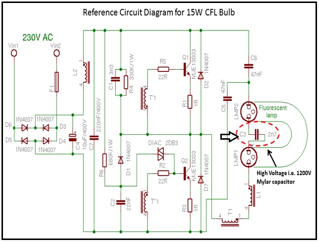
CFL Bulb Circuit Working Explanation - Electrothinks CFL bulb Ballast Circuit diagram The CFL bulbs present in the market have different wattage such as 5W, 9W, 11W, 15W, 20W, 25W, 30W, etc. So the internal ballast circuit is also different. Below is shown the circuit diagram of some CFL ballast boards. Working principle of CFL bulb ballast circuit Fluorescent Lamp Circuit Working Explanation.

Ballast for - Energy Saving Lamps
› street-light-circuitAutomatic Street Light Controller Circuit Using Relays and LDR Mar 09, 2012 · The circuit diagram present here is that of a street light that automatically switches ON when the night falls and turns OFF when the sun rises. In fact you can this circuit for implementing any type of automatic night light. The circuit uses a Light Dependent Resistor (LDR) to sense the light .When there is light the resistance of LDR will be ...
eec247 Information on compact fluorescent lighting
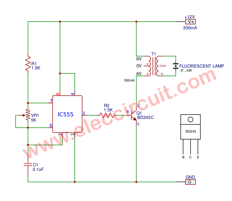
12v CFL Inverter Circuit, Simple CFL Inverter Circuit Diagram This CFL inverter circuit is operated using the 12v Lead-acid battery which is mostly used in all homes. In this inverter circuit, a 555 timer ic is used which is connected in astable multivibrator mode, so it produces the continuously on-off signal, this on-off signal called a pulsed signal. The preset is used to set the frequency at 50HZ.
Low Cost Simple CFL lamp – delabs Electronic Circuits
CFL circuit hack everyone should know - YouTube PLEASE SUBSCRIBE: friends, You would be surprised to know that the circuit inside the CFL lamp...

EETimes - How compact fluorescent lamps work-and how to dim them
Typical Compact Flash Lamp Ballast Circuit [10,15] Compact ... Exemplary block diagram of typical CFL ballast circuit has been presented in figure 1. Block 1 contains passive components (inductance L 1 , capacitance C 1 ) for harmonic filtering of CFL load...

Experimental characterization of compact fluorescent lamps ...
Mini Ups For Cfl Circuit Diagram - Wiring Diagram Line 45 W Single Cfl Inverter Kit For Domestic 12 V Rs 350 Pcs Gurukirpa Electronics Id 21845172588. Mini Ups For Cfl With Solar Battery Charger Inlyle It Systems. Mini Offline Ups Detailed Circuit Diagram Available. Cfl Lamps And Simple Inverter Delabs Electronic Circuits. 20 Watt Push Pull Cfl Inverter Circuit Circuits Diy.
Running a CFL light bulb on one AA battery - Pete's QBASIC Site
Compact Fluorescent Lamp - Working Principle, Construction ... In this topic, you study Compact Fluorescent Lamp - Working Principle, Construction & Circuit Diagram. Construction of Compact Fluorescent Lamp. Basically compact fluorescent lamp (Fig. 10.19) is a type of fluorescent lamp. There are two types of these lamps : ... Compact fluorescent lamps can fail prematurely if overheated. Related Topics.
Modified Energy Efficient Compact Fluorescent Lamp
circuitdigest.com › electronic-circuits › how-toHow to Make a Mini Tesla Coil 9v - Circuit Digest Oct 26, 2017 · Mini 9V Tesla Coil Circuit Diagram: The circuit diagram of Mini Tesla Coil Project given below is very simple. So let us understand how it works and learn how to build it. The main component in this mini tesla coil diagram is the secondary coil (golden colour), which is made by winding a magnetic wire (enameled) around a cylindrical object (any ...
Simplified Three Level Dimming Cfl Fluorescent Ballast Using ...

12V CFL Emergency Light Circuit Using 3525 IC | Mini Inverter ...

CFL Lamp Driver Circuit Diagram - Electronic Projects, Power ...

EETimes - How compact fluorescent lamps work-and how to dim them

UV lamps ballast problem - Project Guidance - Arduino Forum
LedDriveDC - CircuitLab

Use a CFL ballast to drive LEDs - EDN
Various Schematics and Diagrams
CFL Bulb Repair | Electronics Repair And Technology News
How does a CFL bulb circuit convert 220V AC to DC without a ...

4 Pin / G24 Socket CFL to LED Conversion for Canned Lights
Compact fluorescent lamp
Compact fluorescent lamp

cfl bulb component knowledge
Fluorescent driver with 6V, 12V battery and blinking light ...

Compact Fluorescent Lamps (CFL'S)—The Future of Lighting

Circuit diagram for fused cfl bulb... - We are an engineers ...

LED Emergency Light : 4 Steps - Instructables
4 Pin / G24 Socket CFL to LED Conversion for Canned Lights
Compact fluorescent lamp
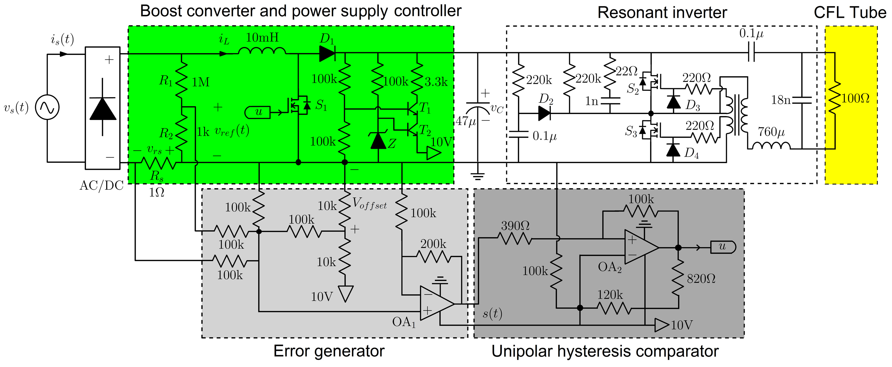
Power Factor Correction of Compact Fluorescent and Tubular ...

How to build 12Vdc to 220Vac 50W Converter - circuit diagram
How To Repair CFL Bulb -Lesson Learnt | Electronics Repair ...

50W Inverter 12VDC to 220VAC | Electronic Schematic Diagram
Compact fluorescent lamp


Comments
Post a Comment