42 proportioning valve diagram
Proportioning Valves 101 - FORDification.com The proportioning valve only lets a certain portion of the pressure through to the rear wheels so that the front wheels apply more braking force. If the proportioning valve were set to 70 percent and the brake pressure were 1,000 pounds per square inch (psi) for the front brakes, the rear brakes would get 700 psi. So how does it work? ˆˇ˘ ˝ ˛ ˜ ˛ˆ ˙ ˆ ˜ ˛ ˙ ˙ ˚ PVK - Proportioning Valve Diagram valve as shown in the diagram. #PVK - Proportioning Valve Diagram Rev. 1/13/2015 This diagram is the most common way to plumb a pro-portioning valve. In some cases, the right front line will be plugged off at the proportioning valve and the left front line will go to a “T” fitting. From the “T” fitting, the front lines then split off ...
PROPORTIONING VALVE DIAGRAM - Classic Perform PROPORTIONING VALVE DIAGRAM This diagram is the most common way to plumb a proportioning valve. In some cases, the right front line will be plugged off at the proportioning valve and the left front line will go to a "T" fitting. From the "T" fitting, the front lines then split off and go to the left and right wheels.

Proportioning valve diagram
Brake Proportioning Valve - Tilton Engineering inlet of the proportioning valve. The outlet of the proportioning valve is connected to the line leading to the caliper(s). Diagram 2 - Flow Diagram Diagram 4 - Overall Dimensions (Handle shown in Position 1, referring to Chart 1) 3.98" (102mm).50" (12.8mm) 3.00" (122mm) 1.00" (25.4mm) OUT IN Diagram 3 - Typical Applications Diagram 1 ... Brake Proportioning Valve Diagram Recipes - TfRecipes PROPORTIONING VALVE DIAGRAM. This diagram is the most common way to plumb a proportioning valve. In some cases, the right front line will be plugged off at ... INSTRUCTION -31351, 9103152, 910-31364, 910-31366 S ... Proportioning Valve Plumbing The most common proportioning valve plumbing is shown below. An alternative plumbing method is to plug off the top front line and have the bottom front line go to a “T” fitting. From the “T” fitting, the front lines are then split off to the left and right calipers. Proportioning Valve Kit Build Sheet 1.
Proportioning valve diagram. 66-77 Early Ford Bronco Disc Brake Proportioning Valve Diagram You can download this Bronco Proportioning Valve Diagram as a PDF here: 66-77 Early Ford Bronco Disc Brake Proportioning Valve Early Bronco Proportioning Valve Diagram Recent Posts 2021 TOMS OFFROAD $12,000 Christmas Kickback! 2021 TOMS OFFROAD 5 Days of Free Promotion Steering Wheel Horn Grounding Instructions for 74-77 Ford Broncos Adjustable Proportioning Valve Block Installation 22/06/2021 · The Speedway Motors adjustable proportioning valve block, brake distribution system P/N 910-31367-BLK has it covered for you. I chose the black one for my 1976 Chevrolet Laguna S-3 because the car is going to have a blackout appearance, but the valve kit is available in a chrome finish as well under Speedway Motors P/N 910-31367-CHR. Proportioning Valve Rebuild - Classic Car Restoration Club The proportioning valve determines the percentages of brake fluid directed to the front and rear brakes to ensure safe braking. Bob Wilson owner of RJ Restorations explains how the proportioning valve functions and demonstrates the process of rebuilding one. You Might Also Enjoy. What is the electrical connection on the proportioning ... The one by the proportioning valve as well as the one by the emergency brake operate the brake warning light on the dash. For example, when the emergency brake is set the switch moves to ground which completes the circuit and the warning light illuminates. Releasing the emergency brake opens the circuit on the ground side which extinguishes the ...
Brake Proportioning Valves - Brakes-shop.com Height-Sensing Proportioning Valves Some vehicle's proportioning valves go one step farther, as the kneepoint on the graph can vary with the amount of weight on the rear axle. Effectively, as the rear axle weight increases, a linkage between the axle and the body is compressed. Brake Line Kit Plumbing Diagram - Classic Perform The valve should be installed on the brake side of the proportioning valve as shown in the diagram. When using a dual master cylinder with Disc front, Drum rear combinations you won't need to remove the residual check valve as it only applies pressure to the rear brake line. Stock proportioning valve diagram | Ford Mustang Forums Stock proportioning valve diagram. Jump to Latest Follow 1 - 9 of 9 Posts. 9. 93TripleBlack · Registered. Joined Apr 12, 2014 · 129 Posts . Discussion Starter · #1 · Mar 24, 2015. Only show this user ... Residual vs Proportioning Valves and What Your Brake ... 26/01/2021 · Brake proportioning valve adjustment may seem like a complicated process, but it is quite simple. For all street driven vehicles, the valve will be placed in the rear brake line to reduce the amount of fluid pressure supplied to the rear brakes. The amount of pressure reduction to the rear is adjustable by turning the knob on the proportioning ...
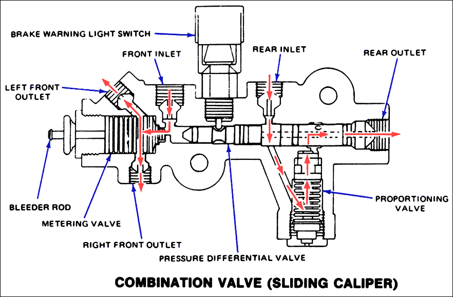
Proportioning valve diagram - Fixya Cars without ABS have a device called a proportioning valve. This valve is designed to supply 70% of the stopping power to the front brakes and the remaining 30% to the rear. Without this valve, the rear brakes would constantly be locking up. On cars with ABS, that valve is built into the ABS unit. Brake System Diagram - Street Rod - Speedway Motors This diagram shows a typical street rod brake system. A 2 PSI residual pressure valve (RPV) is needed in the disc brake circuit, and a 10 PSI RPV is required in the drum brake circuit as well as an adjustable proportioning valve (APV). This diagram illustrates the 2 most common types of fittings used in street rod brake systems. Brake Proportioning Valve - INSTALLATION INSTRUCTIONS Select the routing of the hydraulic lines carefully and avoid any heat sources such as the exhaust pipes and manifolds. 7. Refer to Diagram 2 and connect the ... POLARIS 2007 SPORTSMAN 500 EF SERVICE MANUAL Pdf … Valve Guide Installed Height Place 46 cutter on the pilot and make a light cut. Valve Guide Height: 10. Page 83 ENGINE 13. Remove valve and check where the Prussian Blue™ NOTE: When using an interference angle, the seat contact point on the valve will be very narrow, and is a indicates seat contact on the valve face.
Custom front brake line routing | For A Bodies Only Mopar Forum
Proportioning Valves - Herm The Overdrive Guy We offer proportioning valves in our kits, as well as sell them separately for all your needs. USPS Priority shipping Flat $8 on these listed proportioning valves PV-2 (disc front, drum rear) PV-2 diagram pdf $55 PV-4 (disc front, disc rear) PV-4 diagram pdf $55 PVC-B (adjustable) PVC-B diagram pdf $75
Proportion valve - Dodge Ram, Ramcharger, Cummins, Jeep, Durango, Power Wagon, Trailduster, all ...
horst-dieter-bernecker.de Fuse box symbols meaning Dec 20, 2021 · Besko loader valve diagram Daedong 3 cyl diesel Make Model Search Dec 12, 2021 · Besko loader valve diagram Bobcat hydraulic oil overheating Sep 16, 2015 · Looking at a used Kioti Ok, I have an opportunity to get a Kioti, and the problem it has is a bad wheel bearing. ,000 Ex GST.
Wilwood Combination Proportioning Valve
JEGS High Performance Parts | Aftermarket Auto Parts ... Auto Trans Valve Body Separator Plate (13) Automatic Transmission Shift Kit (147) Bellhousing (15) Bellhousing Dowel Pin (7) Body Bolt (5) Body Molding (6) Bolt (6) ... JEGS Wiring Diagram for 1958-1960 Ford F-Series Truck, 11 in x 17 in., Laminated. JEGS …

| Repair Guides | Brake Operating System | Proportioning Valve | AutoZone.com
Product Detail - Ansul Bladder Tanks are a component of a balanced pressure proportioning system that includes a pressure-rated tank with an internal elastomeric bladder for foam concentrate storage. Upon system actuation, incoming water applies pressure to the concentrate in the bladder, which supplies pressurized concentrate to the proportioning device.

67 proportioning valve query - Vintage Mustang Forums
Wilwood Brake Proportioning Valve Diagram | vincegray2014 Brake Proportioning Valve Wire Diagram. Chevy Proportioning Valve Diagram. 48re Valve Body Diagram48re Valve Body Diagram. 1.8t N75 Valve Diagram. Vw N75 Valve Diagram. N75 Valve Diagram 1.8 T. N75 Valve Diagram 1.9 Tdi. Schrader Valve Diagram. Rainbird Dv Valve Diagram.
converting to disc... proportioning valve? manual brakes? - Chevelle Tech
PV2/PV4 Proportioning Valve KIT Installation Instructions PV2/PV4 Proportioning Valve KIT Installation Instructions (left Side Kit used for example, but instructions apply to all kits) Included in this Kit: 1 Proportioning Valve 2 Pre-bent lines 1 Brake light wiring harness 1 Mounting bracket 2 5/16-18 bolts 2 washers-flat 2 washers-split locking Proper operation of your brakes is

Wilwood Proportioning Valve – Battle Garage Racing Service
Adjustable Proportioning Valve Diagram Recipes - TfRecipes This diagram is the most common way to plumb a proportioning valve. In some cases, the right front line will be plugged off at the proportioning valve and ...

1966 Mustang master cylinder HELP!! - Ford Mustang Forum
How to Get a Proportioning Valve Unstuck | It Still Runs The brake proportioning valve is a metering device that equalizes the pressure between the front and rear brakes. The valve stops the flow, or pressure of brake fluid to the rear drum brakes during every heavy braking or emergency stops; otherwise, the rear brakes lock up and skid, receiving too much pressure from the master cylinder.


Comments
Post a Comment