39 boiler system diagram
The boiler circulating system - Gray Furnaceman Furnace ... The above diagram is a simplified boiler gravity circulating system. As the water arrives at the bottom of the boiler, the burning fuel warms the water. The warm water naturally rises through the angled pipes to the terminal unit which transfers the heat from the water to the heated space. Steam Boiler Diagram With Parts for Dummy's Steam Boiler Diagram The diagram above is showing the boiler parts which are mandatory for the design and operation of steam boiler. Hence each boiler part plays important role and everyone interested to know more about boilers can learn from this page in the last section. Lets first see some basic information about boilers.
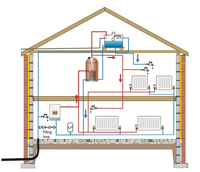
Hot Water Heating Boiler Operation Details - 39 steps in ... What follows is a detailed, step by step description of how a heating boiler works. We name each heating system component and what it does, in the order that heating system components operate during the heating cycle. Items shown in [brackets] are ones which may not be present on some heating systems.
Boiler system diagram
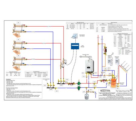
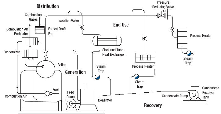
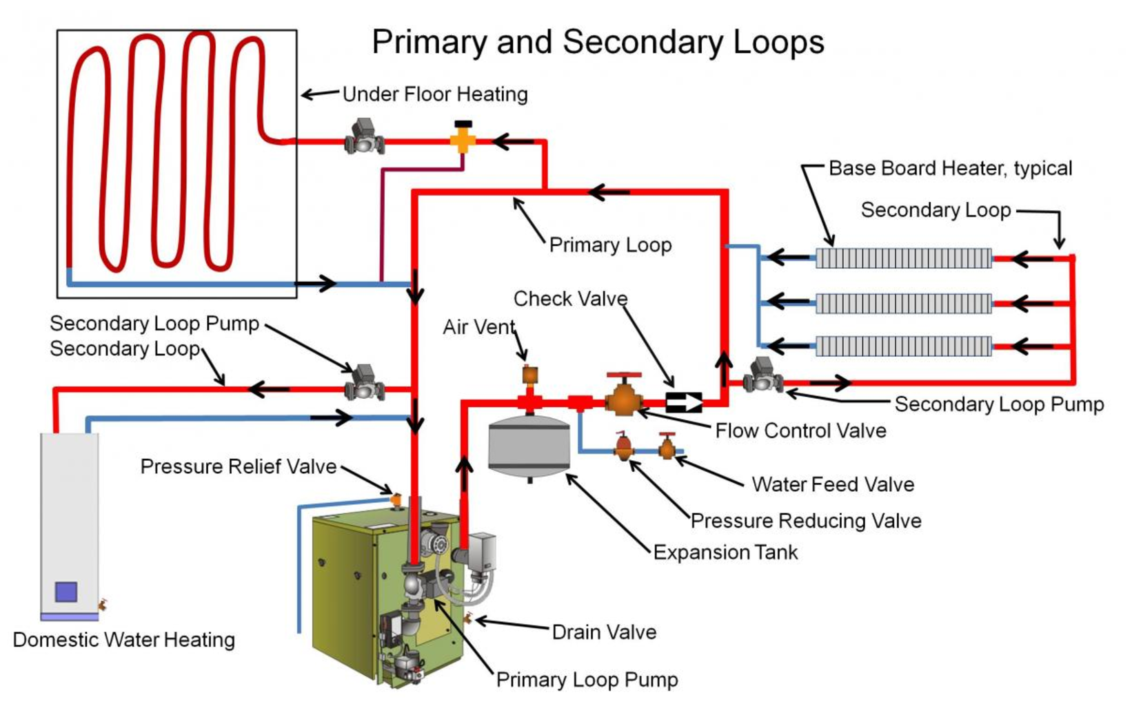
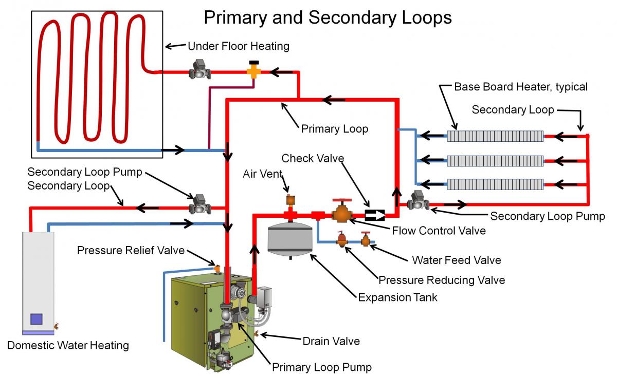
PDF BASIC HYDRONIC SYSTEM DESIGN - ctashrae.org BASIC HYDRONIC SYSTEM DESIGN Generation Equipment Boilers, Chillers, Cooling Towers, WWHPs, etc. Terminal Units Fan Coils, Chilled Beams, Finned Tube, Radiant, etc. Decoupler Primary Pumps Closely Spaced Tees P-1 & P-2 Distribution Piping Air / Dirt Separator Expansion Tank Secondary Pumps P-B-1 & P-B-2. 2 REFERRING TO PUMPS HEATING P-CH-1 PDF System Diagrams - Central Boiler System Diagrams H C M R Thermostatic Valve (optional) NOTE Outdoor furnace water temperature setpoint should be set at 185˚F minimum. NOTE A pump must be installed in the hot supply line between the outdoor furnace and thermostatic valve. Existing Boiler Hot Supply 1" Central PEX® This horizontal assembly must not exceed a height of 4 inches ... PDF Hot Water Boilers - Keystoker of the heating system. Install a 1/2 " ball valve in pipe going to expansion tank with direction marker on valve pointing toward the expansion tank. (See Diagram Pg 5). Install immersion well for low water cut off, in ¾" fitting on side of boiler above fire door in lower hole closet to unit end of boiler (See Diagram Pg 5).
Boiler system diagram. Block Diagram of a Boiler System | Download Scientific Diagram Boiler system consists of five main subsystems namely furnace, riser, drum, reheater and superheater [7]. Based on the typical drum-type boiler, the feedwater is supplied to the drum where the... Heating diagrams for boilers, buffer tanks and solar ... All system components from Solarbayer, including a wood gasifying boiler, stratification buffer tanks, solar DHW tank and a thermal solar system with flat plate collectors. Heating diagrams A collection of hydraulic drawings of established installation Guide To Central Heating Systems | gravity fed system Combination Gas Boiler System. Combination Boiler System Diagram. Often referred to as a 'combi boiler' this type of installation heats hot water as you ... PDF Commercial Boilers & Water Heaters | Patterson-Kelley Commercial Boilers & Water Heaters | Patterson-Kelley
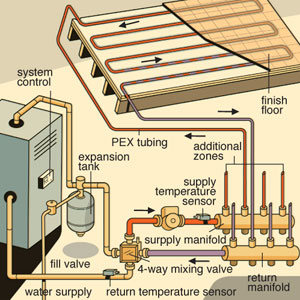
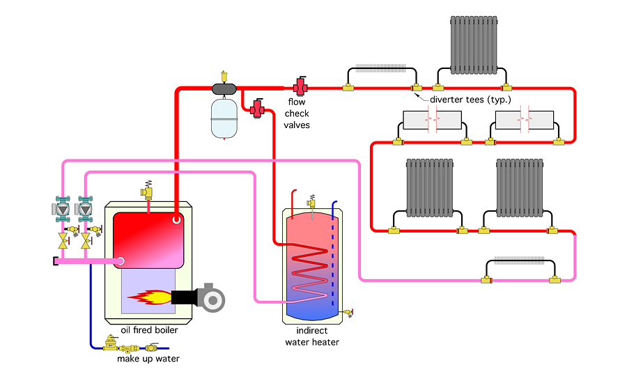
Boiler Piping Diagram For Radiant Heat Wiring diagrams for all controls, thermostats and temperature sensing devices. In a radiant heating application, a properly sized pump on the Primary Loop triggers the Unless, as stated above, a specific boiler manufacturer requires Primary/Secondary The schematic below illustrates the piping configuration when. PDF I. PIPING DIAGRAMS - Water and Space Heating 13. Wire the tank or system/pipe sensor connected to the DHW sensor terminals on the follower boiler addressed as #1. 14. The system/pipe sensor must be placed on common piping to the tank, as close to the tank as possible. 15. The system/pipe sensor is wired to the system sensor terminals on the master boiler. Boiler Feed Water System Diagram and Explanation - What is ... These four components comprises of a cyclic process that starts from the formation of high pressure, highly compressed steam by the boiler. The high temperature steam goes to the turbine, where it operates the turbine and comes out in the form of exhausted low energy steam. Residential Boiler System Diagram Recipes - TfRecipes This wiring diagram shows 120 V coming from L1 of a circuit breaker, through a switch, powering a boiler control and returning through L2, back to the neutral ...
Parts of Boiler and Their Function in the Boilers | Linquip The boiler definition Boilers are systems used to heat a fluid (usually water) in a closed vessel. It can be boiled, heated, or vaporized. You can then use the outcome for various purposes or heating applications such as cooking, water heating, sanitation, central heating, boiler-based power generation, etc. PDF 5 System diagrams boiler) (System diagram = 12, VR 70 configuration = 5) 10 System diagram 12 -5 Complete hybrid system with heat exchanger, auxiliary heater does not require pump of heat pump (DHW by heat pump and boiler) (System diagram = 13, VR 70 configuration = 1) 11 System diagram 13 -5 12 What is a System Boiler? Pros, Cons & Costs | Boiler Guide On average, the installation of a new system boiler will cost between £800 - £1,500. In the table below, we reveal the potential cost of the best system boilers including the installation. Depending on the complexity of the installation, a system boiler can take anywhere between 1 and 3 days. Boiler Piping Diagram For Radiant Heat - schematron.org Wiring Diagram Roth Shunt Systems Boiler with Heat Exchanger and Variable Speed Injection Pump Using the Chart. The photo above is our "Radiant Ready A/T" single zone Closed System for use with an on-demand water heater.
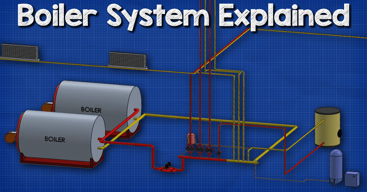
Boiler System Explained (LTHW) - The Engineering Mindset
PDF ENGINEERING MANUAL Industrial Boilers Hot water boilers are normally used in room and process heating. This kind of system is suitable for discharge temperatures up to 140°C. The advantage of hot water over steam is that energy loss is lower than with steam boilers. 2. Thermal oil boiler In hot oil boilers is used oil in stead of steam or water. The advantage with oil is that the
Piping Diagram
Schematic of typical combi boiler heating and hot water ... Combination boilers offer a compact, low cost and low disruption solution for conventional central heating systems which, in the case of boiler replacement, ...
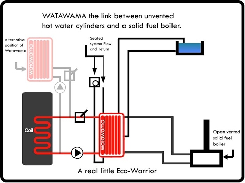
Sealed Heating System Diagram Design
How Steam Boiler System Works? - Linquip If you want to understand the steam boiler system diagram, you need to know what a steam boiler is. The steam boiler definition is that it's a type of heat exchanging system that heats the water to create the steam for the desired purposes.

A new method for heating domestic water in pellet-fired ...
PDF Design of Boilers Piping - National Board of Boiler and ... Design of Boilers and Power Piping ASME Code Section I (Power Boilers) can be thought of as a "System Code Section" and includes by reference, ASME B31.1 (Power Piping) with specific rules for Boiler External Piping. Section I Scope •Boilers with an MAWP greater than 15 psi steam or 160

Steam Boiler Diagram With Parts for Dummy's
Hydronic Heating Boilers - Water Heaters Hydronic Heating Boilers Description Series Piping Diagram PDF Piping Diagram DWG Genesis® One Boiler Primary, Secondary Hydronic Heating System GB 300 2500 AOSHG61080 AOSHG61080 Genesis® Two Boilers Primary, Secondary Hydronic Heating System GB 300 2500 AOSHG61081 AOSHG61081 Genesis® Three Boilers
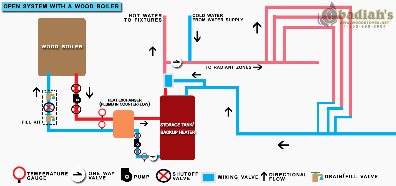
Open or Closed System Boiler? - Obadiah's Wood Boilers
What Is A System Boiler? The Complete Guide - HomeSage 5 Jun 2020 — The boiler has the major heating and hot water system components built-in. ... This system boiler diagram will visually help: System Boiler ...
Boilers - Chipkin Automation Systems
Central heating diagram - Mike the Boilerman This diagram illustrates how simple the heating system connected to a combi boiler is. No external pump, no tanks, no external expansion vessel, no motorised valves and in many cases item 6 is not needed either. (An automatic bypass valve is fitted inside most combi boilers by the manufacturer these days.)
Boiler Introduction | CleanBoiler.org
PDF Typical Piping for Conventional Single Boiler Installation ... System Notes: • The System Pump must be sized to maintain the minimum recommended flow rate through the boiler. The pump must operate continuous or cycle with the boiler. • The by-pass is required for systems designed to operate at flow rate higher than the maximum recom-mended flow rate of the boiler.
Working Principle | Boilers Guide
PDF UNDERSTANDING CENTRAL HEATING SYSTEMS Dec13 Open vented system layout This system is laid out as in the picture, with the main heating flow from the boiler being pumped into the motorised valve which chooses where the water goes depending on what the programmer tells it to do. Sealed central heating system layout

Hydronic heating system | It's all Important 4 notes - Lambda ...
Boiler Wiring Diagram Diagrams Schematics Stunning ... Emergency installation, drop header, large residential steam boiler pics in no particular order. Here are some pics of a recent job. We've got to go back and ...

BOILERS | Energy-Models.com
Conventional, Combi and System boiler systems explained The central heating portion of a combi is on a pressurised closed loop system, heated by the boiler as required. For domestic hot water the mains supply is fed direct to the boiler. This means no hot tank to refill, and a constant supply of hot water at mains pressure. The downside is that if more than one tap is open, the water pressure can fall.
Pressurized Storage Solution for Biomass Boilers | Hearth.com ...
diagram of boiler system comY-Plan boiler systems are designed to control the flow of hot water. ... comKnowing how to read a cooling system diagram is important if you want to able ...
UNDERSTANDING CENTRAL HEATING SYSTEMS
How combi boilers work diagram - Boiler Work How combi boiler works diagram. Combi boilers are designed to be manufactured with two independent heat exchangers, one of which carries a pipe to the radiators while the other one carries a pipe to the hot water supply. As soon as you turn the hot tap on, your boiler fires up to heat water and a valve gets opened to let the water flow through ...
Modern Central Heating
Diagram of a combi boiler setup - Pinterest Guide To Central Heating Systems - combi boiler system | gravity fed system | high pressure system | central heating diagram.

Types of heating systems Diagram | Quizlet
PDF FULL-COLOR TRAINING GUIDE SERIES - PB Heat: Peerless® Boilers SIZING THE BOILER 1. The boiler output must be large enough to satisfy all connected radiators. 2. Size the boiler by doing a radiator count, totaling all of the connected Square Feet. 3. Select a boiler with a Steam Net Load Rating (in square feed of EDR) greater than the total connected radiation. 4.

Boiler diagram Images, Stock Photos & Vectors | Shutterstock
diagram of boiler system - asia-boilers.com Although designs vary, a boiler has four main parts: the burner, the combustion chamber, the heat The Digestive System Diagram, Organs, Function, and More Just how do we digest our food? WebMD explains the digestive system, from the top to bottom. "Just a spoonful of sugar " goes the song. But what happens to that sugar once you swallow it?
The ultimate guide to being efficient with heating and hot ...
Boiler Manuals and Wiring Diagrams for Columbia Boiler Co ... Most of the wiring diagrams are for natural gas powered steam boilers. Wiring diagrams for oil burning and water boilers are noted. CT 6, 10, 15 and 25 boiler wiring diagram CT 6 and 25 boiler wiring diagram CT 35 and 50 boiler wiring diagram HRT 20 and 30 boiler wiring diagram Keystone series boiler wiring diagram

Energy Management
PDF Hot Water Boilers - Keystoker of the heating system. Install a 1/2 " ball valve in pipe going to expansion tank with direction marker on valve pointing toward the expansion tank. (See Diagram Pg 5). Install immersion well for low water cut off, in ¾" fitting on side of boiler above fire door in lower hole closet to unit end of boiler (See Diagram Pg 5).
Boiler System: HVAC Series Part V
PDF System Diagrams - Central Boiler System Diagrams H C M R Thermostatic Valve (optional) NOTE Outdoor furnace water temperature setpoint should be set at 185˚F minimum. NOTE A pump must be installed in the hot supply line between the outdoor furnace and thermostatic valve. Existing Boiler Hot Supply 1" Central PEX® This horizontal assembly must not exceed a height of 4 inches ...

What Is Boiler? | Types of Boiler | Steam Boiler | How Boiler ...
PDF BASIC HYDRONIC SYSTEM DESIGN - ctashrae.org BASIC HYDRONIC SYSTEM DESIGN Generation Equipment Boilers, Chillers, Cooling Towers, WWHPs, etc. Terminal Units Fan Coils, Chilled Beams, Finned Tube, Radiant, etc. Decoupler Primary Pumps Closely Spaced Tees P-1 & P-2 Distribution Piping Air / Dirt Separator Expansion Tank Secondary Pumps P-B-1 & P-B-2. 2 REFERRING TO PUMPS HEATING P-CH-1

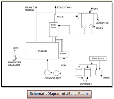
SCHEMATIC DIAGRAM OF THE BOILER WITH ECONOMIZER SYSTEM ...
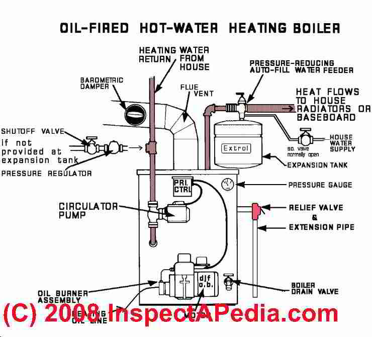
Hot Water Heating Boiler Operation Details - 39 steps in ...
Boiler Claims 101: The Basics of a Residential Boiler - HVAC ...
Open or Closed System Boiler? - Obadiah's Wood Boilers
Our Systems approach to installing Guntamatic boilers | Treco

Schematic of typical combi boiler heating and hot water ...

Boiler and System Types.

Piping Layouts for Hydronic Heat | JLC Online

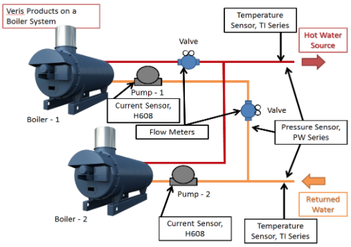
Basic Components on a Boiler System Diagram | Quizlet

hot water boiler system diagram Archives - ROMA Heating ...

The Steam Boiler System | Download Scientific Diagram
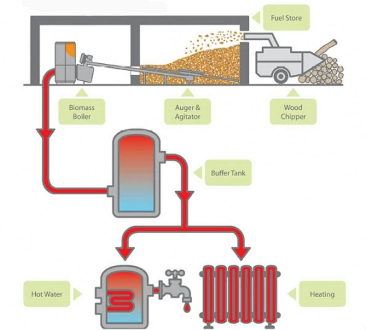
Retrofitting with a pellet boiler | 2016-02-02 | Plumbing and ...

Hydronics Zone: Combining a Water-to-water Heat Pump with a ...
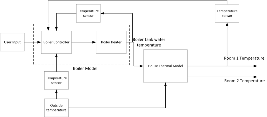
step by step design of a home gas boiler system (In | Chegg.com

Central heating diagram
Inspecting Gas-Fired Boilers - InterNACHI®
Design of Hot Water Heating Systems
Gas-Fired Boilers | Building America Solution Center

The Ultimate Guide to System Boilers | 2022


Comments
Post a Comment